Building a bigger Easton & Anderson Grasshopper

Home Model Engine Machinist Forum

Help Support Home Model Engine Machinist Forum:

This site may earn a commission from merchant affiliate links, including eBay, Amazon, and others.
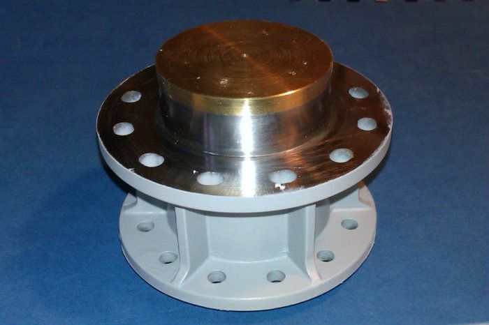
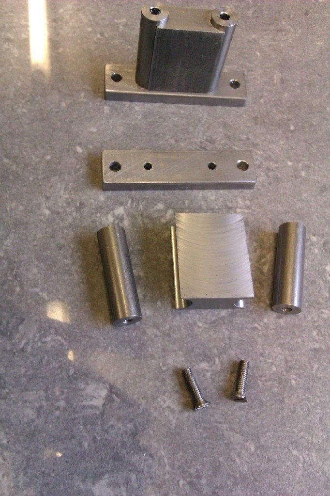
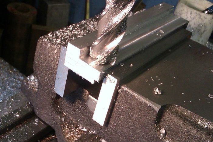
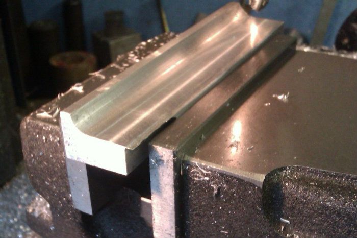
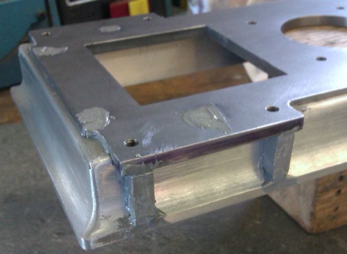
For the base of the engine I had intended to use a length of 125x65x15 PFC (parallel flange channel) that I had conviently over ordered on an order for some other work related structural steel. Having now got pictures of the actual engine I had to rethink my methods therefore I will make the top of the base from 5mm steel plate and the sides from 1 1/2" x 5/8" alloy.

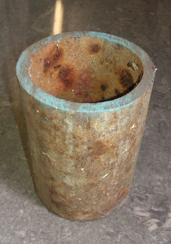
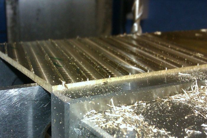
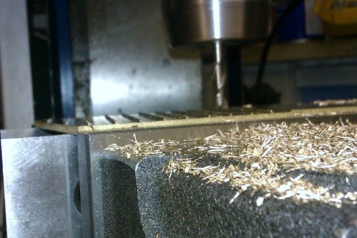
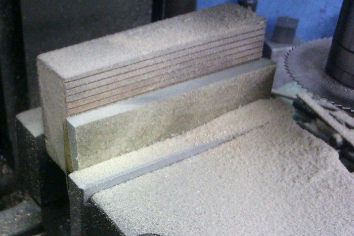
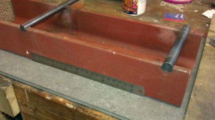
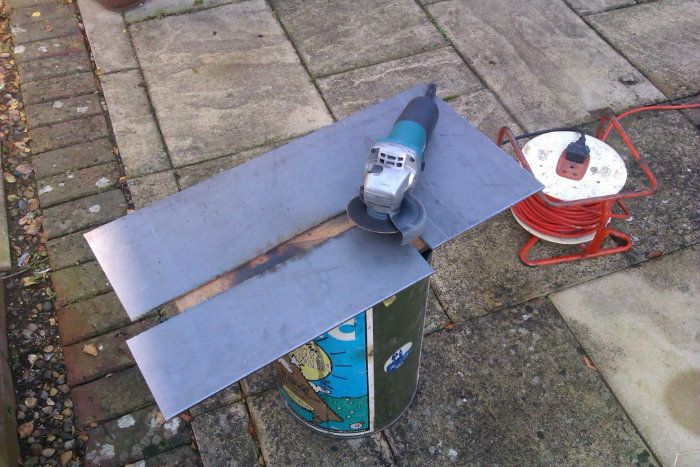
You know when you are building bigger engines because you can't cut right through the part with a hacksaw ::) , so the angle grinder with a thin cutting disc was used to complete the cuts and give me a piece approx 5" x17"

IMAG0922.jpg


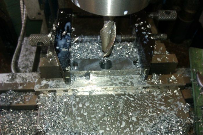
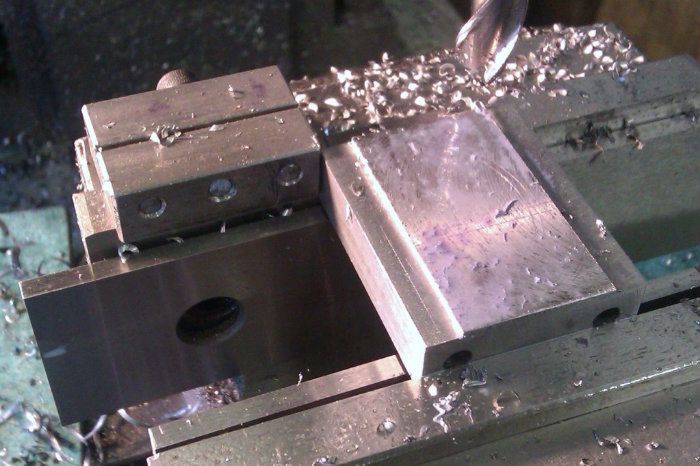
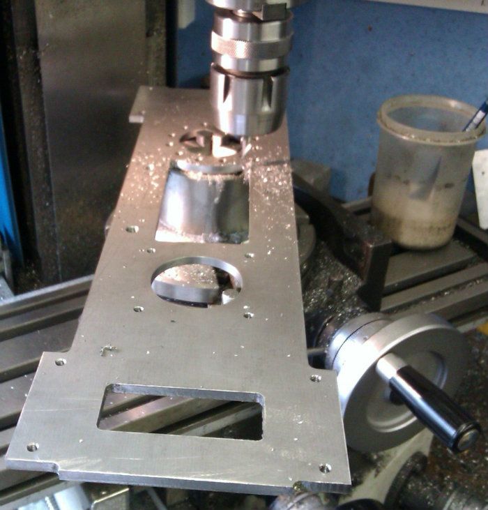
After some very basic layout using a pencil and marker the sheet was fixed to the mill table on some MDF packing.

IMAG0924.jpg


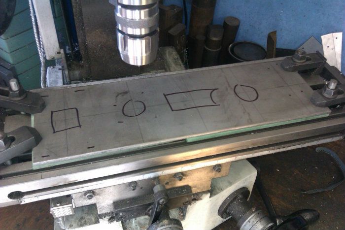
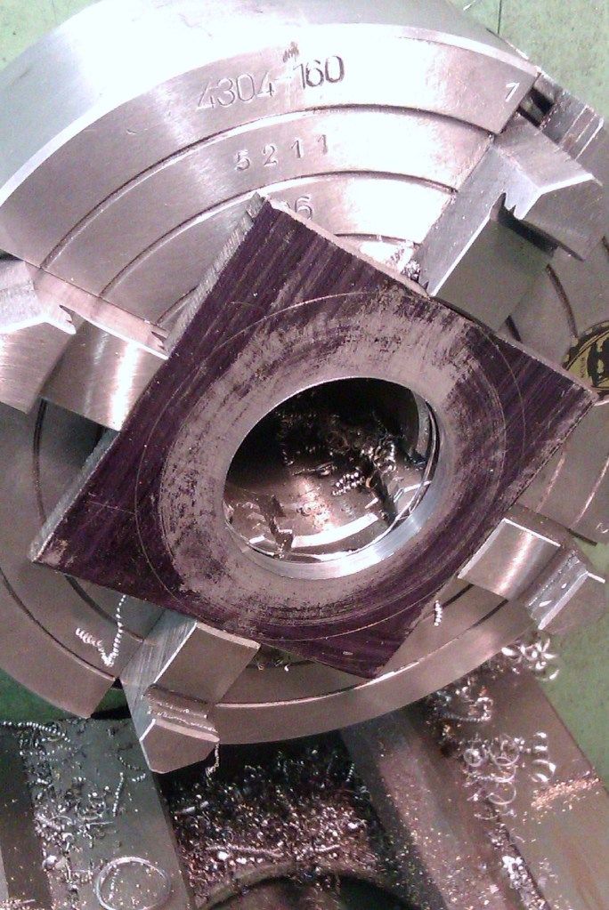
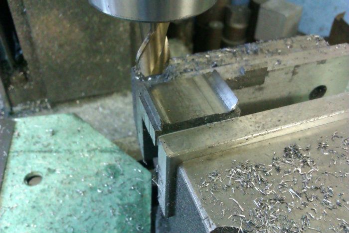
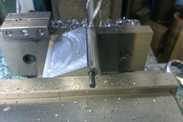
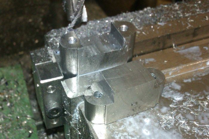
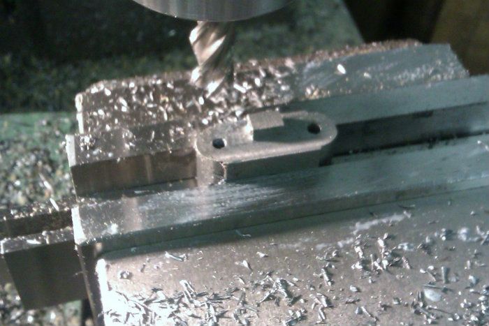
The first job was to add another hold down in the middle of some waste followed by cutting the two holes for the pump and cylinder base using a boring head and their associated fixing holes.

IMAG0925.jpg


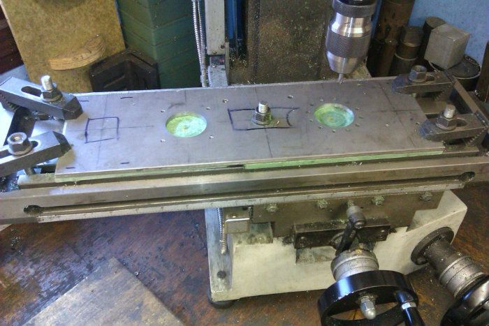
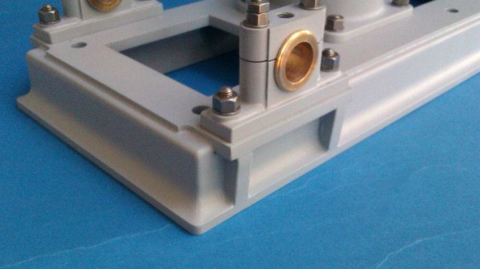
As work progressed I had to reset the plate as its length was just over the 360mm travel of the X3s table. Having studied the old photos again tonight I need to make this rectangular hole larger but its easy enough to reset on the mill.

IMAG0938.jpg


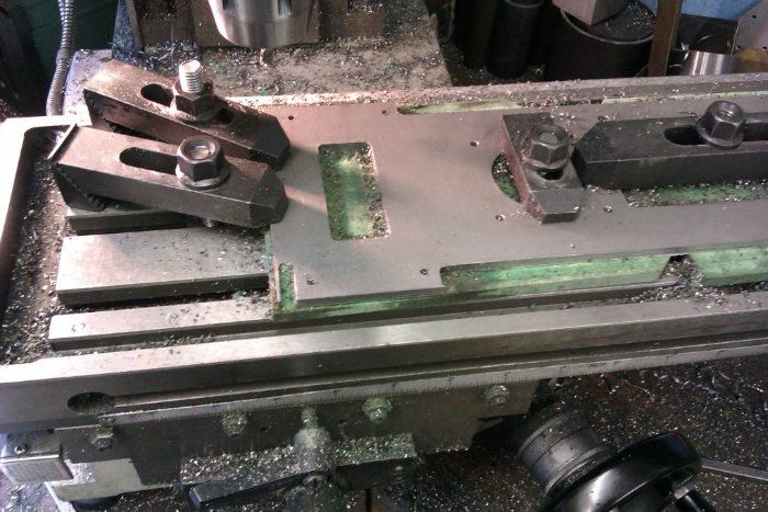
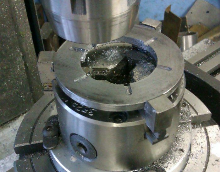
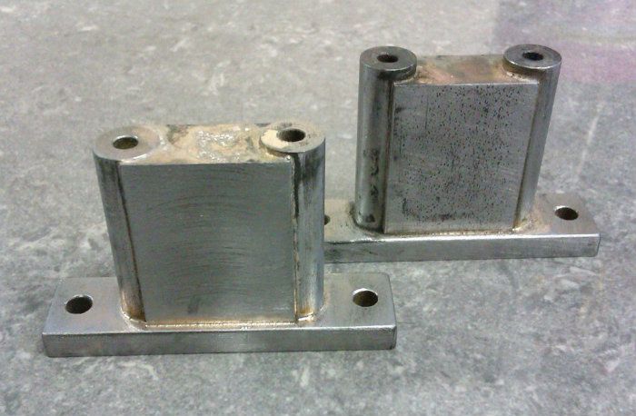
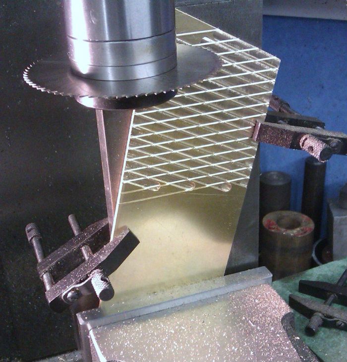
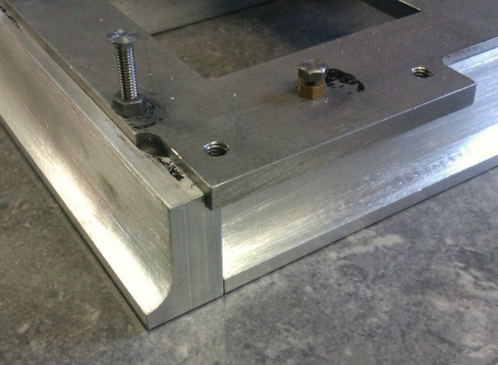
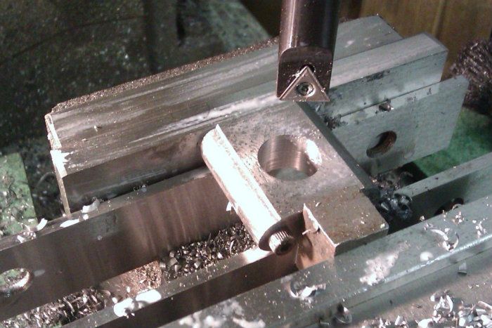
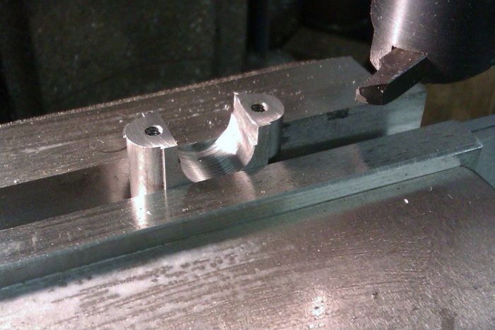
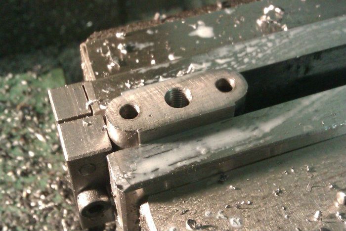
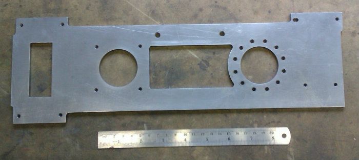
The final bit of profiling was done on the rotary table as the crank hole needs to have a rounded end where it meets the cylinder base.

IMAG0939.jpg


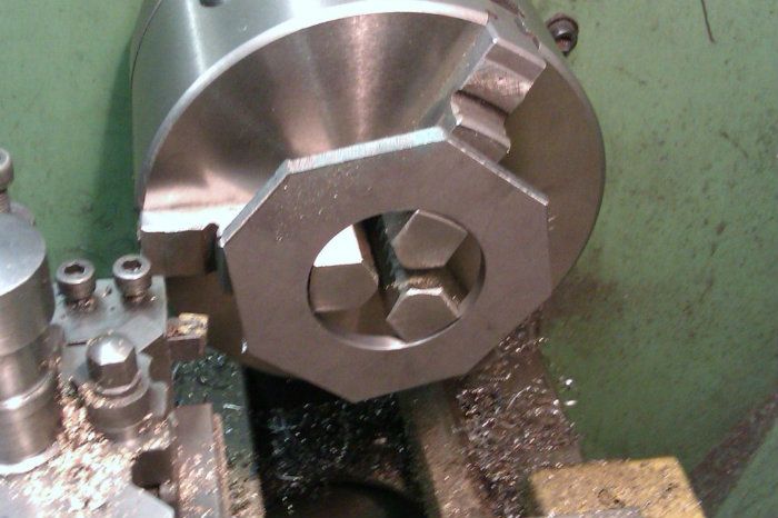
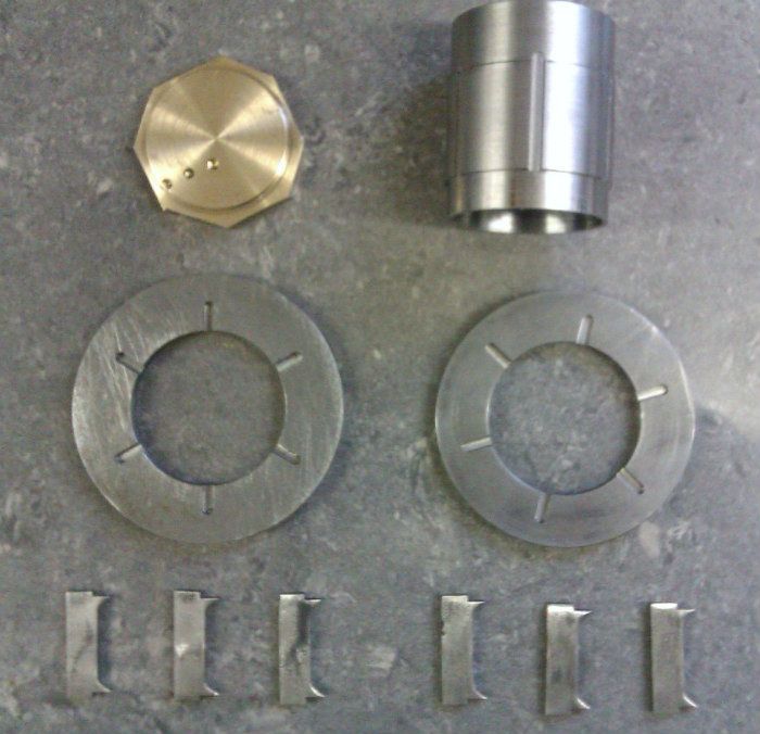
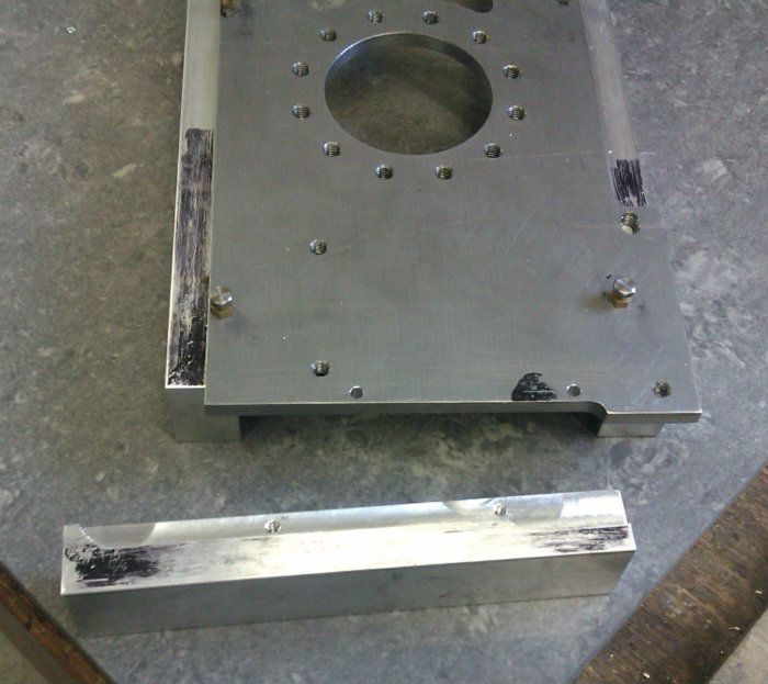
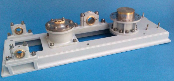
And here it is just about done except for a few odd holes and the above mentioned cutout.

IMAG0940.jpg


J
 
I am enjoying this and learning a lot as well. Thank you Jason.

Jim
 
Strap very well crafted. For those un-informed,will have a had time guessing that it was either a very well done investment casting
of semi hand mademachined.

Gus,now in Sydney.
 
The cylinder of this engine is raised above the bed casting buy what can be described as an upturned can with flanges top and bottom and a few webs thrown in for good measure. So starting off with a couple of squares of 5mm steel plate approx 3" square these were put in the 4-jaw and suitable holes bored.

IMAG0948.jpg


They were then held by the newly formed hole to turn the outside a little over finished diameter having first sawn the corners off.

IMAG0949.jpg


A piece of scaffold tube became the donor for the central tube

IMAG0936.jpg


Here are the basic parts, the old rusty pole turned out quite nicely and there is also a brass top that will form the cylinder bottom cover so no risk of rusting.

IMAG0950.jpg


The two rings were then held on the rotary table to mill some location slots for the reinforcing webs

IMAG0951.jpg


And matching grooves cut along the tube. As I don't have a tube centre for the R/T tailstock the angle plate up against the end of the tube reduces any risk of it tilting.

IMAG0952.jpg


The webs were machined from various offcuts of 1/8" plate, here they are all held together to have the radius cut using a home ground radius corner cutter from a blunt slot drill, I prefer this type of cutter to a ball nose one as they remove metal quicker.

IMAG0958.jpg


And here are all the parts ready to be silver soldered together.

IMAG0959.jpg


Seems a shame to make them all black and dirty

IMAG0961.jpg


A soak in the pickle soon sorted most of that out and it was then back onto the lathe to have all the finished surfaces machined to size.

IMAG0964.jpg


IMAG0969.jpg


After a final clean up I added fillets to all the internal corners, as these are quite hard to get at to sand rather than use JBWeld I opted for milliput which is more like a putty and can be shaped and blended before it sets, a wet artists paintbrush helps as well as a ball ended tool.

IMAG0978.jpg


And here it is with a bit of paint on.

IMAG0982.jpg


I'd like to say the elongated top holes are a special design feature but they are the result of not having the work on centre when setting out the PCD

J
 
Millput, wet artist's brush and ball ended tool eh, must remember that. It certainly did the job. This is a great learning experience Jason, Thanks.

Jim
 
The end frame pivots in a pair of bearing blocks, as they suited being silver soldered together I made the various parts from steel with a bit of machining allowance on the height.

IMAG1001.jpg


The semi-circular receess in the main blocks were cut by clamping the two blocks together and drilling then milling down the joint.

IMAG0995.jpg


And here are all the bits soldered together

IMAG1002.jpg


After a quick clean-up the tops were sawn off and then milled down to thickness. The holes in the base were tapped and those in the top opened out to clearance size.

IMAG1004.jpg


I could then bolt the halves together and bore the holes for the bearings.

IMAG1014.jpg


The final step was to add some thin brass to get the correct look around the fixing holes, drill and tap for the oil cup and then add some studs and bronze bearings.

IMAG1015.jpg


Finally add a bit of paint and we are one step further to completion, I think I will drop the nuts down to the next hex size as they look a touch big.

IMAG1036.jpg


J
 
And here are all the parts ready to be silver soldered together.
Seems a shame to make them all black and dirty
A soak in the pickle soon sorted most of that out and it was then back onto the lathe to have all the finished surfaces machined to size.
J

Jason, those are very nice looking joints & finished parts. I would really like to learn more about your your silver soldering setup & procedures one day... torch, solder, flux, cleaning & treating...
 
Absolutely loving this build! I am one of those quite readers on this site. I sit back and admire some of the approaches taken, especially when it comes to mimicking castings. I will keep saving away for my own machinery (after the wedding and whatever else gets put in front of them for me :) )
 
Masterful work Jason :bow:
 
Peter, there is nothing special about my soldering setup. 1" nozzle on a torch supplied from a 3.9kg Propane bottle. Esyflow solder, Tenacity No5 flux and a few odd insulation bricks. Chuck it into the pickle which is the dry acid crystals mixed with water for a while then quick scrub under hot water with a fine wire brush.

Back to the build

The old photos show a piece of diamond chequer plate below the beam suppot pivot that is missing from AM's model, this was most likely to give access to the air pump below the base. There are some sheets of so called chequer plate sold for models but they are not that accurate and even the ones for 7.25" locos looked too small so I had to make some.
Starting with a piece of 1/8" brass I used a 3/16 cutter in the mill to make passes 0.020" deep with a rib of 0.020" wide between at an angle of 15deg, its not that easy to see due to reflections and tool marks but hopefully the second shot shows whats going on.

IMAG1017.jpg


IMAG1018.jpg


Next the piece of brass was stood up in the vice at an angle of 15deg the other way and a 0.025" slitting saw used to cut grooves at the same spacing that teh milling had done cutting through the ribs and into the base metal by another 0.020". Thats a bit of 1/2" flat bar I have got the brass clamped to as it would flap about too much on its own.

IMAG1021.jpg


Some 0.020" brass sheet was held between scraps of MDF and the same slitting saw used to cut narrow strips off the brass, these were over height at about 1/16" wide.

IMAG1023.jpg


These strips were then given a light coat of soft solder paint pushed into the saw slots and heated to melt the solder

IMAG1024.jpg


After a clean up they were machined back to height, the stray ends removed and the plate cut to final size

IMAG1026.jpg


A quick spray of primer and it looks half decent.

IMAG1037.jpg


As a side not the set up for cutting the brass strips could also be used to trim a larger piece of timber down to provide nice miniature planks for cylinder lagging, these are the MDF offcuts but I don't think that sthe right material for this particular engine

IMAG1025.jpg


J
 
That last post, my friends, defines "Attention to detail".

Very impressive level of dedication! :bow:
 
Nice work Jason,

It's always a pleasure to watch you work!

Dave
 
Now that is a very ingenious way of producing plate. I’ll be filing that one away for future use!

Rob.
 
Nice work Jason,

It's always a pleasure to watch you work!

Dave

Hi Jason,

Me too. You have set a good example which I will follow. My work is sloppy and not great to look at. Perhaps I should not gone on to take my equivalent of HND(Higher National Diploma,Engineering) and moved on to a desk/field job after completing apprenticeship.

Gus.
 
You may remember that back when I started on the base in this thread that I mentioned the sides would be built up with aluminium strip, well I happened to be passing my local stockholders and poped in to pick up the ali.

First job was to machine a 1/16" rebate into the top edge to locate it against the edge of the steel plate, I could then attach the ali with some countersunk screws.

IMAG1027.jpg


Following that the mill vice was clamped down with a bit of packing under one end so that it was slightly tilted, this gave me the desired "draught" angle to mimic a casting and the majority of the waste was machined away with a 5/8 end mill.

IMAG1029.jpg


That was followed up with a 1/2" ball nose cutter to put the cove on the bottom edge, the top was rounded with a home ground cutter.

IMAG1030.jpg


This left the ends square so they went back into the mill to have the profile put on the ends.

IMAG1032.jpg


I also cut some pockets into the edging under the bearing supports to take brackets which were given a shallow concave face. The rebates of the four edgings were coated with a slow set epoxy adhesive and screwed into position, the joints and screw holes filled with JB Weld which was also used to stick the brackets in place
.
IMAG1033.jpg


Once set the JB Weld was cleaned up, fillets added with Milliput and then the whole thing given a quick blast of primer, here it is with a few of the other parts in place.

IMAG1103.jpg


IMAG1104.jpg


J
 
It's really starting to take shape, beautiful work!
 
One of the larger fabrications on this engine is the rocker frame that supports one end of the beam, I started off by making the bearing housings that go at the top of the frame, these were machined down to 7/16" from 1/2" material and drilled tapping size then I started to machine the semi circular ends.

IMAG1043.jpg


A drill was placed in the bolt holes to act as a pivot and the curve roughed out in stages and the facets were then filed smooth

IMAG1044.jpg


The blocks were then cut in half and a male and female formed and the holes tapped in the body and opened up to clearance in the caps

IMAG1047.jpg


The hole for the bronze bearings was then drilled and finished with the boring head

IMAG1049.jpg


A small amount was skimmed off the bottom half so that when the cap is screwed down it will grip the bearing

IMAG1050.jpg


A hole was tapped in the cap to take an oiler

IMAG1051.jpg


Finally a spigot was formed on the end of the bearing block to lacate in the side members of the frame

IMAG1078.jpg


I had been trying out a few methods to make the oval sections for the frame and in the end settled on compressing 10mm steel tube in the vice followed by a quick lick on the linisher, this is a short sample and is what I used for the sides and X braces, the two curved parts were machined from flat bar and bent to shape

IMAG0911.jpg


Jumping forward a bit all the tubes were cut and scribed to fit together and then placed into a jig made from some structural C section which was notched to hold two rods at the correct spacing.

IMAG1110.jpg


Some fire bricks were packed up in the channel to help support the parts, correction fluid applied to the two rods then the bearing blocks were clamped to these and all the parts assembled before being silver soldered together.

IMAG1082.jpg


IMAG1085.jpg


After a bit of a clean-up, lick of JB Weld and a coat of primer this is how it turned out.

IMAG1105.jpg


IMAG1106.jpg


Next up are the beams
 
Back
Top