Briesch; 1/3 Associated Tips and Tricks

Home Model Engine Machinist Forum

Help Support Home Model Engine Machinist Forum:

This site may earn a commission from merchant affiliate links, including eBay, Amazon, and others.
Joined
Jul 31, 2010
Messages
306
Reaction score
70
Hi

I am looking for tips and trick for when I start machining my Associated castings. Pictures would be great.

BTW, I see the dates on the drawings are 1967 - 1969. They have been around a long time.

Thanks

Tim
 
Hi Tim,
I don't have any particular tips and tricks for machining this engine. It's pretty straightforward. I do have some pictures of mine and could take more if you needed closeups of some specific parts. The only thing I found with the Briesch drawings is there is more dwell time on the cam (to operate the points) than is required. By the way, do you have a points engine or an igniter engine?
gbritnell

associated hit and miss 1.jpg


associated hit and miss 2.jpg


associated hit and miss 3.jpg
 
George, nice looking engine. Those must be the original Briesch castings. It appears you have more room for the spark plug than we have in the new castings. I am at the point of making the spark plugs for my 3 engines.
Is it possible to get some details on your plugs and maybe a photo of the plug. What size thread?
Thanks

Tim, I'll try to get post photos of my setups for you tomorrow.
 
gbritnell said:
Hi Tim,
I don't have any particular tips and tricks for machining this engine. It's pretty straightforward. I do have some pictures of mine and could take more if you needed closeups of some specific parts. The only thing I found with the Briesch drawings is there is more dwell time on the cam (to operate the points) than is required. By the way, do you have a points engine or an igniter engine?
gbritnell

The 2 sets of castings I have are for the spark plug engines. Mike did not have any M&B cylinders in stock. I may look at purchasing a set at a later date.

I was told by an old tool and die maker that at 3 engines (or anything) that it was worth making good fixtures.


Tim
 
Hi Arv,
When Paul Breisch was selling his kits he also had spark plugs available. I don't know much of the history of these plugs but they have porcelain insulators and a ground strap for the spark. The are 1/4-32 thread which is a carryover from the old model airplane engine days. I have many hours on mine and haven't had any trouble with them. They do have a .375 hex as opposed to the .312 hex on the new Rimfire plugs.
George

REMCO PLUG 1.jpg


REMCO PLUG 2.jpg


REMCO PLUG 3.jpg
 
Here's a couple of pictures of the plug.
George

REMCO PLUG 4.jpg


REMCO PLUG 5.jpg
 
Thank you George. The reason I asked about the plug is that on my castings, that area of the head is about .800" thick. When I look at your plug and count the threads, it would appear the the thread is about 1/4' long. That puts the spark quite a distance from the cylinder. Am I looking at this right or have I got something all wrong? ???

I have always tried to put the spark into the cylinder if possible.
 
Hi Arv,
You're right about the length. It doesn't seem to hurt the operation of this engine but with the Little Brother the plugs comes in at right angles to the combustion chamber so it really shrouds the spark. I made one of my own plugs with a long enough reach to get into the pocket that leads to the combustion chamber. It probably wouldn't hurt to make a longer one for the Hired Man engine as it would kick up the compression a tiny bit.
George
 
Tim, these are a few tips that I use when working on castings.

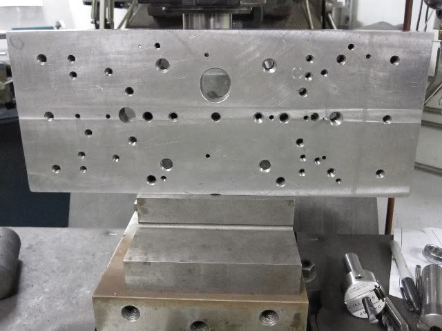
When I first started building engines from castings I made up a fixture plate. It was a piece of ¾ X 6 X 12 hot rolled steel. I fly cut it as flat & square as I could. I used this plate as a fixture for most of the setups on the base casting for most of my engines. So far I have built an Economy, 2 Atkinsons, 2 Red Wing Thorobreds, a New Holland, & now 3 Associated Hired Mans using this fixture. It is especially helpful when you are building more than one at a time. I highly recommend you take the time to build a similar fixture before you even start these engines.

You can see this one has had a lot of use.

FixtureA1.jpg

The first thing to do with new castings is to compare them to the print. I usually do a quick layout with a height gage on the castings to make sure all the functional holes line up with the details on the castings. They don't always line up good and you may have to adjust the pattern a little to allow for the variations in castings.

The first machining operation is to flatten the base and square it up with the rest of the casting. This usually amounts to shimming the casting from end to end and side to side so that all the details are in their proper alignment. This can be time consuming but pays off in the long run.
Clamping sometime requires some imagination and isn't always the most secure setup. By taking light cuts on the casting you can usually get by without problems.

InitialSetupA.jpg


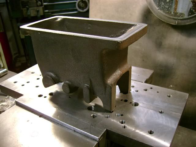
Once the bottom is flat and square with the world, I turn the casting over and take a light cut on the bearing journals just enough to make a couple parallel surfaces for later setups.
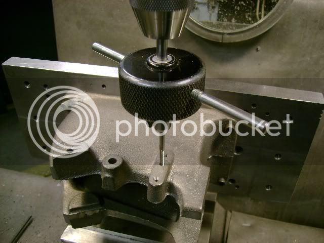
Next I remount the castings on the two parallel surfaces and an adjustable third point for leveling.

This setup is used to locate & drill the 4 corner mounting holes as well as adding 2 small dowel pin holes. (This operation probably could have been don on the first setup but I like to double check the squareness of the bottom surface before I machine any additional details.) The 1/8 dowel pin hole do not go through the castings.

After this operation is done, put the same hole pattern on the fixture plate. This time drill & tap the mounting holes. From now on you can locate & mount the castings on this plate & be certain of the location. You can switch from one casting to the other for each operation and be certain that you are on location. It will cut the machining time for the second casting down to a third or less as most of the time is in the initial setup.

ThreePointSetupA.jpg


MountingHolesA.jpg


Following are photos of some of the various setups I used for my 3 Associated engines.

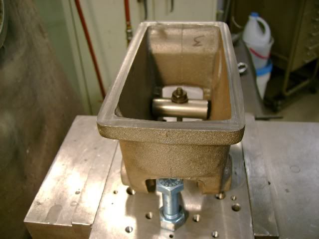
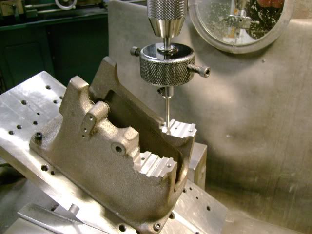
Drilling and tapping some of the details on the side of the casting. I also drill & ream a small locating hole for the bearing crank bearing.

LocatingDetailsA.jpg


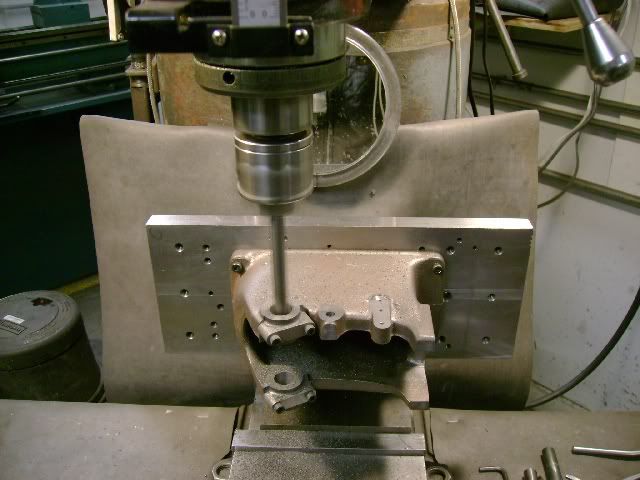
I setup at the proper angle for the bearing journals. Machine the journal surfaces down to 1/2 the diameter of the small locator holes.

BearingJuornalsA.jpg


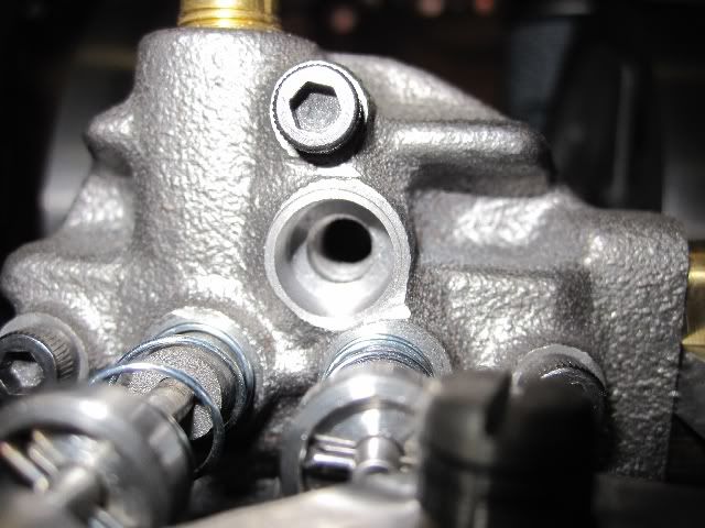
Next bore the bearing holes on location and to size.

BoringJournalsA.jpg


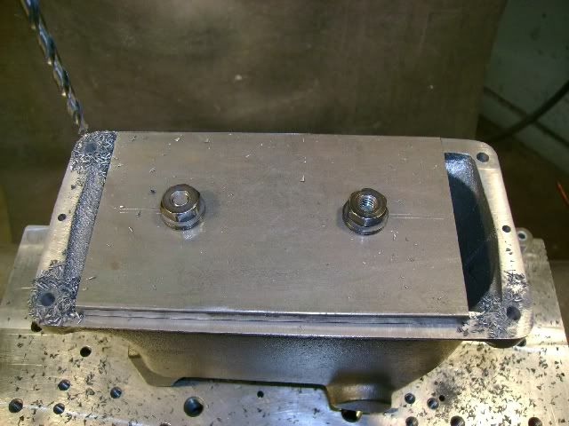
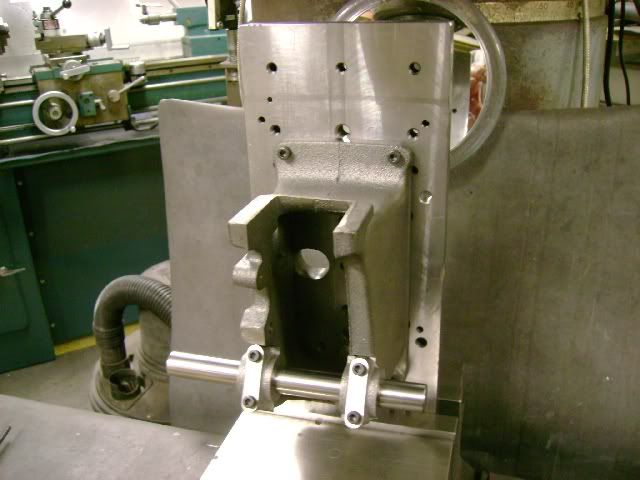
The fixture is also used to machine the details in a vertical position.

VerticalSetupA.jpg


I think you can see the advantages of spending the time and ewffort to make up a fixture. It is very fast & easy to switch back and forth from two or more casting have be on location for each operation.

Hope this is what you were looking for. If there is anything more I can help with, just ask. I am nearing the completion of my engines.
 
Hello Arv,

Very nice job on the fixtures. I am a great believer in fixtures, even for many one off parts. Besides, figuring out the fixture is half the fun.

Regards,

Chuck
 
Thanks for the comment Chuck.

George, I ended up counterboring the head so I could reduce the length of the 1/4-32 threaded portion as well as the smaller diameter insulator. I still ended up with over 1/2 inch of threaded area.

AssociatedHeadA.jpg

I tested out the plug with a S/S CDI unit I had on hand. The plug worked fine.

AssociatedPlugA.jpg

Tim, you might run into the same problem. If you want to follow my plug design, I can send you a print.
 
Hi Arv

Great pictures and tips. Is the cam gear shaft hole the master point on this engine? That would mean that one would have to indicate off of it when boring the main crank shaft bores for the correct gear backlash.

One question. Why do you drill and tap the holes before milling the surface flat?

Thanks

Tim
 
The cam gear hole and the crank shaft hole have to be "dead nuts" so either can be the master. I just kind of established a good center average of all the details and then worked from there.

As far as drilling and tapping before finish machining the surfaces, I waited until a new vertical center line was establish and the bearing journals were secured in place before I machined those surfaces. I guess it is just a personal preference.

I think you will find there is very little machining stock on the two vertical details in front where the cylinder bolts to. That will somewhat establish the center point in that direction.
 
Got the first Associated engine (air cooled Hired Hand) started & running. I temporarily mounted it on a platform I used for one of the Red Wings. Also borrowed the CDI unit from the Red Wing.

The engine started right off. It was running about 1000 rpm, too fast for a hit & miss. I adjusted the governor springs as loose as I could get them but couldn't slow it down that much. I had a supply of very weak springs so decided to try them. These springs along with some adjustment on the lock out arm spring and the engine was running at 400-500 rpm and would cycle quit a few revolutions before firing again.

I am going to bring the other two water cooled Hired Man engines up to this level on a temporary setup before I start putting the finishing touches on them.


Since I built my H2O-cooled Hired Man over many years, borrowing machine time in shops at work, I had to have an easy way to hold and set up the base casting repeatedly. I used a philosophy similar to putputman's. I bought a big toolmaker's knee from Enco and doweled the engine base to it. I made sure the knee was accurate, so then I could set it down on any face and ensure the machined faces would end up square and parallel. I ended up having the knee ground to get it accurate enough.

I put a hall-effect ignition on my engine. There is a magnet embedded in the cam gear, and also one on the pushrod as a battery saver (so the ignition doesn't fire when coasting).

I made pretty nearly every screw, nut, and spring in the engine. I made the heads of the hex screws to scale. In my opinion, socket-head capscrews on these kinds of models look bad.
 
Hay Arv, pictures of encouragement. Thanks.
 
I have a set of castings, Been under the bench for 30 years with a set of Wyvern drawings. Now when I got them out to start building obviously the castings are for a Briesch Associated and not the Wyvern.
They look exactly like yours pictured. Now does anyone still sell these kits? What I need is a set of drawings. I don't like to start a new friendship asking for help but I don't know where else to turn.

Thanks for any help,
Bob Sanders

Phoenix, AZ area
 
I have a set of prints and castings of the same vintage. The prints are yellowed, faded and delicate. I will try to copy them and see what I get.
 

Latest posts

Back
Top