Brian's Donkey Engine

Home Model Engine Machinist Forum

Help Support Home Model Engine Machinist Forum:

This site may earn a commission from merchant affiliate links, including eBay, Amazon, and others.
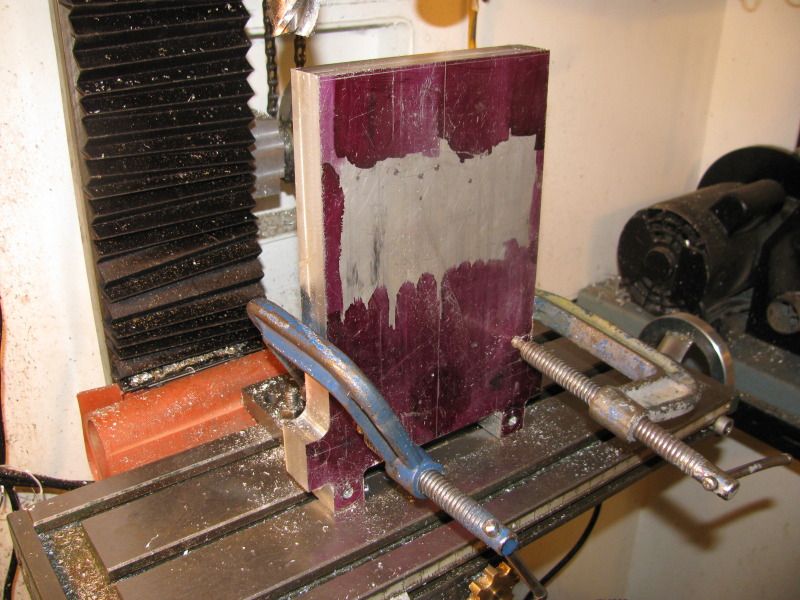
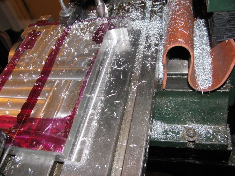
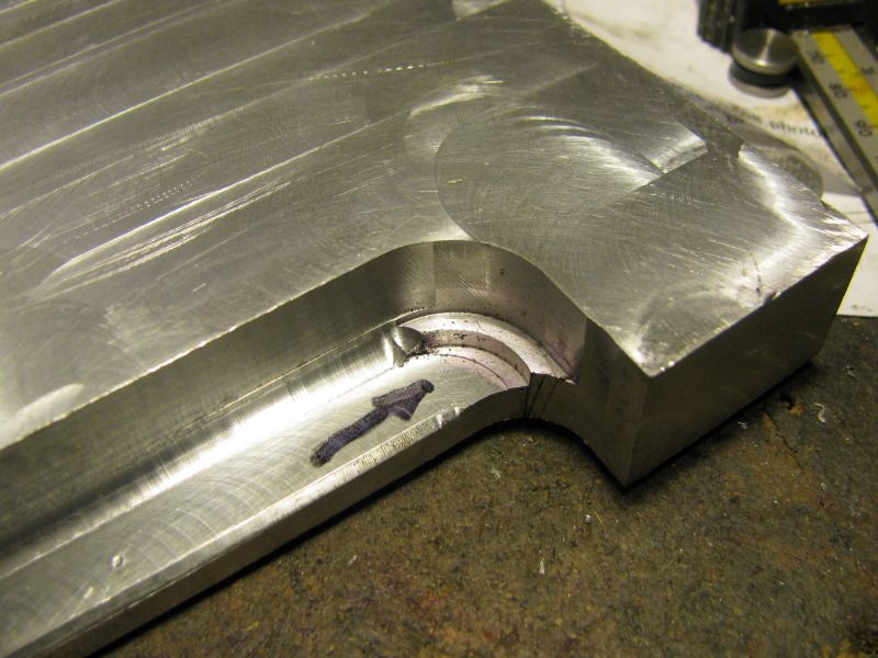
I was cutting freehand. I find that using a fence just makes the problem of kickback worse. I had a death grip on that chunk of aluminum during the entire cut process. Jerry---I was given two of those motors by someone who once worked for Superior Propane. They had a maintainance protocol that dictated changing out the motor every two years whether it had been ran or not. He had a whole damn shed full of them. I wish now that I'd got a dozen of them.
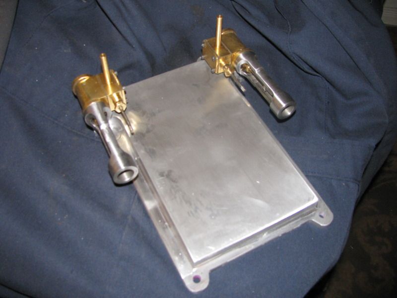
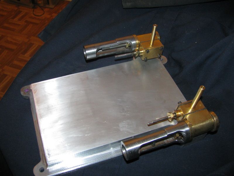
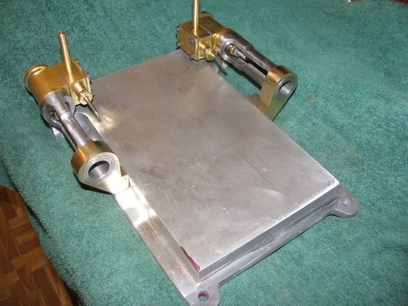
 
So here we are, after a part days machining, with the outer profile mostly finish milled. I have one big old angle plate that I bought when I bought the mill.----It gets used only rarely, but when its needed, nothing else would work as well. Tomorrow should see most of this base finished, if my arm doesn't fall off from turning the feed handles back and forth.
basepartlydone001.jpg
 
NUTS!!! A little checking of my endmills has shown me that I can't put that lovely fillet around the bottom lip of the base. The height of the vertical portion above the flange is 5/8", and the 3/16" ball end mill I have only has a short cutting area about 3/8" long from the very tip before it flares out to 3/8" diameter to fit the collet.
 
Come on Brian, you know the solution. You are working again. Money spent on tooling is always a good investment.

Jerry
 
Brian take a blunt straight cutter, long series if needs be and just grind the corners off to a small radius, I do it a lot to get internal fillets and they rip through the metal far faster than a bull nose cutter. The grinding does not have to be spot on and is easier done on a 2 flute cutter than a 4 flute. Here is one in action.

ignitor4.jpg
 
Brian, you might want to try a router bit for a nice profile in aluminum.

chuck
 
Near as I can tell, that new 1/4" ball end cutter that I bought is going to work real slick. I got called away today right in the middle of milling my baseplate, but tonight I snuck into my shop and kind of squeezed in behind the mill to get this shot. I have never milled to an inside corner with a radius in it before. Its kind of a combination of tricks and simple math. I know the total depth of cut is going to be 5/8"-----But the radius on the ball is 1/8"----Therefore I can only cut to 1/2" depth with my 3/4" two flute cutter. Then I have to offset my cutter from the vertical wall by 1/8" and cut another 1/8" deeper. Then I put in the 1/4" ball nose tool, zero off the bottom of the cut, back up 1/8" in Z axis, wind the cutter over untill it just "kisses" the vertical wall, then start taking passes advancing the ball nosed cutter .015 at a time untill I reach my zero on the z axis. It works---but its kind of like walking a tight-rope balancing 3 plates while blindfolded. The picture doesn't show it really well, but I wasn't about to tear down my set-up to get a better picture.
ballnosecutter001.jpg
 
Suffered a minor catastrophe this afternoon while machining the end of the baseplate. The cutter dropped down about .100 while finishing off the flange on the end opposite the boiler. Cutter dug in, pulled down, blew the fuse in the mill!!! Not a terrible catastrophe----but a maddening one. I planned on painting the base anyways, so I filled up the almost perfect 3/4" diameter circle with J B Weld tonight and will let it set overnight with a 100 watt bulb close to it. Other than that, the baseplate is turning out quite nicely. The 1/4" ball nosed mill I purchased has put a lovely 1/8" fillet on the inside corner of the flange along both sides and across the end opposite the boiler, and I bought a peice of 1/8" square HSS to make a radius cutter where the radius blends into the curve up near the end where the cylinder mounts. I will post a picture of it when I have built it and succesfully used it.
 
Sometimes I paint myself into corners. It is QUITE EASY to design something in 3D that looks really good, but is damn difficult to actually recreate in metal. This is one example, where the black arrow points to. After running my filleting end mill along the inside corner to create that nice "as cast" looking fillet, I had no idea how to chase that fillet around the corner. I had left the material there to fillet----Just didn't know how to go about doing it.
RADIUSCUTTINGTOOL006.jpg
 
So----I built myself a filleting too. I milled a slot into a chunk of 3/4" diameter cold rolled, 1/8" wide. I had purchased a piece of 1/8" HSS yesterday, so took it to my grinder and formed a 1/8" rad on one end. I had drilled and tapped my 'special tool' for a couple of #5-40 set screws, so that secured the HSS in the tool, then I trimmed off the other end.
RADIUSCUTTINGTOOL004.jpg

RADIUSCUTTINGTOOL001.jpg
 
And "Voila!!!!!"----the results are not outstanding, but beat the Hell out of anything I could have done with a Dremel tool and a burr. I thought as I was finishing this up that I could probably have achieved the same results with my boring head if had wanted to sacrifice one of my boring tools by grinding a radius on the carbide tip. This is still going to require a bit of dressing with said Dremel tool and burr, but its been a learning experience!!!
RADIUSCUTTINGTOOL009.jpg
 
Where there's a wil there's a way, bit of blending and a thick coat of paint and it will be looking fine. :)

This is another advantage of the old cutters with teh corners rounded off they can create a larger radius though you probably would not have got a 1" cutter into your machine.

Can also be done by bolting the work to a rotary table with the centre point of the curve set to the axis of the RT and then just use the same cutter that you did the straight run with.

J
 
Thats a world of pain mostly behind me!!! The base looks great, but it stetches my capabilities as a machinist.----But probably thats a good thing. I have some minor cosmetic work yet to do on the base, but that can wait untill final tear-down, when I paint the base.
basefinished001-2.jpg

basefinished002-1.jpg
 
Think I'll go here next. I'm burned out from working on that base. A quickly "nested" layout shows that I can get two brackets out of a crusty old piece of brass that I have left over from some other job.
scroungingbrass001.jpg
.
 
Brian Rupnow said:
And "Voila!!!!!"----the results are not outstanding, but beat the Hell out of anything I could have done with a Dremel tool and a burr.

Brian - Good job on the radius issue. The problem is after all that work you go and cover it up with the cylinders where no one can see your handiwork. We used to have a saying that relates to that. It is like peeing in your pants in a brown suit. It gives you a warm feeling but no one notices.

Keep up the great work.

Harold
 
WARNING--WARNING--WARNING---I THOUGHT I HAD MENTIONED THIS AT THE BEGINNING OF MY THREAD, BUT I CAN'T FIND IT NOW.---THIS DONKEY WILL RUN ON COMPRESSED AIR, NOT STEAM. DUFFY HAS POINTED OUT THAT THE BOILER IS TOO SMALL IN RELATIONSHIP TO THE SIZE OF THE CYLINDERS----MY APOLOGIES TO ALL WHO THOUGHT THIS WAS A TRUE STEAMER--BRIAN
 
Slowly, Slowly Pokey Monkey----The crosshead guide supports are taking shape. I have to figure out next if its worth setting up the rotary table to round them off, or to do it freehand on my beltsander. The problem with doing them on my rotary table is that I would have to Loctite a shaft into the bores to hold them. The trouble with doing them freehand----Well we all know the trouble with that!!!
CROSSHEADTUBESUPPORTS001.jpg

CROSSHEADTUBESUPPORTS004.jpg
 
I decided to take the easy way out----So I walked them out to my big vertical belt sander and freehanded them. Then a little file work, and Hey Presto!!! Now I have to set about making the wee buggers right and left hand.
CROSSHEADSUPPORTS-3001.jpg

CROSSHEADGUIDESUPPORT-A-1.jpg
 
Hi Brian

Very nice work :bow: :bow: :bow:

I'm enjoying this.

Cheers

Rich
 

Latest posts

Back
Top