Brian's Donkey Engine

Home Model Engine Machinist Forum

Help Support Home Model Engine Machinist Forum:

This site may earn a commission from merchant affiliate links, including eBay, Amazon, and others.
This is coming along very nicely! Love it! :big:
 
Well, this should be interesting, to say the least. In right and left hand as well-----------
BEARINGSUPPORT-2-1.jpg

BEARINGSUPPORT-2-3.jpg
 
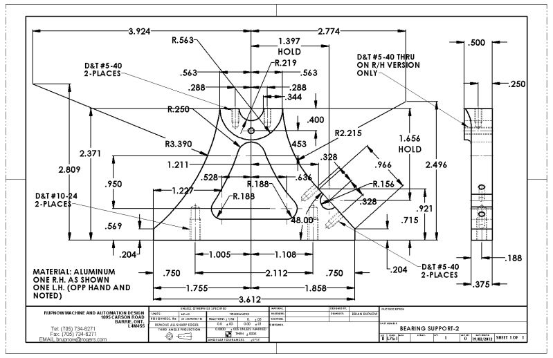
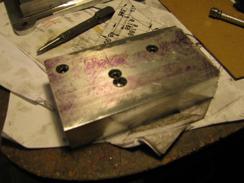
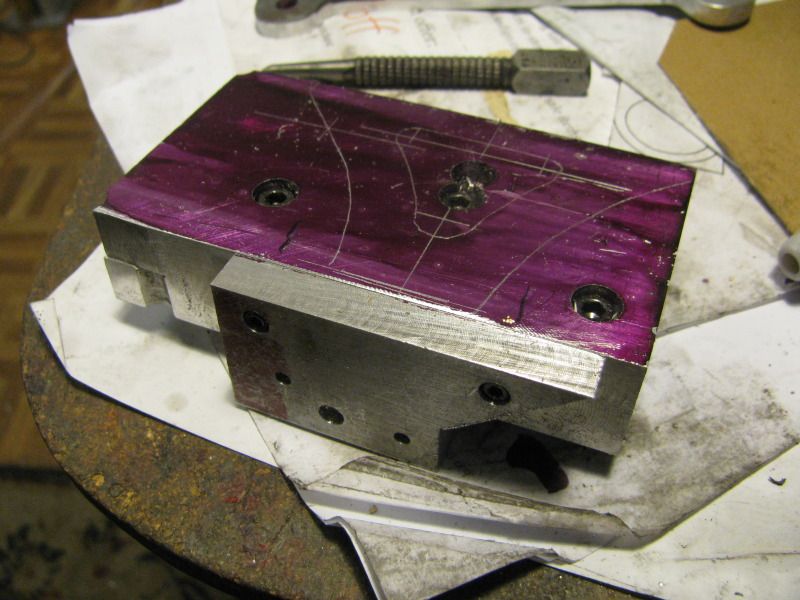
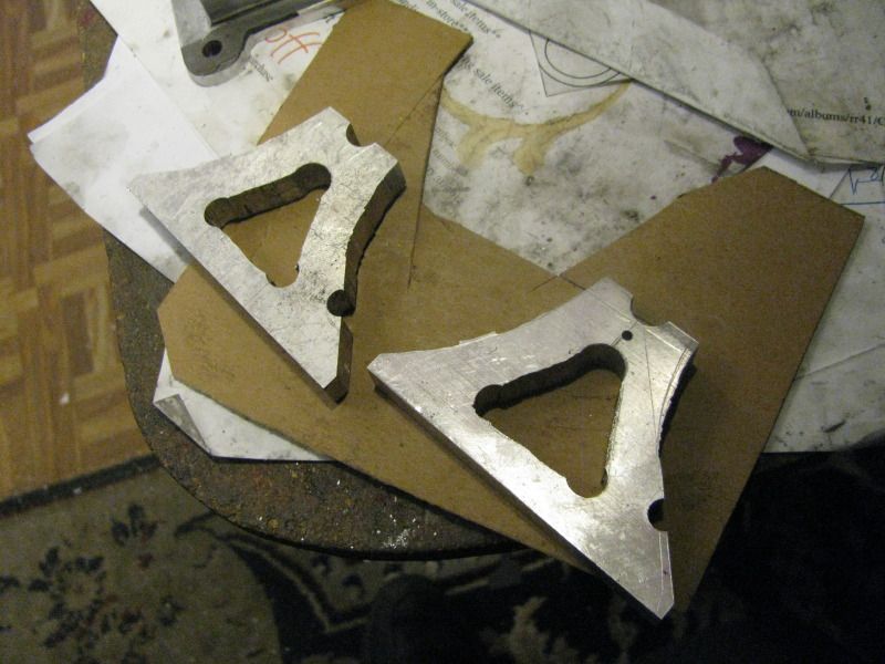
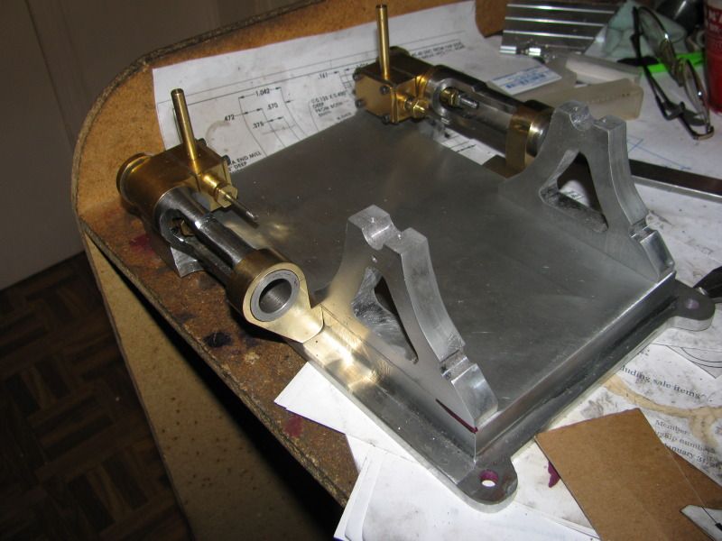
And how does one go about making something with such wildly imaginative radii on it? Well, its like this. I needed to come up with the geometry in order to "draw" the part. Yes, even in 3D there are rules, the first of which is that you have to be able to draw the object in 2D before extruding it into the third dimension. And the geometry used in creating that drawing is composed of lines, arcs, circles, and angles, same as any mechanical drawing. 99% of the shape is purely cosmetic. The only really important geometry on the part is that the base must be flat, the top parallel to the base, and the relationship of the upper and lower bearing radii to the base and to each other. The cutout in the center, and those big swooping radii on the outer edges are flights of fancy, pure and simple. They serve no purpose, other than "eye candy". So---How will I proceed? Well, first of all, I'll print the drawing off at 1:1 scale, and glue the print of the main profile to some cereal box cardboard. Then I'll cut it out with my scissors. I will take a piece of 1/2" aluminum of sufficient size, I establish one straight edge on the aluminum plate or bar stock as my base, and set it up laying flat in my milling machine, parallel to the bed, with a piece of sacrificial aluminum underneath it. Using the hand dials (I have no electronic read-outs) I will pick up "zero" from the edge I have designated as the "bottom" and drill the two holes which appear as "half holes" on the perimeter of the frame. In the same set-up I will drill the 3 holes that form the corners of the window in the center. I will then stand the piece of aluminum on edge, with the "bottom" resting on the mill table and clamp it to an angle plate and mill the top surface to a height of 2.371" from the base. I then remove it from the mill and coat it with layout dye, and lineing my cardboard cutout up with the bottom edge and the previously drilled holes, I will trace around the cardboard with a scribing tool. I will cut the two major outer radii using my bandsaw, and the curved lines connecting the 3 "window" holes will be cut out with my sabre saw. The only important feature on the piece other than the bearing holes and the top bearing pad is the area to either side of the pinion shaft hole, which must be a straight line (not a radius) and must go exactly thru the center of the hole at the angle specified on the drawing. I will leave a bit of extra material in that area and set the piece back up in my mill to finish machining those areas. The material which is removed from the face of the plate to leave a raised "boss" at the upper mainshaft bearing will be dealt with using the milling machine and rotary table.
 
If you have to make two plates that have identical outer contours, then what better way to start out than by bolting the two plates together, with zero clearance holes. I counterbore the material so I don't have bolt heads to contend with in subsequeunt operations. I have found that no matter how carefully I line the plates up and how tightly I clamp them before drilling, there will always end up being some minor misalignment on the two edges which are supposed to be in line, so I always take a light pass over both edges AFTER the are bolted together.
BEARINGPLATES-1002.jpg
 
Somebody is going to ask me "Why did you bolt that extra piece of plate to the edge of my bearing plates?"---Well, since I was scrounging thru my junk bin to find these two plates, they are just a tad to small. You will notice that the top "half hole" is only about 0.100 from the top edge. I can't drill a half hole---only full sized holes. And there is absolutely no way to drill a hole that close to the edge of a plate without having the drill break thru, catch and break the drill, or drill a very crooked hole. With that extra piece bolted on there, I can drill and ream my hole with no fear of that happening (part of the hole will now be in that scrap of plate). Then I unbolt the plate and throw it back into my junk bin.
PLATEBOLTEDON2001.jpg
 
So there they are!!! A world of filing awaits me, but they are identical and all of the critical surfaces and holes are an exact match.
BEARINGSTANDS-4001.jpg
 
The bearing stands are 75% finished. I still have a bit of light sanding to do, and some tapped holes, but I'm happy.----Brian
BRGSTANDSFINISHED-1001.jpg
 
Guess I'll go here next. I have to have some way to clamp the brg. stands to a shaft to spin it in my rotary table chuck, and this is probably the best way---seeing as I have to build them anyways.
WINCHSHAFTBRGCAP.jpg

PINIONSHAFTBEARINGCAP.jpg
 
I'm getting better at this radius business. I have to tap some holes for the pinion shaft bearing caps and to hold the stands to the base, and they're done. Once I get the bearing stands finished, I can either flip or flop.---That is---Move to the gears and winch drum and clutch, or finish of the engines and get them running.---Not sure which yet.
BRGSTANDSWITHRADII004.jpg

BRGSTANDSWITHRADII003.jpg
 
And for tonights enjoyment and entertainment (after 8 hours at one of my "real" jobs)----A potload of tapped holes and a nifty set of pinion bearing caps!!!
PINIONSHAFTBEARINGCAPS001.jpg
 
I've been thinking of what to do next, and have decided that since the success or failure of the entire project depends on the engine, that is where I should go next. This is a relatively simple twin cylinder self starting engine, with what amounts to an EXTREMELY long center section to the crankshaft. Over the next few weeks I will be concentrating on finishing and running the engine before moving on to the winch. I'm undecided as to whether or not this winch should have a brake. There is no room for a brake at the end where the clutch is, but at the other end of the winch drum, if I remove the flange and replace it with a disc of cast iron, then a band brake can run on the outer surface of the disc. Obviously, the clutch and brake should both be operated from the same side of the engine, so that means there would be some kind of cross rod running through the base from side to side so that both levers can be operated by one man from one side. On one hand, this adds a fair bit of complexity to the build, but on the other, since I made this a single drum donkey I have saved myself a lot of work, so it kind of balances out. What is your opinion fellows?----Brian
 
Brian

From what I have seen, it was done both ways. On smaller units, the clutch and brake were at the same end of the winch with the clutch expanding internally and the brake wrapped externally on the same drum. On larger hoists, the clutch and brake were at opposite ends to prevent heat from one function causing slipping on the other. You can do it either way and still be right. But I don't think I have ever seen a hoist without some kind of brake or pawl.

I doubt that a hoist or donkey was ever designed or built with a solid base casting like yours so passing a brake actuator rod through a fabricated base frame would not be a problem. You could easily pass a rod through the solid base but the brake mechanism has to be inside the bearing stands. How about running the rod through a couple of pillow blocks on the top surface of the base?

Jerry
 
Think this is where I'll expend my efforts today. These flywheels are smaller in diameter than I am accustomed to. I know for a fact that a double acting twin cylinder engine with the crank throws 90 degrees out of phase will run with no flywheel at all, but its pretty "Hirky Jirky". I have made these flywheels as thick as I can without compromising the look of the donkey.
DONKEYFLYWHEEL.jpg
 
It's looking nice, Brian.

Chuck
 
And this is what I spent the day at!!! The pictures are somewhat "posed" with a piece of 1/4" cold rolled holding them up. I am happy with what I've done today, but consider----Its 4:30 now and I started these this morning at 8:30 !---No wait, thats a lie----I spent a couple of hours at least tapping the base for the bolts from underneath that hold the bearing stands in place, and the threaded holes in the sides of the base that hold up the brass crosshead guide supports. Still, darned expensive flywheels if I had to pay somebody to make them. Last week I bought a set of small broaches at BusyBee tools and this might be my first opportunity to broach something.
flywheelsfinished--maybe002.jpg

flywheelsfinished--maybe001.jpg
 
Brian

You don't need to overdo the crank thickness. Because the winch gear is always engaged, it's rotational energy is added to the crank web. The problem is having room for the crank web between the con rod and the eccentric strap. Plus there is precious little room between the crank web/flywheel and the bearing stands for the eccentric.

Jerry
 
Jerry---I assume you meant the flywheel thickness. You are absolutely right!!! There is such a lack of room between the flywheel and the bearing stand that I have changed the design of the elliptical cam to be a hubless style. That is what let me gain enough room to fatten up my flywheels a bit.
 
I've been looking at the pictures posted above, feeling that something just didn't look right. It just hit me---when I had the engines off this morning to drill and tap the base, I swapped sides unknowingly when I reassembled it. The valve bodies are supposed to set inboard, not outboard. No grief---I just switched then back to being in the right place.
 
I'm going to try a BIG STRETCH now and do something I have never done before. As I said earlier, I purchased a small broaching set from Busybee tools, and a big arbour press, and I guess the time has come to try it out. I didn't want a hole through the face nor the side of my brautiful flywheels, but a little sneaky cad work tells me that if I go in through one of the windows at 26 degrees I can get a tapped hole directly over the key. Wish me luck.---Brian
DONKEYFLYWHEEL-1.jpg
 

Latest posts

Back
Top