Brian builds Atkinson Engine

Home Model Engine Machinist Forum

Help Support Home Model Engine Machinist Forum:

This site may earn a commission from merchant affiliate links, including eBay, Amazon, and others.
Great video Brian. Wasn't shaky at all. And, it's great to see the little engine workin' hard. :)

Todd
 
Beautifully done Brian and loved the video.i know you had a run with it, but you came through great. Congrats on completing it.

Don
 
Brian,

I've been away from the forums for a while as work has taken away all of my free time for a couple of weeks, but I am glad to see you tamed this one. Very nice work as usual :)

Congrats on another one!
 
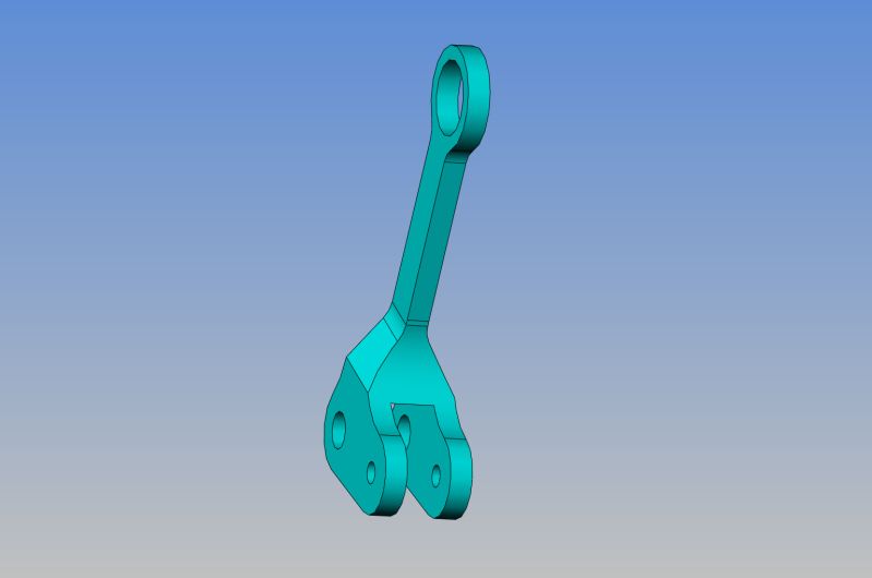
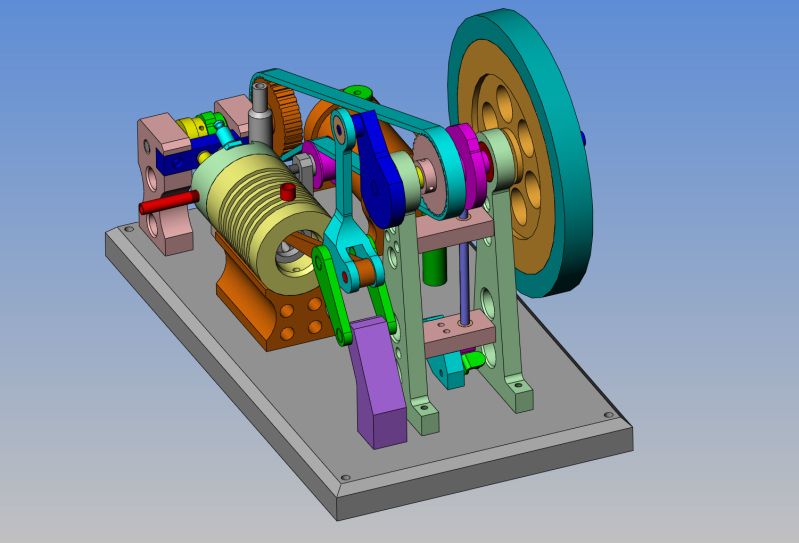
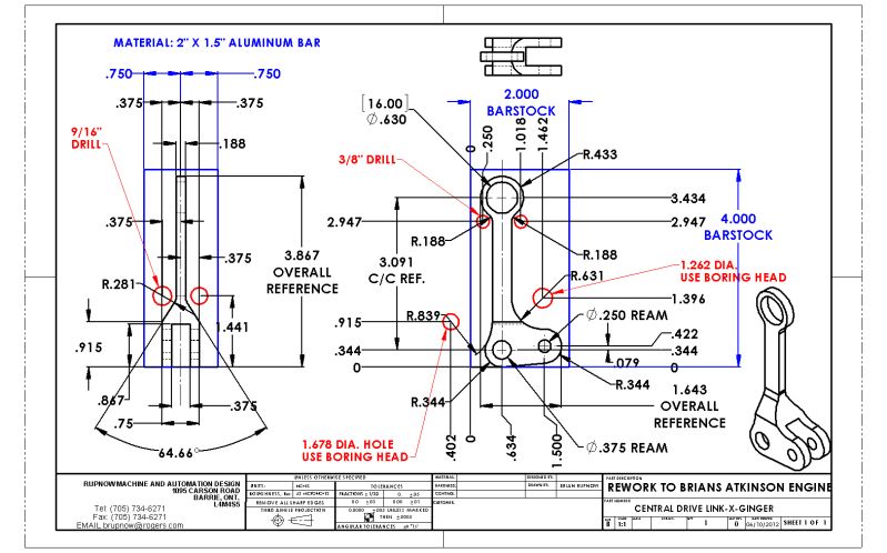
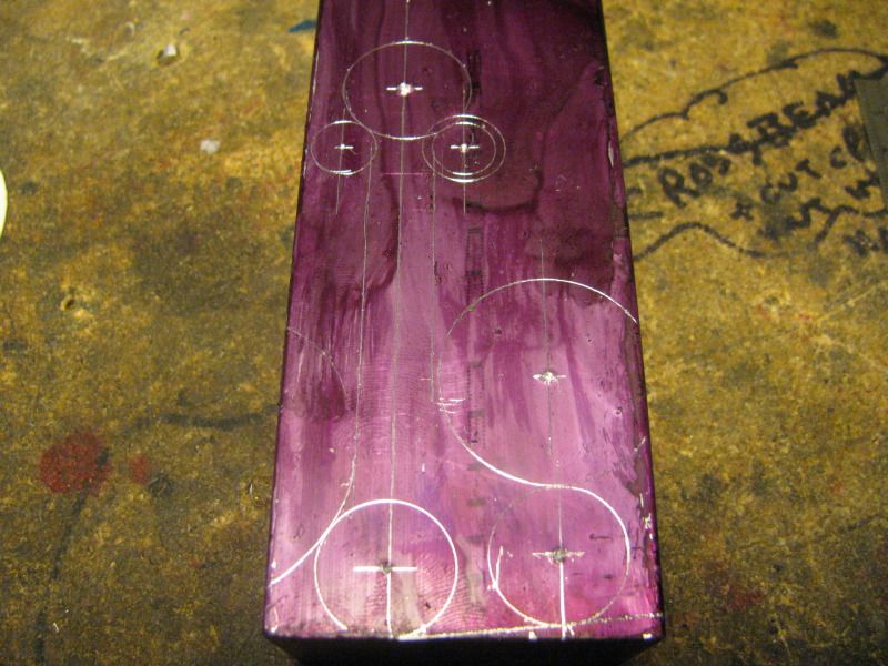
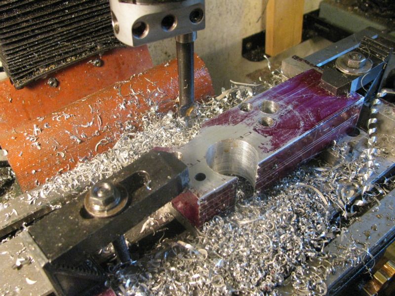
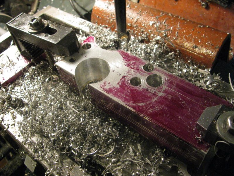
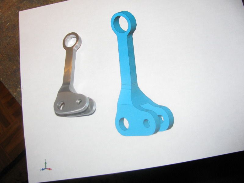
Although the engine runs very well, I have discovered a flaw in the basic design. The linkages including the intermediate link, stationary link and the "throw" of the flywheel shaft are all offset from each other and from the connecting rod. (This can be seen very clearly in the very first post in this thread) At very low RPM as seen in the video, the engine behaves quite well, but as speed is increased, the offsets in the linkages create a "side throw effect" for lack of a better phrase, and the engine quickly becomes very noisy and acts as though it could quite possibly "throw a rod" or one of the links in an explosive way. I have been doing a bit of research to see how others have handled this, and found a very good video"Gingery Atkinson Cycle Engine" on Youtube. This engine was designed with all of the linkages centered about the connecting rod and cylinder, and I'm sure gives superior performance through a much wider RPM range. I am quite busy right now, in the middle of a conveyor design job, but when things slow down a bit, I am going to see if I can redesign some of the parts in my linkage train to be centered, similar to the ones in the video. Nothing other than these linkages and possibly the flywheel shaft have to be redesigned/remade so that should make a good follow up to this build.
 
Last edited:
You are correct. The engines don't like to run fast, I have just finished the Ginery Atkinson cycle engine and when I try to go above about 450rpm it starts to jump all over the place.
I think that this is a design flaw in all of them.
 
Great video, but after watching it, I MUST now make one of those awesome Jacobs ladders... I'm off to search for plans now, unless someone can point me in the right direction.
 
Last edited:
Hi Brian

Fourth or fifth time through the video now. I could watch the Atkinson and it's Jacobs Ladder until I went dizzy, It's amazing and very addictive.

I see why you can't go past it without firing it up.

Right back to the workshop with renewed vigour, now I've had my "fix"

Regards Mark
 
Finally, tonight I squeezed out a couple of hours design time----and---I can do it!!! I can redesign/remake about 4 parts and have everything centralized. Surely do end up with some strange looking parts, but I can keep everything on a common centerline.
CENTRALDRIVELINK-X-GINGER.jpg
 
Brian, sorry for the unrelated side question. But I really like the drawing format of how you overlay raw material stock in one color, and what looks like tool diameters (for drills or mill radius etc) in another color along with their corresponding reference dimensions.

This is Solidworks, correct? I'm a SW 'up-and-comer' & I'm attempting something similar using seperate drawing tabs. Getting through it, but not quite as nice as yours. If you ever care to show a brief tutorial of your workflow in a seperate pots, I'd be interested to see.

2012-10-06_120637.jpg
 
Petertha--Are you in North America? Yes it is Solidworks. I have worked with it every day for 13 years, and I also teach D modeling with Solidworks.If you are in North America, email me your location and phone number. My contact info can all be found on my website. If I had to recommend one book that is the absolute best book I have ever seen for learnhing Solidworks, get "Inside Solidworks" second edition by David Murray. ISBN#0-7668-2348-2 by Oxford Press. I still refer to it for some of the more obscure commands that I don't use very often.----Brian---And by the way, the red circles indicate the centers of larger radii.
 
Can you see it?---It's in there!! I always lay out the object to be machined as a visual reference. Don't worry if some of my circles aren't "bang on." I'm using an old drafting compass with two points and no lead to scribe those lines, and the diameters are not perfectly "on spec." Ultimately, I always use an edge finder in two planes and then use the X-Y dials on the milling machine table to position the part for all drilling operations or cuts with the boring tool. The layout simply provides me with a "back-up reference" in case I miscount the number of turns that I turned one of my dials. Since the table moves 0.100" for one full turn of the dial, any miscounts will show up right away. After all the holes are drilled, I will use my rotary table to cut the outer diameters to size, wipe off the first coat of layout dye and recoat the part, then use a straight edge and a scriber to connect the edges of all the holes and/or major diameters.
NEWDRIVELINKLAYOUT001.jpg
 
Since I had to download all the pics off my camera to get the picture in the preceding post, I thought that I would show you a picture of a maple tree in my side yard that I planted last spring. Normally maples don't turn this bright shade of red until we have had a good overnight frost. We haven't had any frost here yet, but this tree seems to have went ahead on its own.
NEWDRIVELINKLAYOUT003.jpg
 
Brilliant work Brian. You are not gonna let this engine kick your butt are you. :D

Ah yes. The early bright colors. We're getting them down here in New York too. My wife says that this predicts a heavy winter for us. She's been using that theory for the last 8 years. She's never been wrong. So, get you snow shovels and blowers ready.

Todd
 
Here we are with all the holes drilled, reamed, and bored in the first side. My little mill isn't real crazy about all those interupted cuts done woth the boring head to create the radii in the sides of the part, but it does it. The swarf created during these operations wipe off all the layout die, but I can still see the scribe lines in the aluminum. There are only 3 critical holes, and two of them are reamed, so that takes the pressure off me. The third hole though, since it is metric and I don't have metric reamers has to be bored. I always find boring with a boring head to be a rather uncsientific machining operation. I get close to finished bore size, within about 0.030", then sneak up on it by one or two of the division lines on my boring head, with each pass. Each division takes .002" more out of the diameter of the hole being bored, but the damned division lines are so small and close together that I have to have a jewlers loupe to see them. I made up a plug on the lathe and turned it to exactly 16mm and used it to 'feel" my way the last couple of passes. When it felt like it might go into the bore, but wouldn't quite, I stopped boring. Any thing left in the bore that has to come out will be taken out with emery paper.-----And Oh yes, if you look close, you will see a peice of "sacrificial" aluminum plate 3/8" thick under each end where the part is clamped!!!
NEWATKINSONLINK002.jpg

NEWATKINSONLINK001.jpg
 
With those interrupted bores, an old trick is to clamp or bolt a piece of similar material (Aluminum in this case)on the outside of where the hole goes giving you a non-interrupted cut. A lot easier on the machine and your ears.

Also on those .002 boring heads, try a magnetic base and a .0005 (½ thou) indicator. Gives 1-1 readings. If it doesn't make sense at first, try it.
 

Latest posts

Back
Top