Brian builds a Corliss

Home Model Engine Machinist Forum

Help Support Home Model Engine Machinist Forum:

This site may earn a commission from merchant affiliate links, including eBay, Amazon, and others.
It's Sunday here Andrew. Nothing is open until tomorrow. My nut and bolt suppliers are pretty good. If they don't have it in stock they can usually get next day delivery from Toronto.---Brian
 
Today I have very little to show---but I did do some work. I machined the piston rod, and I machined the cross head. I have found from experience that two parts that are joined together with a thread, that are supposed to end up concentric to each other, seldom are. To give me a better chance of concentricity, I hold one part in the lathes 3 jaw chuck, and one piece in the tailstock chuck, give a good application of 638 Loctite, screw them together, and leave it to cure overnight. The cross-head is marginally over-diameter. Tomorrow I will hold the piston rod in my lathes 3 jaw and carefully machine the cross-head until it is a smooth sliding fit into the cross-head guide.
9ngmUH.jpg
 
I have found from experience that two parts that are joined together with a thread, that are supposed to end up concentric to each other, seldom are.

Sorry, Brian, but I'm a little unclear here. Are you saying the two parts are to have a continuous threading so that when you put the fastener in, it doesn't push them apart? Is this procedure to set the two parts up to tap the threading?
 
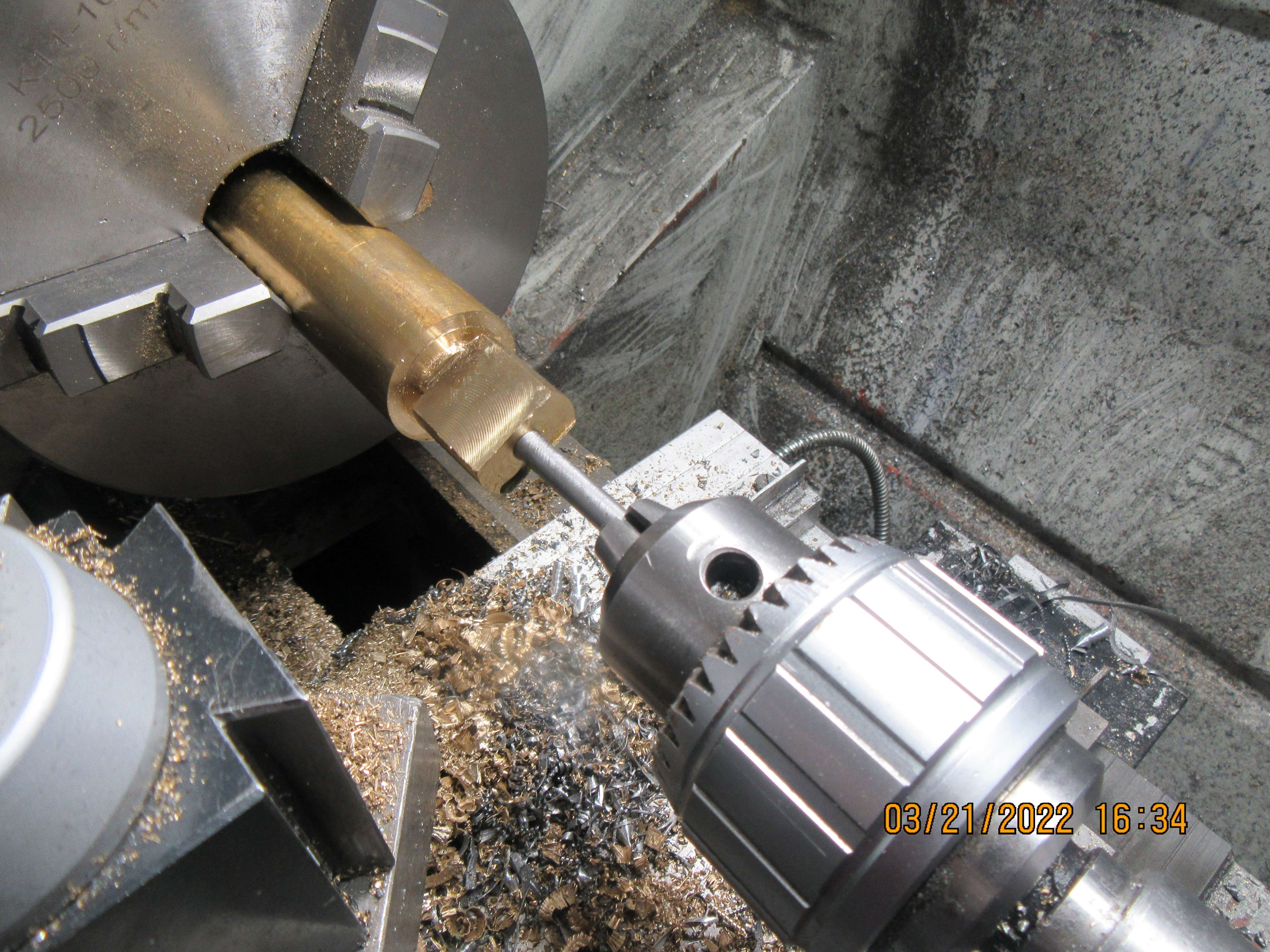
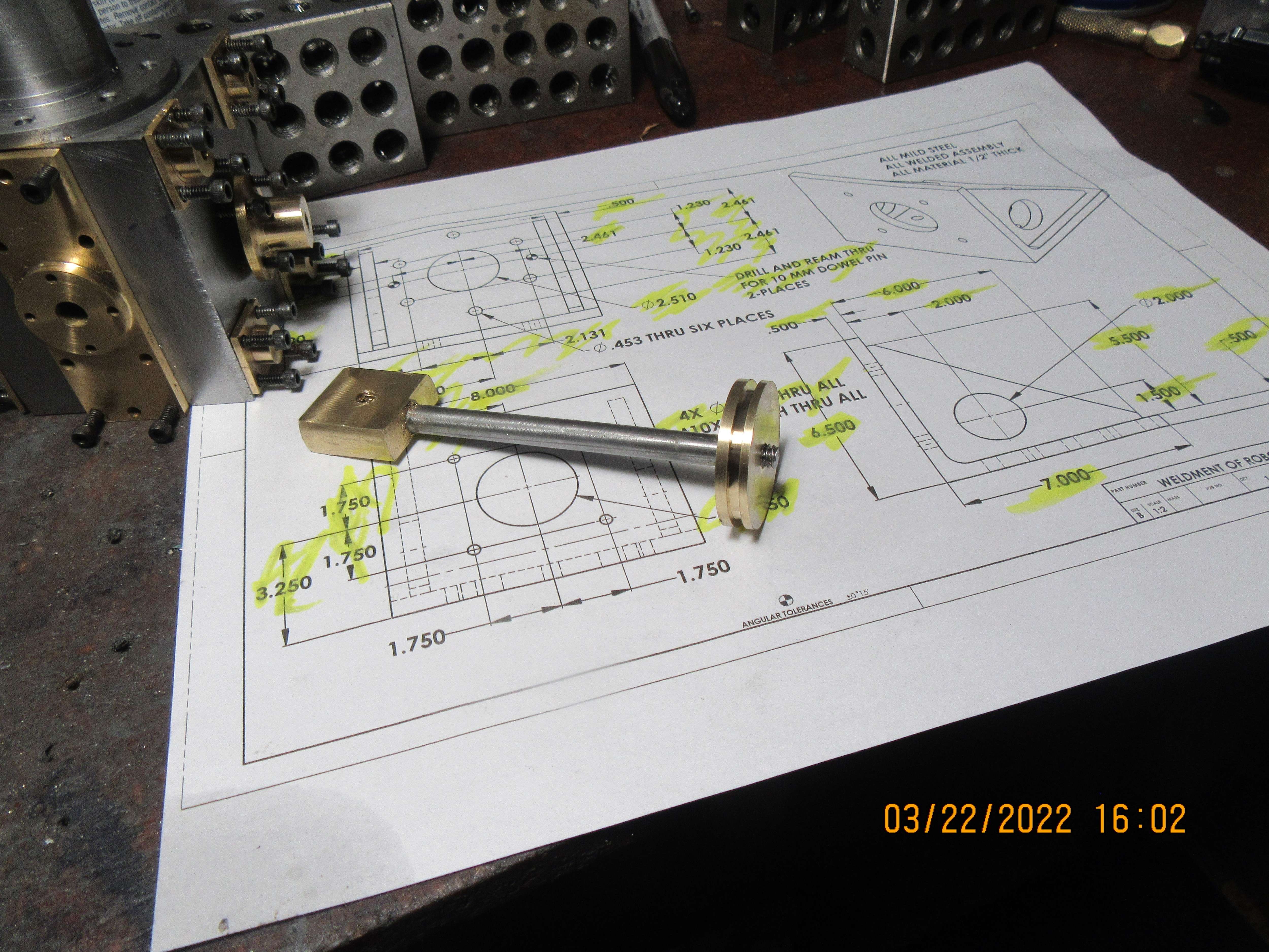
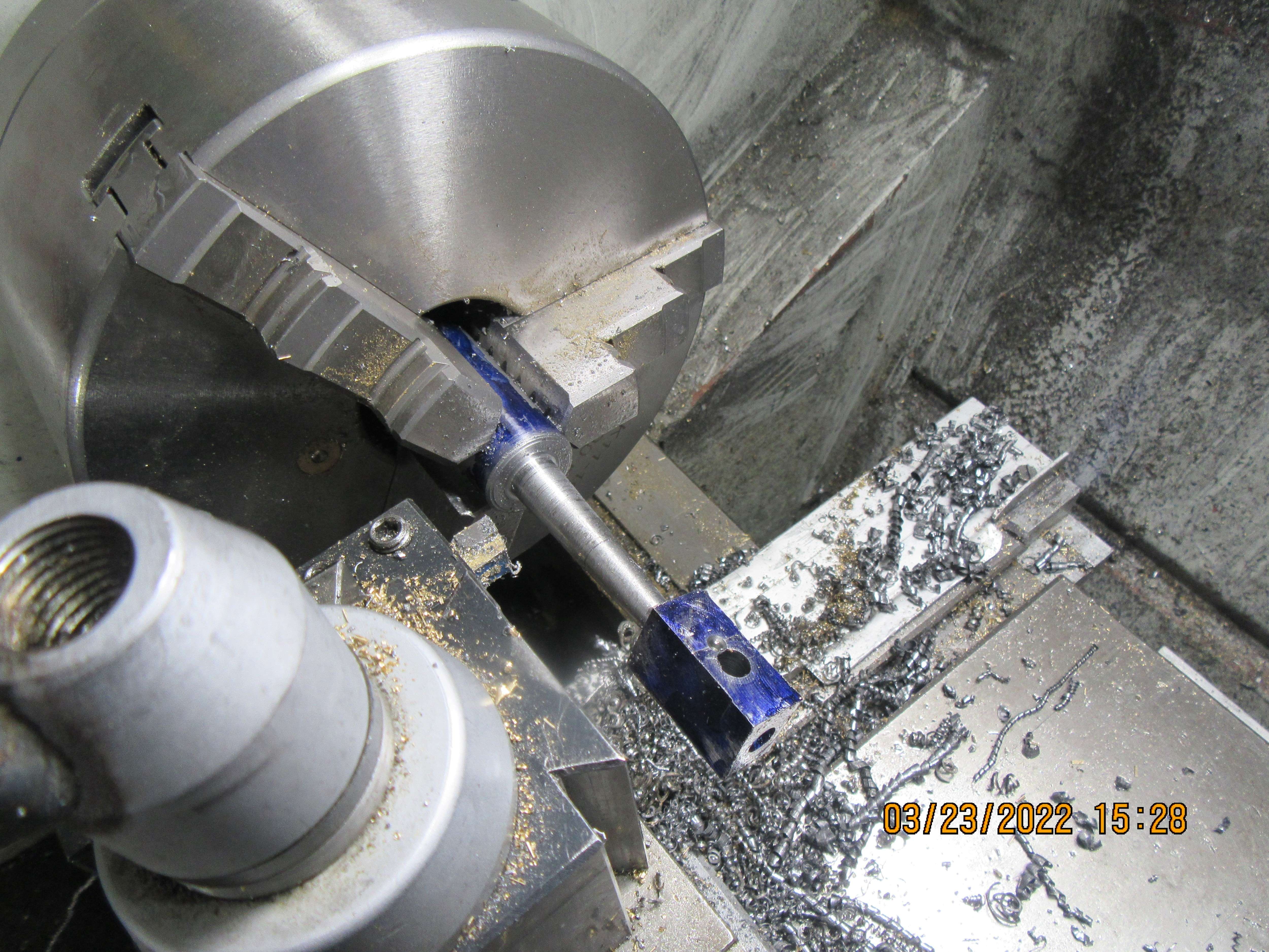
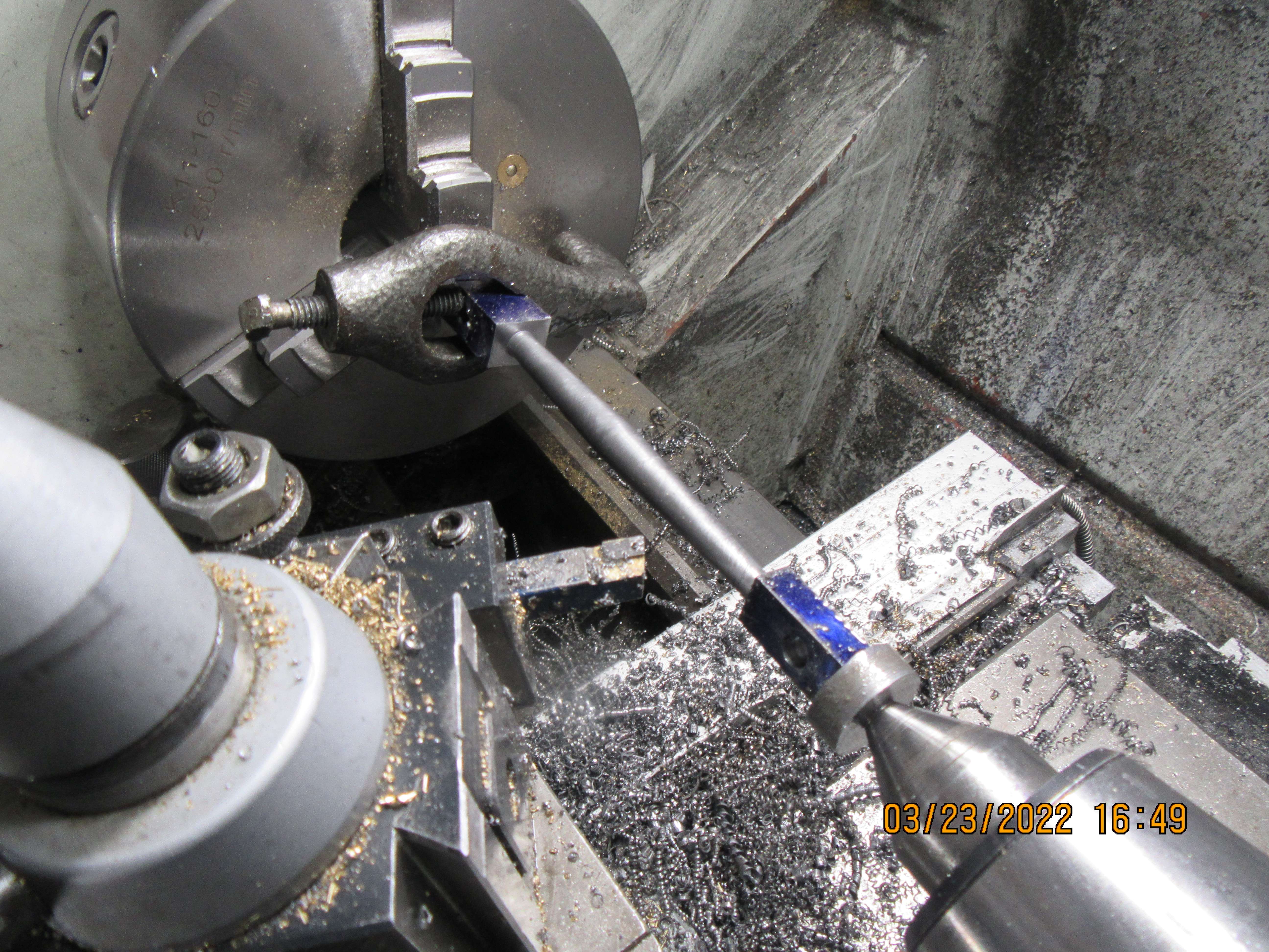
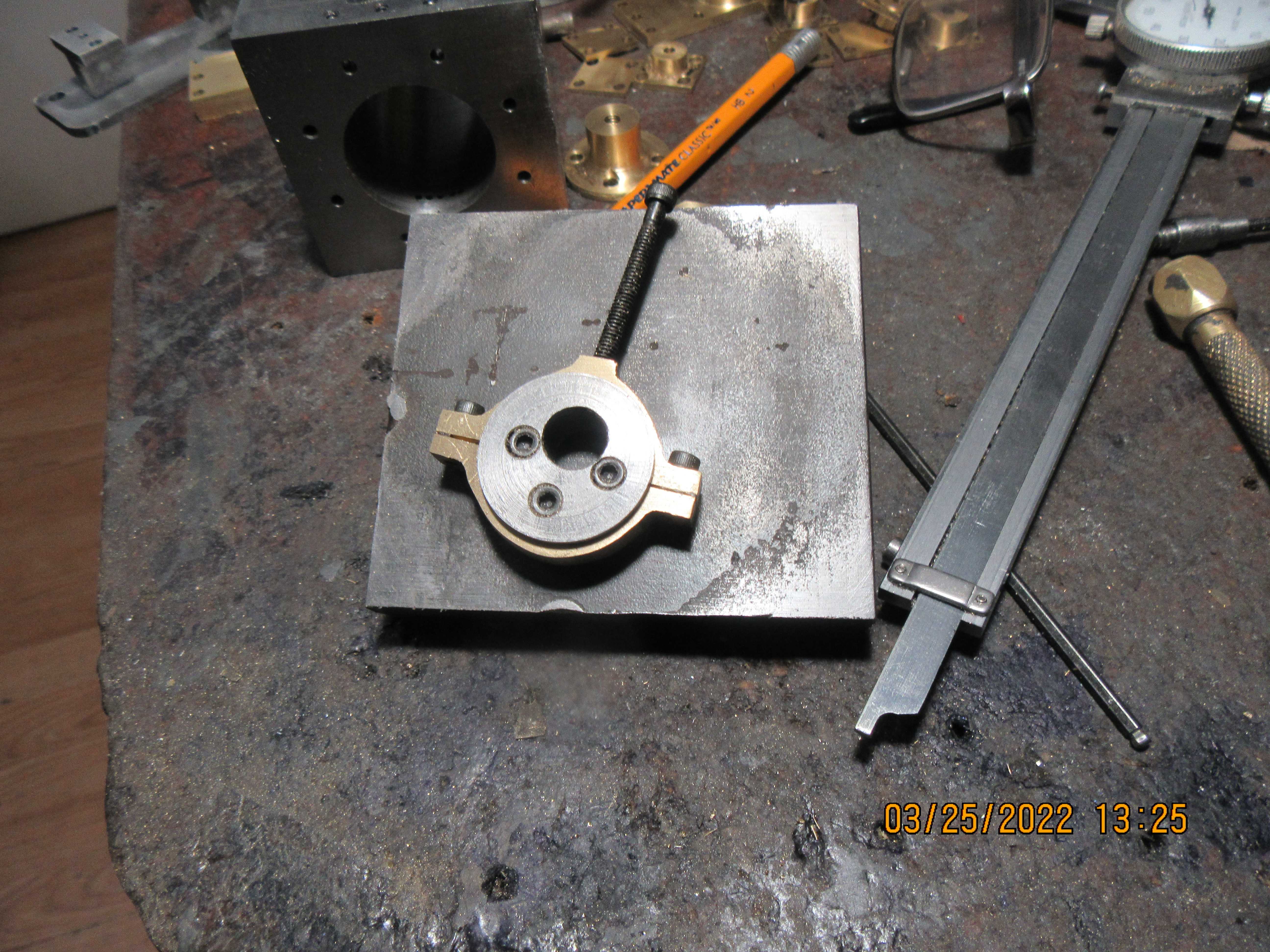
Bob--in a perfect world, if you cut a thread on a rod, and cut the same internal thread on a round piece that the rod screws into, the two pieces would be concentric. If you cut these threads with a lathe, then they might be. However, if you cut the threads with a tap and die, the threads will never be perfectly aligned with the axis of the part which the threads are cut in. What this means is that although the parts are firmly attached to each other because of the threads, the axis of the two components won't be perfectly aligned. On something like this piston rod (which is guided by the cylinder end cap) and the cross-head (which is guided by the cross-head guide), you want to aim for the greatest concentricity that you can achieve. These parts were threaded with a tap and die, then coated with Loctite and screwed together, then held in the two chucks to perfectly align them as the Loctite dries.
 
Last edited:
Thanks Brian.
Obviously, the final concentricity comes from the accuracy of the 3-jaw chuck holding the shaft, while you carefully machine the cross-head to size. I would be happier if I had a "truly concentric" 3-jaw chuck, or collet holder, but I don't have that luxury. Therefore I would have made the OD of the cross-head, and in the same setting bored it to an interference size for the shaft, then press-fitted the 2 parts, using the tailstock. - Just an alternative to cope with my 0.001" out-of-true chuck... A tiny fillet bead of silver solder would help lock the press-fitted parts, if I had any doubts about the strength of the press-fit. - I presume the same will apply to the piston after fitting through the end plate and gland.... Or something? I look forward to this.
Thanks Brian, always good to learn from your expertise. Much more real than a text book!
K2
 
Today it was back to "one part a day" mode. I had time to make my piston, and then got a call from a customer for design of a robot end effector to pick up aluminum roll bars for hydroforming. I might make the gland which screws into the rod end of the cylinder tonight if I have any energy left.
wj1CgJ.jpg
 
Interesting approach regarding locking the crosshead to the piston rod. The way it generally is described by all the old masters and more recent makers is that it is best to fit the oversize piston to it's rod and then hold in 4-jaw, split bush or collet and machine the piston down to size so it is concentric to the rod and do not remove it after that. Reason being is that the cylinder bore and hole in the end cover are the closest two parts so there is little room for error if they the piston/rod assembly is not concentric.

Also on many and engine a screed on crosshead is used to allow the builder to adjust the length of the rod so that the piston can be set to move equally about the cylinders ctr line so that is left with a usable thread and fitted with a locknut

One really needs to have one end that can be taken apart so the engine can be assembled and the cross head is the usual candidate. If you can
t get a thread true and don't need length adjustment then a reamed hole and spigot on the rod works well and can be retained with a taper pin

Maybe with you new tap guide you will be able to get a truer thread in the crosshead, also do you use a tailstock die holder? One other trick is to use a fine pitch thread as it's less likely to wander than a coarse one.
 
Today we have something new--for me anyways. Turning a taper using the top slide. I haven't done this before, and it works well, even if it is a bit tense. Being very, very careful that the turning rectangular end of the con rod doesn't hit the toolpost. I'm almost finished this first end of the con rod. I got to hold one end in the chuck for this first end. I have drilled both ends of the blank for a center, so the second end will be turned between centers with a lathe dog.
gwywJ1.jpg
 
This is the set-up for turning the second half of the tapered con-rod, complete with lathe dog.---And no, a pig doesn't live in my lathe but sometimes it shore looks that way. I do clean up between engines.
whm7T2.jpg
 
This is the set-up for turning the second half of the tapered con-rod, complete with lathe dog.---And no, a pig doesn't live in my lathe but sometimes it shore looks that way. I do clean up between engines.
whm7T2.jpg
Makes it look like it is used.
 
So, what did I make today?---Not much really. Spent the morning going to doctors appointments---got a needle to prevent pneumonia, got a needle to prevent shingles, set up appointments to see other doctors. Came home, eat lunch, and then went down to my little shop and built an eccentric. You can't see it in the picture, but this is a very special two part eccentric that has the far side flange bolted on with three #40 shcs. About half way thru the build of this eccentric, which was made two part so that I could make a one piece eccentric strap, I realized that it was a great idea but there wouldn't be any way to reach the grub screw to set the valve timing. Well POOP!!! Decided that since it was half finished, I might as well keep working and finish it, but will still have to build a two piece eccentric strap. You can see in the picture that I also finished the gland that screws into the rod end cylinder cap. I think the only things left to make are the eccentric strap and the valves. Wow!!! I won't make the wooden base until I'm sure that the engine runs.
KXOO0b.jpg
 
There is an absolutely stupid amount of time required to make an eccentric strap. I worked from 9:00 this morning until 2:00 this afternoon making this one part. Maybe this afternoon I can see about making the valves.
oeB7lc.jpg
 
Bob--all I made today was the eccentric strap. The other parts you see were made on previous days. I spent some time this afternoon applying J.B.Weld to the face of the flywheel where I had welded the spokes, filled a couple of holes on the base that I had drilled in the wrong place, and healed up a center drilled mark on the connecting rod where I almost drilled a hole in the wrong place.
 
Thanks for sharing this build Brian, I am really enjoying the ride. It is gratifying to see that I am not the only one that makes errors, even the experts do on occasion.
 
Solid progress, Brian. As Purdue used to say, "It takes a tough man to make a tender chicken." All your hard work and attention to detail pay off in spades when your engines are finished and run. This is going to be one pretty engine!
 

Latest posts

Back
Top