Brian builds a Corliss

Home Model Engine Machinist Forum

Help Support Home Model Engine Machinist Forum:

This site may earn a commission from merchant affiliate links, including eBay, Amazon, and others.
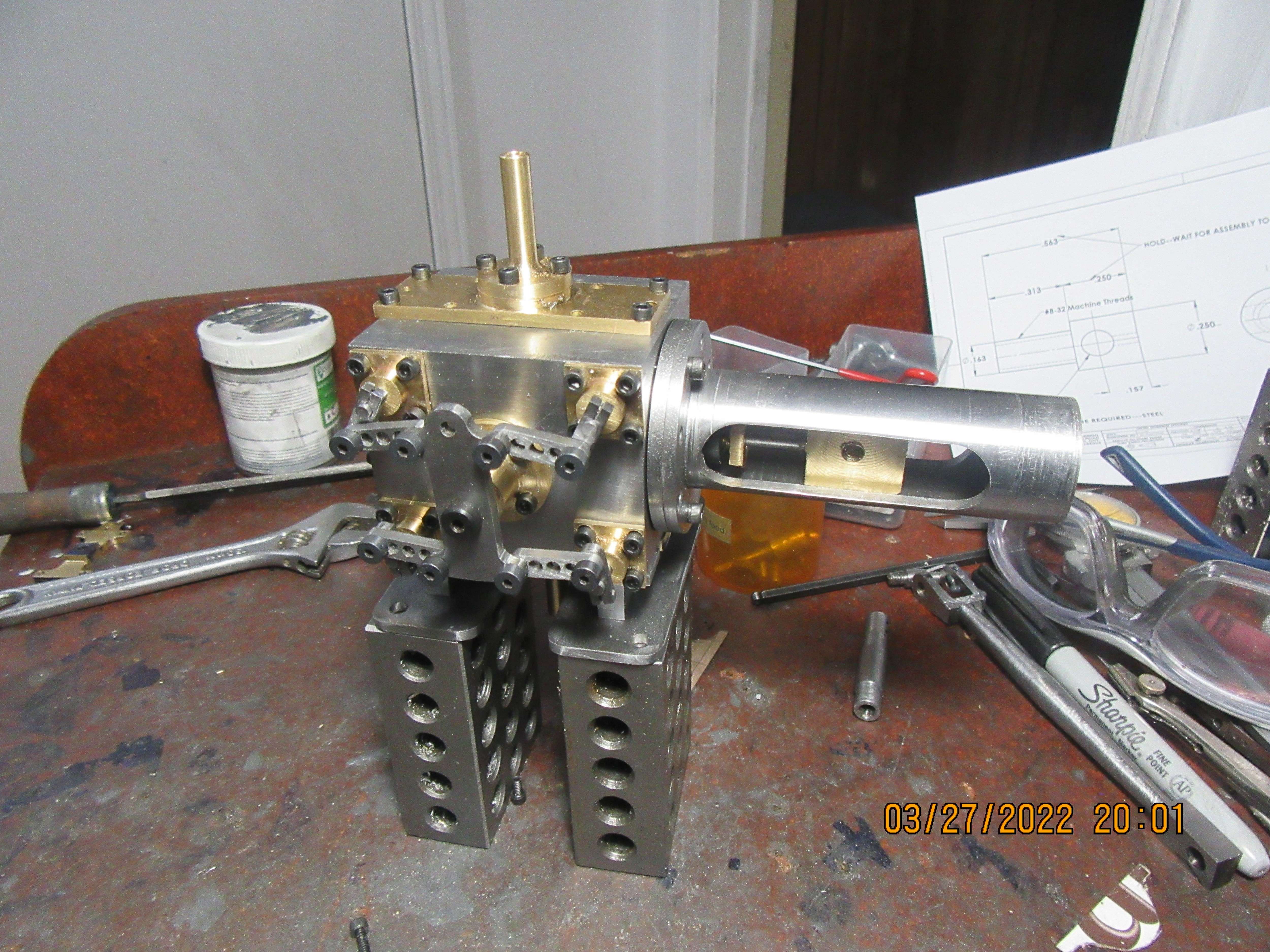
Liar,Liar, Pants on fire---I said yesterday that I only had the valves left to make. A closer look this morning showed that I had yet to make the air intake and exhaust pieces. Got it all sorted out today anyways. I think I'm going to remake the "wobble plate" that sets on the front of the cylinder block and operates all the valves. I misread my own drawing when I made it, and although it would work as is, it looks to skinny for my taste. I hope I have another piece of brass big enough to make it from. If not, it will be made from mild steel.
7jslR2.jpg
 
Today I made a new "wobble plate" that fits onto the front of the engine and operates all of the valves. I also cut the slot in the cross-head guide. I still need to buy some #2-56 socket head capscrews to tighten the linkage onto the ends of the valves that protrude thru the outside of the block. I have nothing major left to build. Maybe an adjustable rod end to run the wobble plate, and I still have to drill and tap a set-screw hole thru the center of the eccentric to clamp it onto the crankshaft.
qzoYru.jpg
 
Hi Brian,
A friend made a Corliss, but couldn't get it to run, even though he followed instructions on setting the valve timing (Repeatedly!). I guess you have a good idea how to set the timing? Will you be coming to that after marrying the engine to the crankshaft and eccentric? Not everything looks correct on valve setting as it is (to my untrained eye). I would have guessed that a slot in the end of the shaft for the little cranks on each valve, would enable you to slacken the pinch bolt and rotate the valve for fine tuning of "just opening", or "just closing" of any valve? I would also put a pop mark on the end of the shaft to the side where the valve is open... That way I could "see" the valve position from "outside" the engine. Especially if I had put a slot in line with the milled flat on the valve. (Please excuse my "Hindsight" ideas. sometimes better than my foresight!).

1648454155396.png


I wait with bated breath! (Whatever that is! - Some form of halitosis? - I hope not.).
Loving the build. Excellent work as usual!
Regards,
K2
 
Funny enough I also suggested a screwdriver slot to Brian about a month ago on another forum, great minds and all that;)
 
Today seen the first full assembly of the engine, with all the parts in place. Everything goes round and round and up and down with no major stoppages or binds as it rotated thru 360 degrees. The valves haven't been timed yet, and there will be considerable attention paid to cosmetic stuff, but today was a milestone for me, just seeing all the parts assembled and going thru their motions. If the engine Gods smile on me, I may have a runner sometimes in the coming week.----Brian
 
Today seen the first full assembly of the engine, with all the parts in place. Everything goes round and round and up and down with no major stoppages or binds as it rotated thru 360 degrees. The valves haven't been timed yet, and there will be considerable attention paid to cosmetic stuff, but today was a milestone for me, just seeing all the parts assembled and going thru their motions. If the engine Gods smile on me, I may have a runner sometimes in the coming week.----Brian


Beautiful, very impressive.
 
looks great, I can smell the steam and hear the hissing as the connecting rod goes in the stuffing box, like the old man taught me how to run it, the sound of one will put you to sleep quick in the early morning hours just before daylight, boy was he right.
 
When you set the valves.....keep the working side to the pressure side ......admition to to bore exhaust to the center ....makes the Governor work better more even pressure ....took me a few years to figure that one out
 
My Corliss is out on the workbench being "run in" by an electric motor. This has been a busier than average week for me, and I haven't had much of a chance to play with the engine. This is the only way I know of loosening things up until the engine spins freely with very little drag. The shaft drags a little in the bearings. The piston drags a little in the cylinder. The cross-head drags a little bit in the cross head guide. Non of these areas of friction are deal breakers by themselves, but added together they do present enough total friction to keep the engine from running on relatively low air pressure. I much prefer an engine that spins freely with very little drag, but on almost all of my engines, be they steam or gasoline powered, they require this "running in" to loosen up all the tight spots. The engine is turning at about 450 rpm, and everything is bolted down tight and slathered with lubricating oil. I will let it run that way for about two hours, checking every half hour to squirt on a little more lubricating oil. I have to make gaskets yet, but the next step after making and installing all of the gaskets should be a running engine.---Brian
4fKWYR.jpg
 
Last edited:
The two hours of "running in" is over , and after cleaning up all the lubricating oil, the engine turns as smooth as silk. Something has gone awry with my Solidworks, and I seem to have lost the capability to print gaskets off at 1:1 scale. This is a fairly big deal, as this engine has a lot of gaskets. I don't even have a drafting board and machine to hand draw the gaskets right now, so tomorrow I will try doing a re-install to see if that clears up the problem.
 
No, at least not a working governor. The other models that people have built of this engine have "show governors" but they don't actually work.
 
Hi Brian, I recognise the idea of printing gaskets, but the "traditional" method of making them "from the joint faces" will still work when the "technology" doesn't. - I use the parts, not CAD. Works fine for me. (It is how I was taught as a Kid.). I Just find good brown paper hard to acquire nowadays.
K2.
 
This morning I put a saw cut in the rear (non-linkage) end of the four valves, and scratched an "x" on the side which corresponds with the cut away section at the center of each valve. I messed around for what seemed like a very long time with the linkages and the main "wobble plate" which pivots on the center of the cylinder, to get them freed up and operating while I turned the flywheel. I have been studying Arnolds build thread on Model Engine Machinist, and Captain Jerry posted a set of directions for timing this engine (Reply #305) that reads as follows:#1--Set crank to horizontal, either at tdc or bdc.--Yep, I understand that. #2-Set eccentric 90 degrees to crank (Hi point up)--Yep, understand that too. #3-set main wobble plate on side of cylinder to vertical--Got that too. The last direction #4 reads "Adjust each valve so the valve edge is at the edge of it's respective port", and I don't understand that. Can someone please do quick a quick sketch of the four valves in this condition showing me what position each cut away section of each valve will be?---thanks, --Brian
yHx4OR.jpg
 
like this, as the left sketch when in the middle, then as the right when the plate moves
DSC04558.JPG
 
Last edited:
Jason--Thank you. Does the colored portion indicate the solid center section of the rotary valve ?--Brian
 
Last edited:

Latest posts

Back
Top