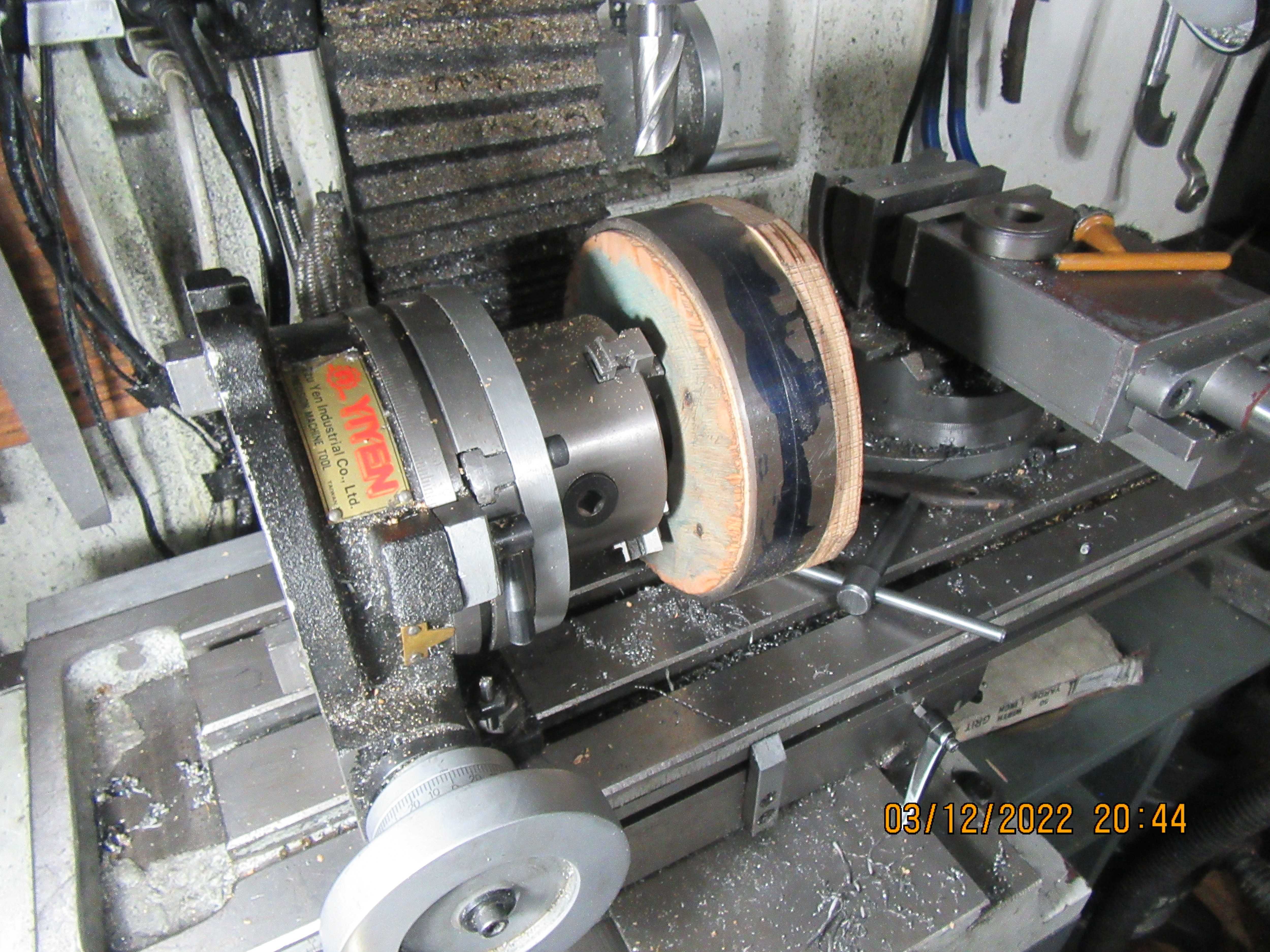
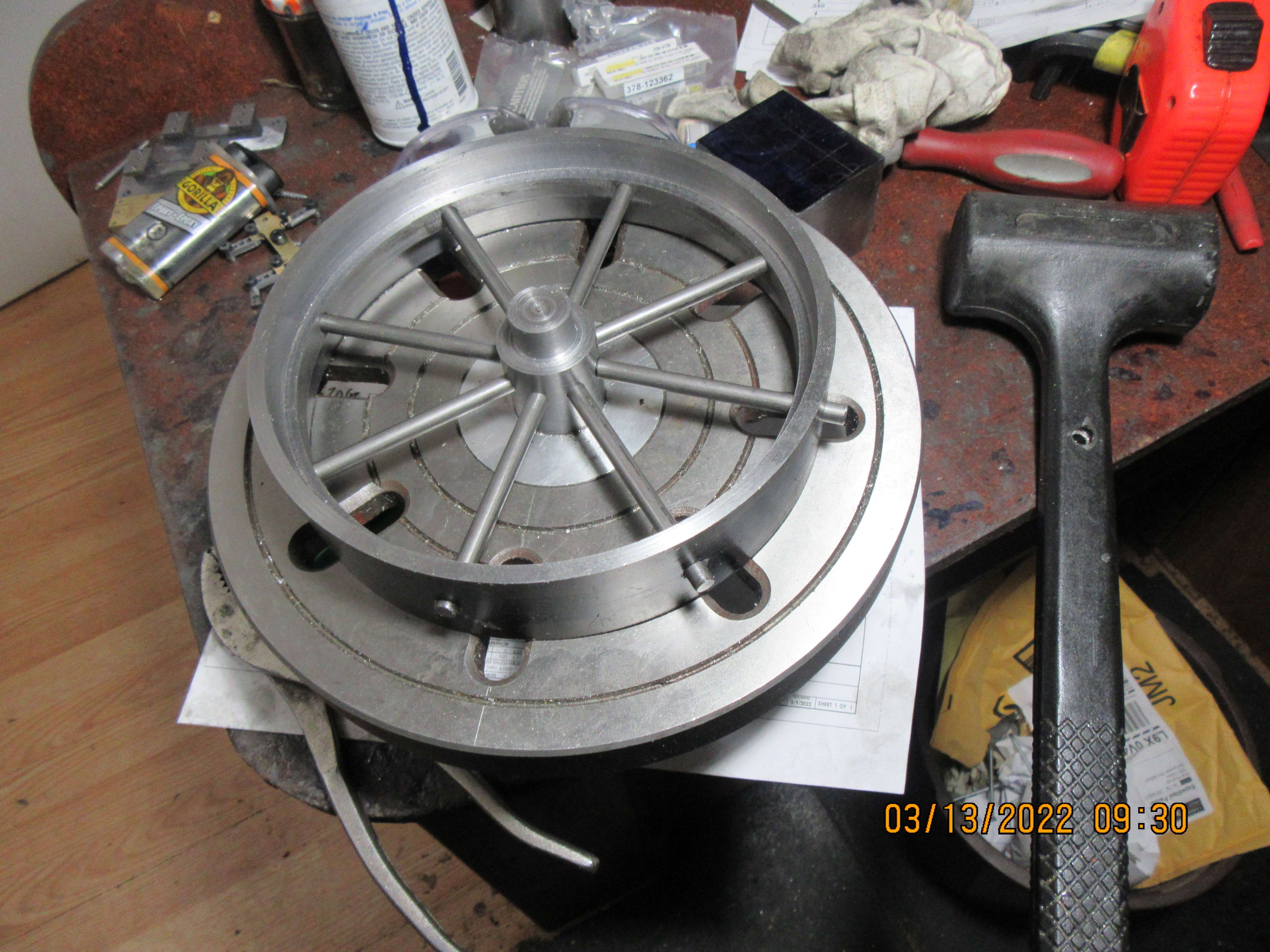
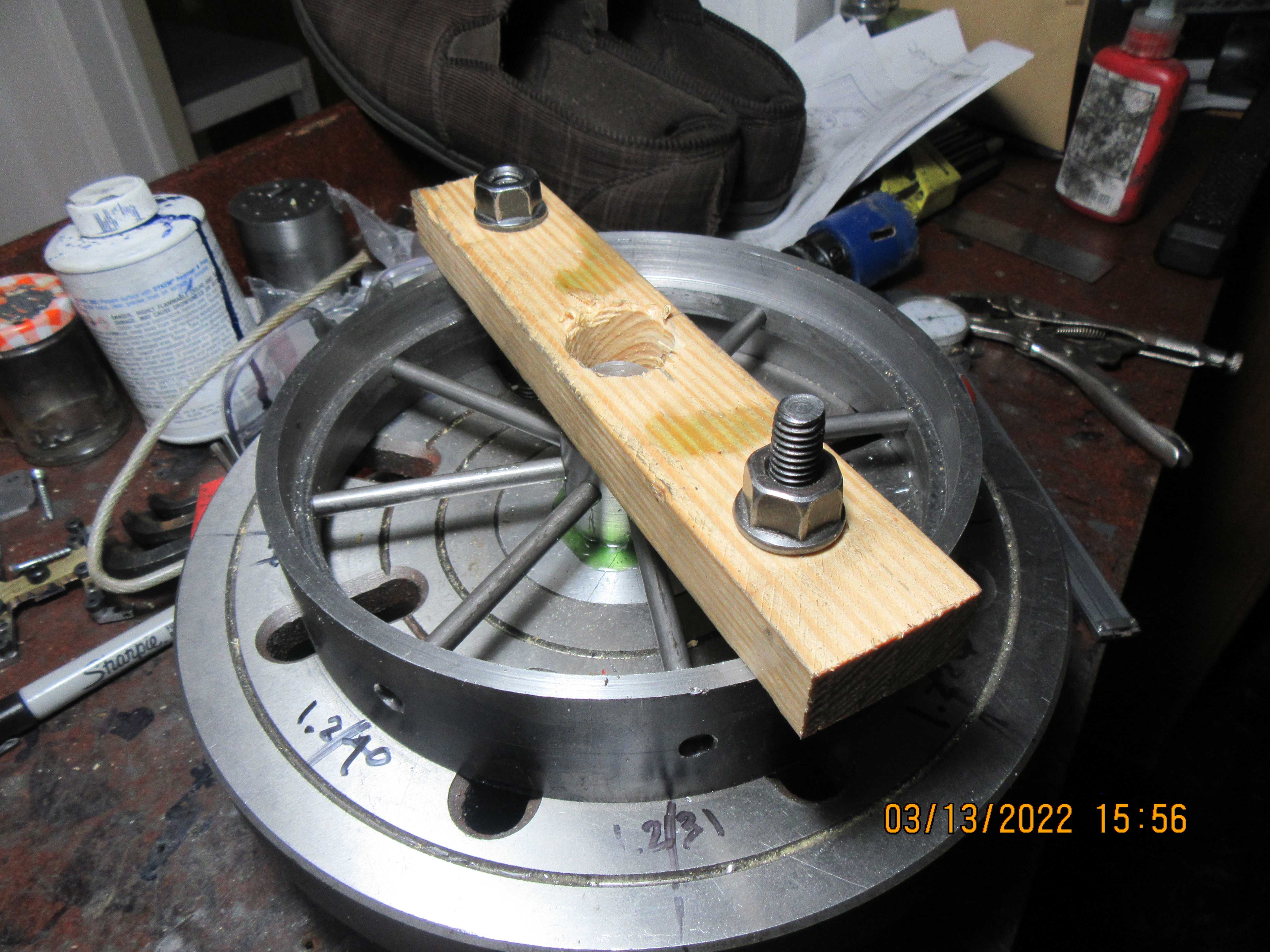
I've went "Full Hillbilly" on the set up to drill the outer rim of the flywheel. Thanks to Charles Lamont of the U.K. for the idea. A piece of 3/4" plywood was turned to be a snug fit into the counterbore on one side of the flywheel rim. The plywood has a 3" hole cut in its center and is gripped by expanding the jaws of the chuck on the rotary table. A second piece of 3/4" plywood is attached from the other side with long screw-nails to hold the steel rim so it doesn't fall off while being drilled. There is a centerline scribed on the outer diameter of the rim. Even if the outer diameter and the hole in the plywood aren't perfectly concentric, it doesn't matter. What I'm after here is the correct number of degrees between holes drilled in the rim. As long as I pick up the centerline marked on the outer rim every 45 degrees, the holes will be in the right place, even if the plywood "orbits" a bit when I advance the rotary table. The holes in the hub are reamed for an exact fit of the 1/4" spokes, because I am using loctite between the spokes and the hub. The holes in the outer rim will be drilled 1/4" and not reamed. This gives me a better chance of getting the spokes exactly in place, and since they will be welded to the outer rim I can afford a bit more clearance for fit-up.