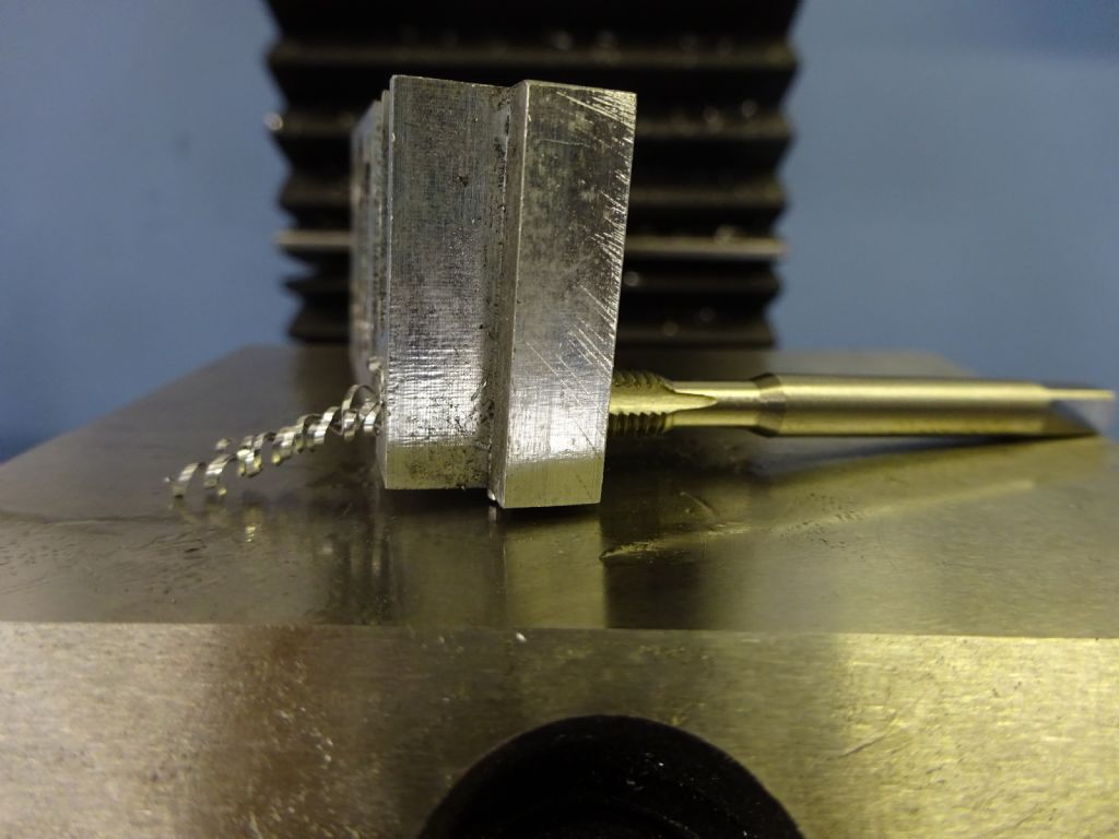
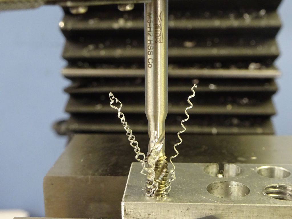
I do nearly all tapping in a stand I made decades ago to the George Thomas design


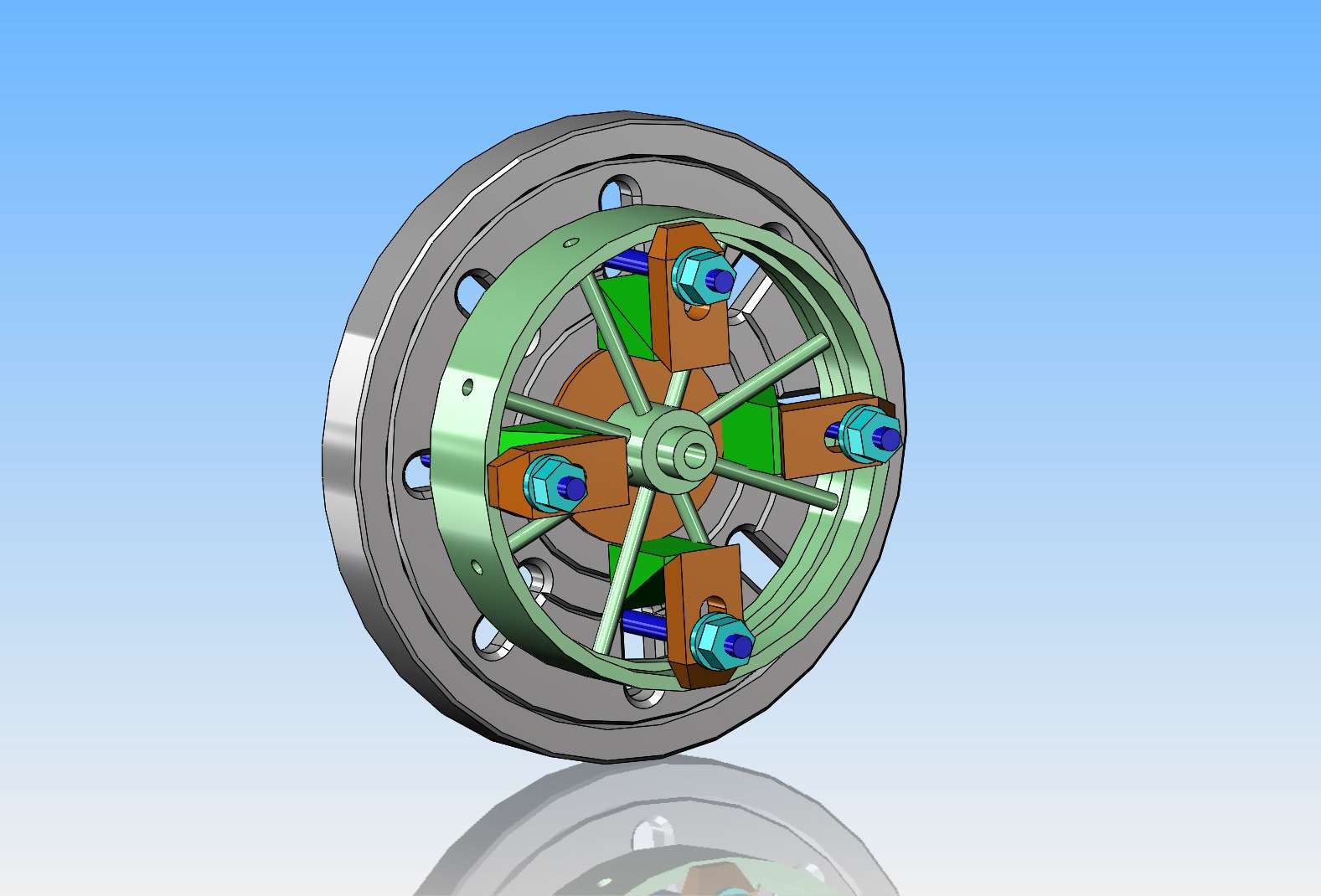
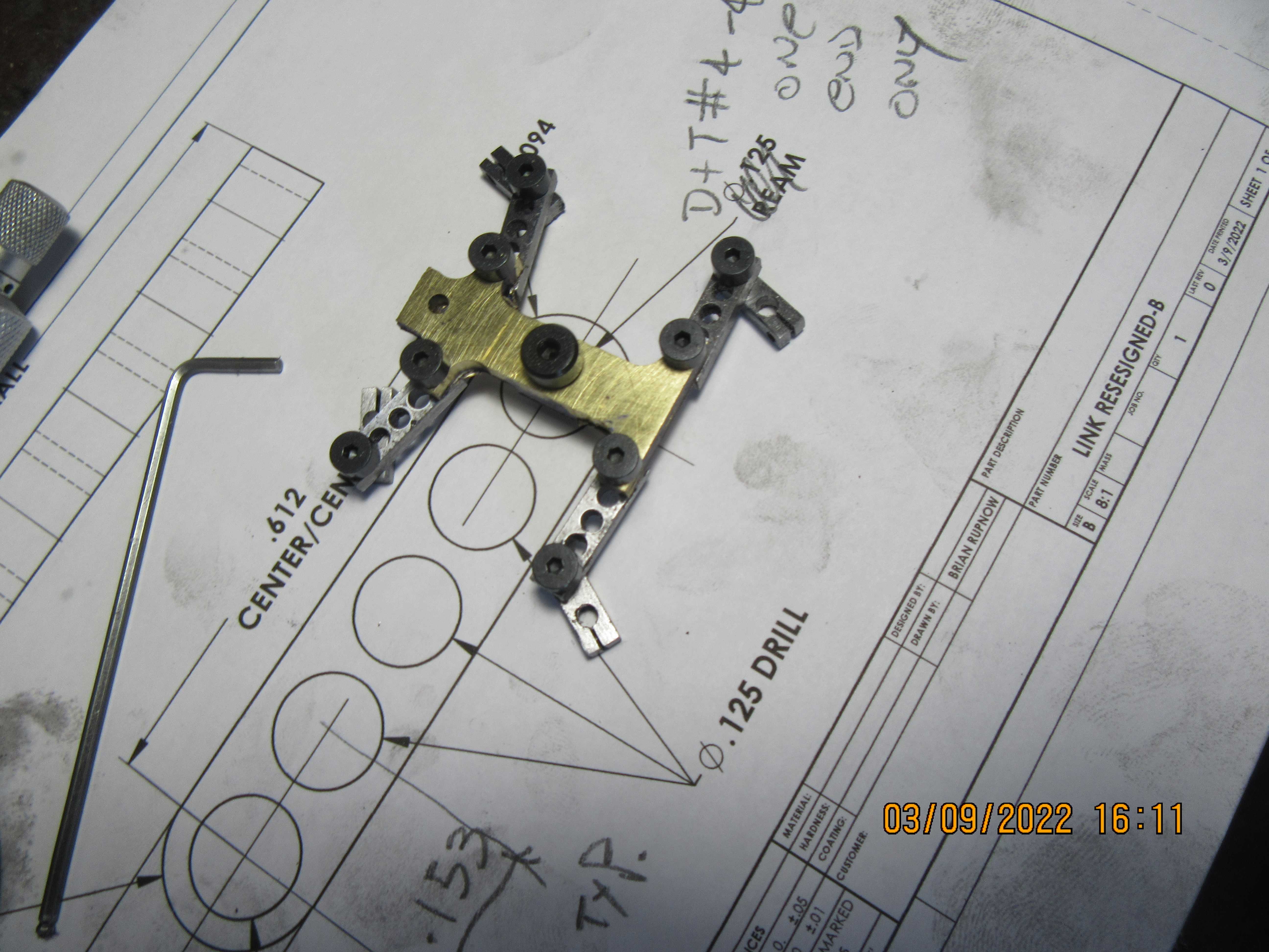


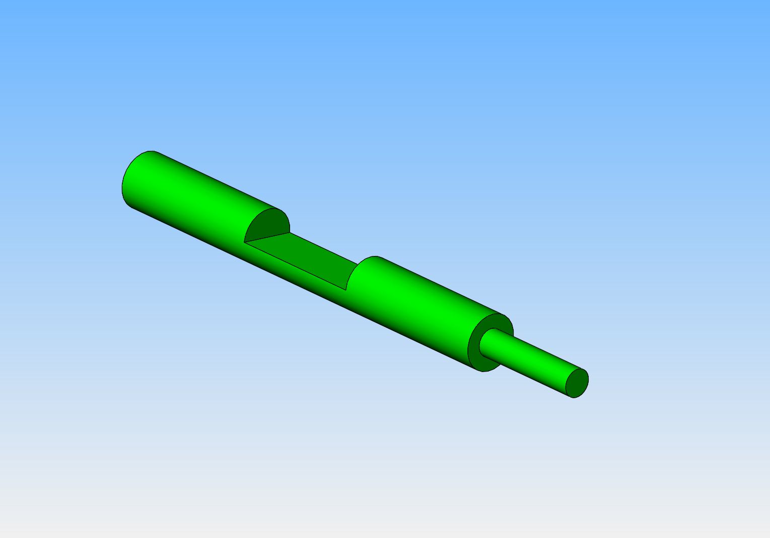
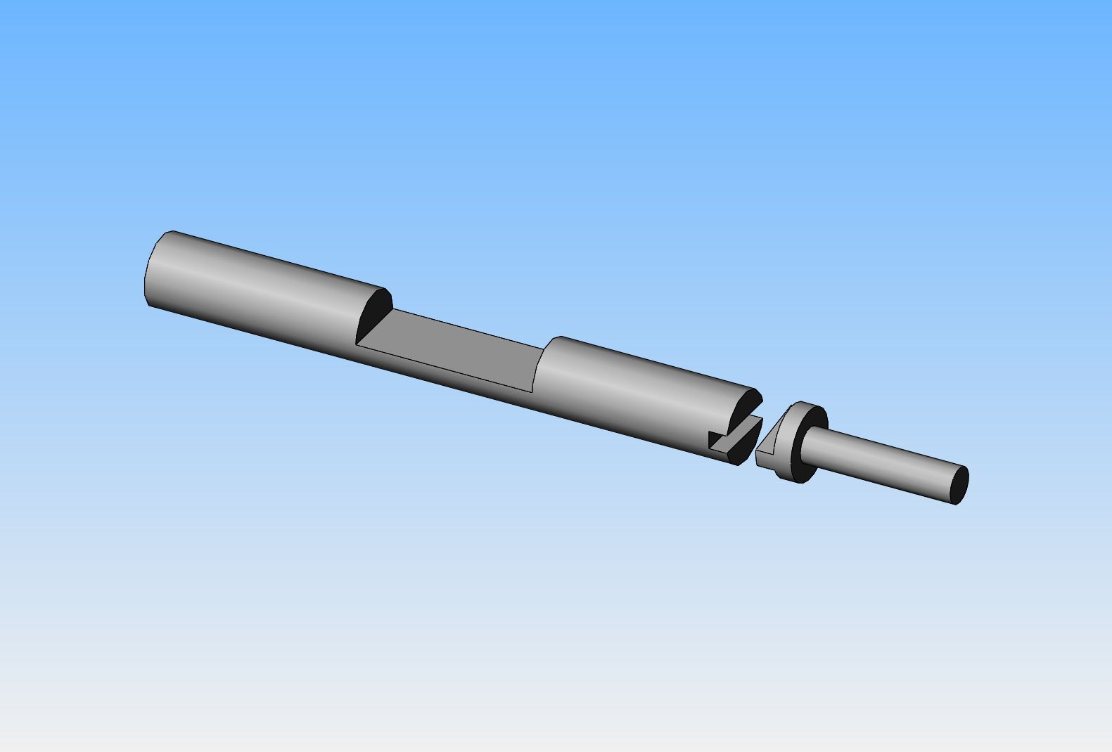
Question for anyone who may have built this engine. The 3D model I downloaded has the valve shafts in two separate pieces keyed together with a mechanical tongue and groove. Why is this so? Why not combine those two separate pieces and make them a one piece unit?
Brian, I omitted the tongue and groove on mine, and made a one piece brass shaft. It seemed to work well.
Enter your email address to join:
