


Well, you've got to start somewhere so this is my first engine build, simply called 'BME' which stands for 'Big Mill Engine'. .....pretty imaginative name hey!
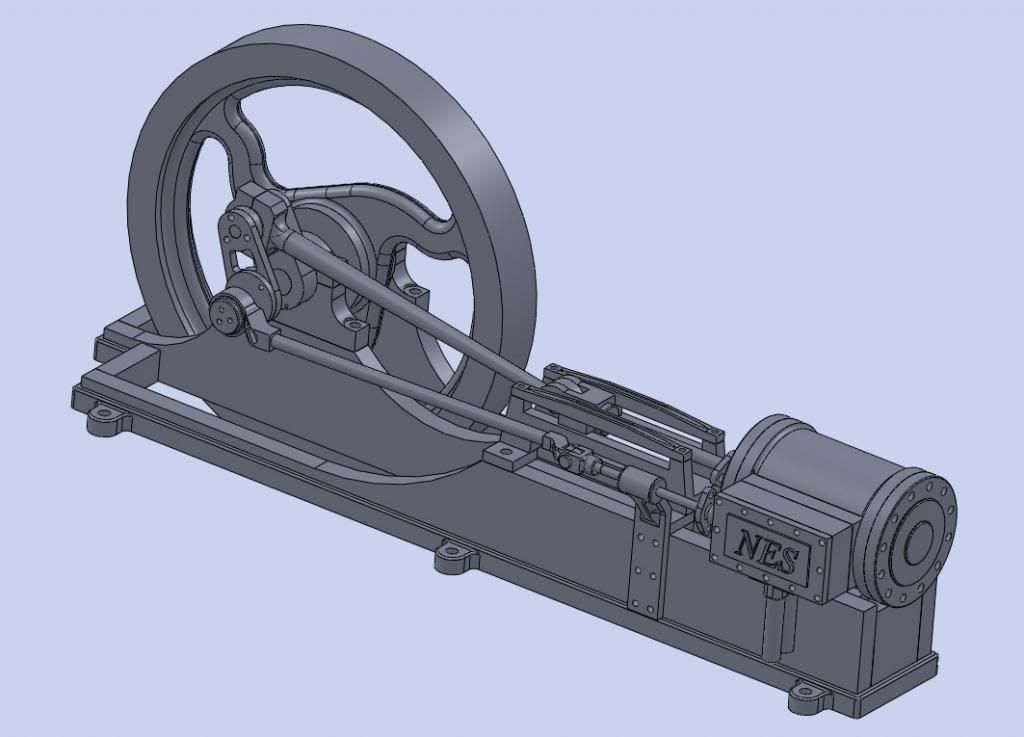
BME is my own design but obviously it is based upon the large, horizontal, single cylinder, steam driven, mill engines of yesteryear. In the design, I have chosen not to follow tried and traditional design rules that were characteristic of these old steam engines. Instead, I have gone with what is simple for me to make or whatever took my fancy during the design phase. (.....its also called taking the easy way out!) For example, I am using ball bearings throughout on all rotating parts and high lubricity polymer bushes on items such as linkages and the valve operating rod.
I have also chosen not to use the tried and tested eccentric to drive the valve mechanism. Instead, I will be using a crank which is driven by the crankshaft 'big end'. This will incorporate a plate that can be rotated through + or - 120 deg (when engine is stationary) which will enable the engine to be operated in a reverse direction.
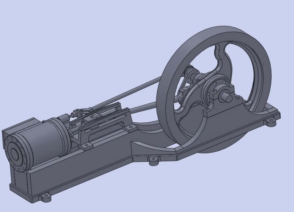
The entire construction will either be fabricated/welded or machined from solid stock materials. No castings will be used. All fasteners will be hex head, probably stainless. Fasteners are not shown on the two CAD views, ....my CAD toolbox is having a dummy spit at the moment! The design is 99% completed but I have yet to produce all of the 2D working drawings in order for me to build the engine.
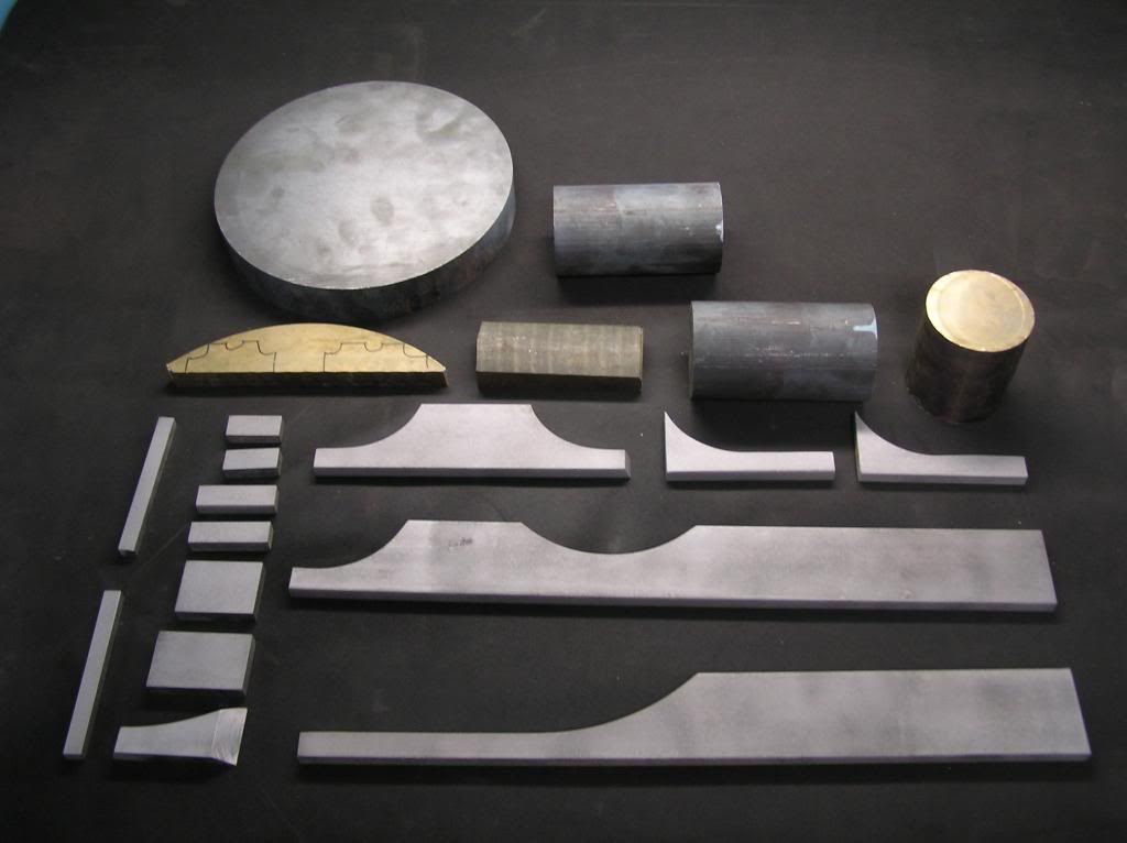
Basic dimensions are 440mm long, 40mm bore, 60mm stroke and 200mm dia flywheel. Materials are numerous, ...cast iron flywheel, cylinder, valve chest and cross head framework. Bronze cylinder end covers, valve cover, crosshead slider, main bearing pedistals and a few other parts, stainless steel crankshaft, crank throw, connecting rod, piston rod, piston, valve rod, valve connecting rod and valve cam parts. The chassis is built from 50 x 10 mild steel flat bar.
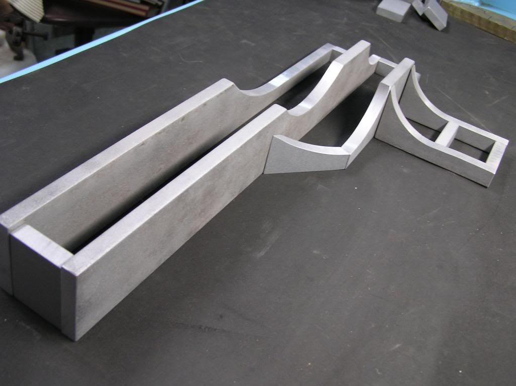
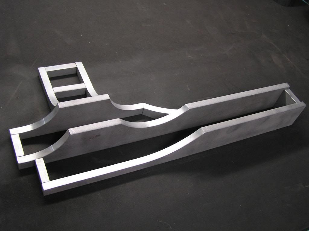
Current progress is that most of the materials have been sourced. The chassis parts have been cut, profiled, sand blasted and machined where necessary to fit together squarely. (using power saw, band saw, linisher, sand blaster and milling machine) The chassis has now been tacked together and then fully welded along all accessible joints by TIG welding. TIG was used in preference to MIG, stick, brazing or silver-soldering due to it's low heat input and controllable, small weld puddle, giving a neater joint. .....plus, I like using my TIG!
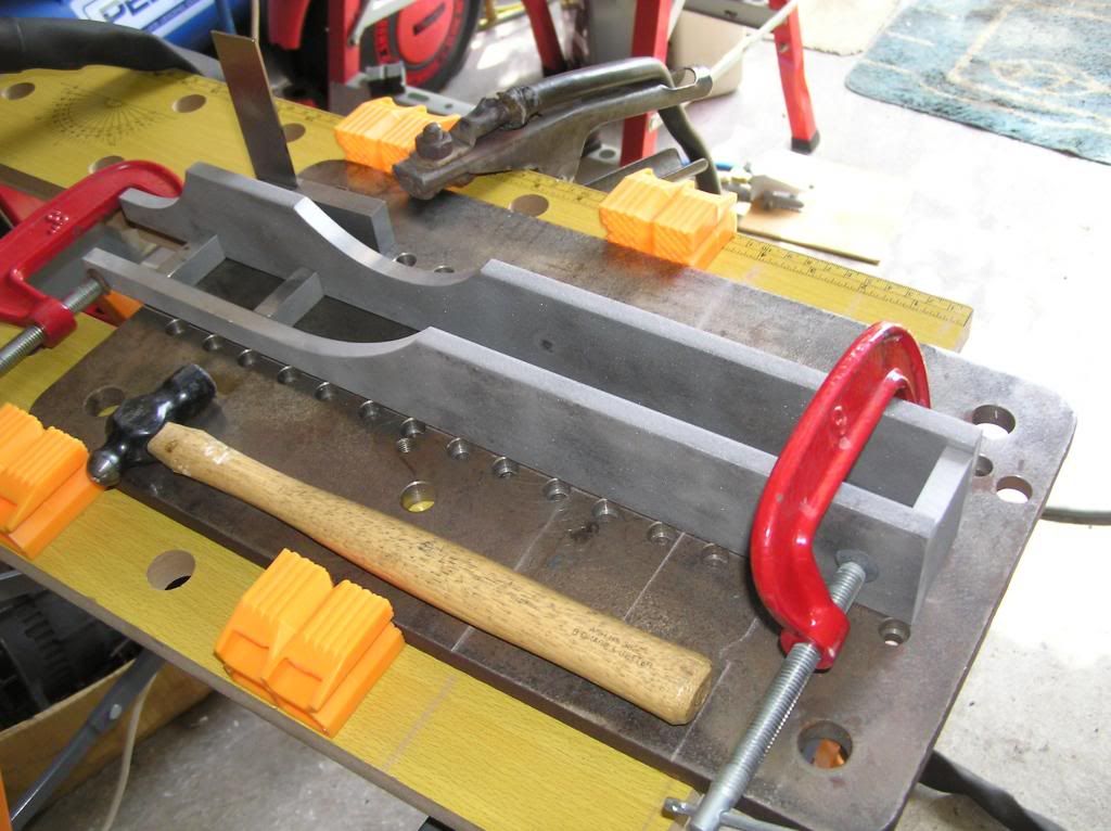
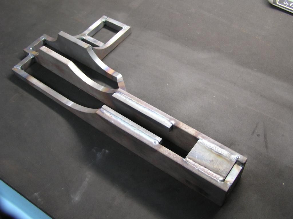
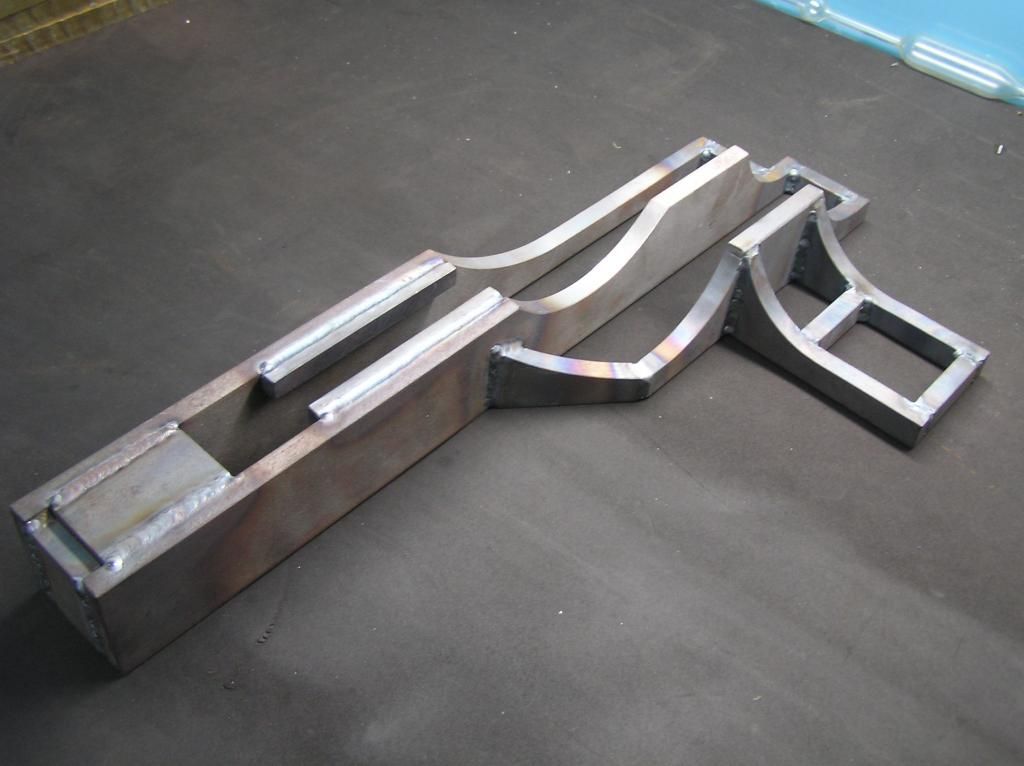
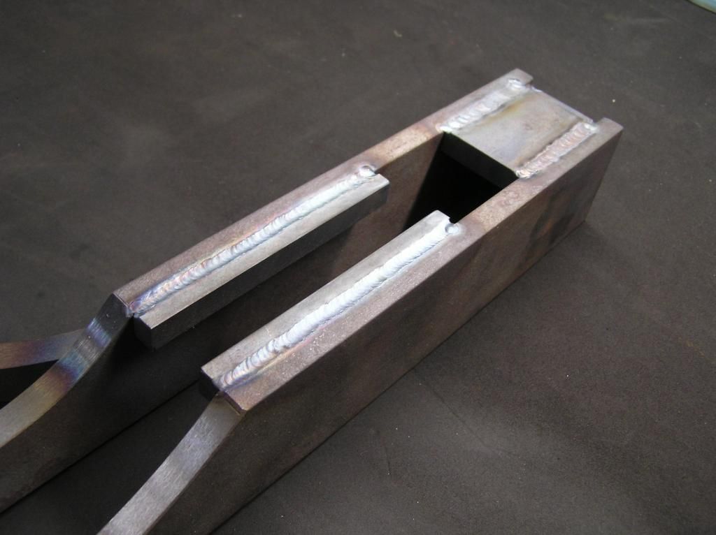
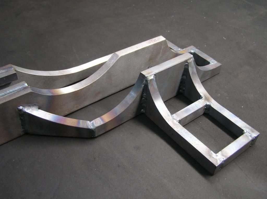
There is still a lot to do on the chassis including welding on about 8 bolt-through feet and possibly welding some flat strip around the base for featuring. It will then require some serious fettling and rounding off of all sharp corners and filleting of welds before I start any machining of it.
This is the progress so far and I will update as I go along.
Thanks for looking, Cheers, Norman.
BME is my own design but obviously it is based upon the large, horizontal, single cylinder, steam driven, mill engines of yesteryear. In the design, I have chosen not to follow tried and traditional design rules that were characteristic of these old steam engines. Instead, I have gone with what is simple for me to make or whatever took my fancy during the design phase. (.....its also called taking the easy way out!) For example, I am using ball bearings throughout on all rotating parts and high lubricity polymer bushes on items such as linkages and the valve operating rod.
I have also chosen not to use the tried and tested eccentric to drive the valve mechanism. Instead, I will be using a crank which is driven by the crankshaft 'big end'. This will incorporate a plate that can be rotated through + or - 120 deg (when engine is stationary) which will enable the engine to be operated in a reverse direction.
The entire construction will either be fabricated/welded or machined from solid stock materials. No castings will be used. All fasteners will be hex head, probably stainless. Fasteners are not shown on the two CAD views, ....my CAD toolbox is having a dummy spit at the moment! The design is 99% completed but I have yet to produce all of the 2D working drawings in order for me to build the engine.
Basic dimensions are 440mm long, 40mm bore, 60mm stroke and 200mm dia flywheel. Materials are numerous, ...cast iron flywheel, cylinder, valve chest and cross head framework. Bronze cylinder end covers, valve cover, crosshead slider, main bearing pedistals and a few other parts, stainless steel crankshaft, crank throw, connecting rod, piston rod, piston, valve rod, valve connecting rod and valve cam parts. The chassis is built from 50 x 10 mild steel flat bar.
Current progress is that most of the materials have been sourced. The chassis parts have been cut, profiled, sand blasted and machined where necessary to fit together squarely. (using power saw, band saw, linisher, sand blaster and milling machine) The chassis has now been tacked together and then fully welded along all accessible joints by TIG welding. TIG was used in preference to MIG, stick, brazing or silver-soldering due to it's low heat input and controllable, small weld puddle, giving a neater joint. .....plus, I like using my TIG!
There is still a lot to do on the chassis including welding on about 8 bolt-through feet and possibly welding some flat strip around the base for featuring. It will then require some serious fettling and rounding off of all sharp corners and filleting of welds before I start any machining of it.
This is the progress so far and I will update as I go along.
Thanks for looking, Cheers, Norman.
