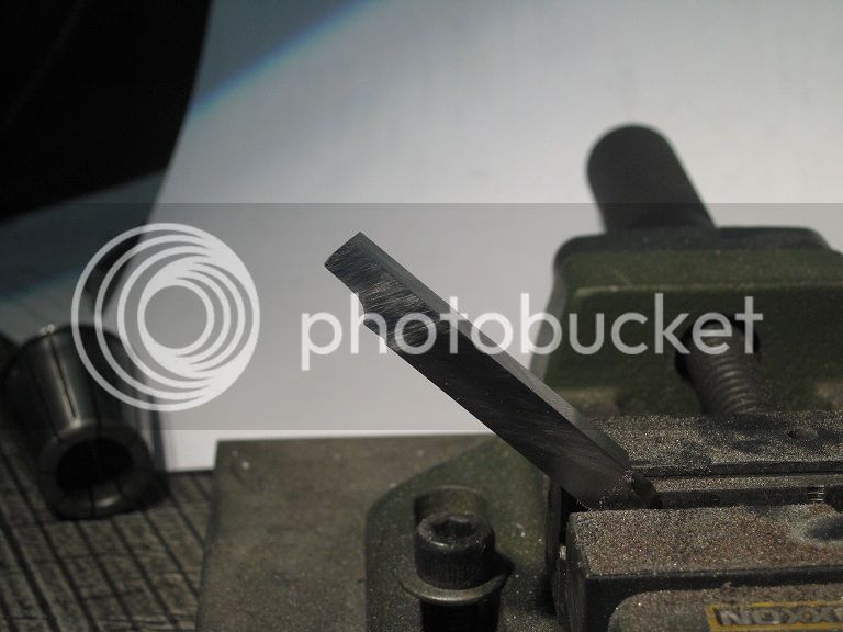
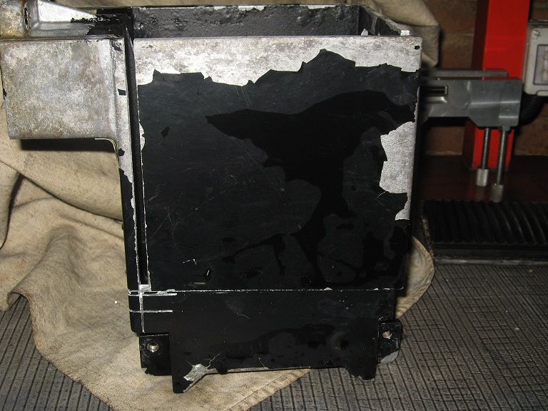
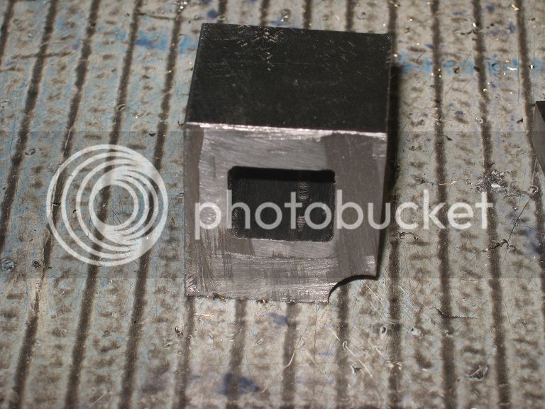
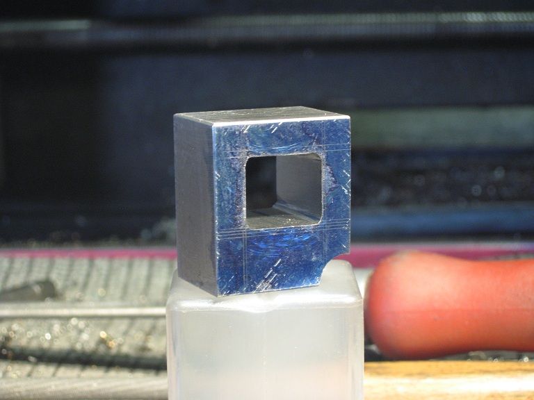
Bernay build - MZT

Home Model Engine Machinist Forum

Help Support Home Model Engine Machinist Forum:

This site may earn a commission from merchant affiliate links, including eBay, Amazon, and others.

Al. Conn. Rods


Here’s the blank, not quality aluminium, but the plate should do for the job.
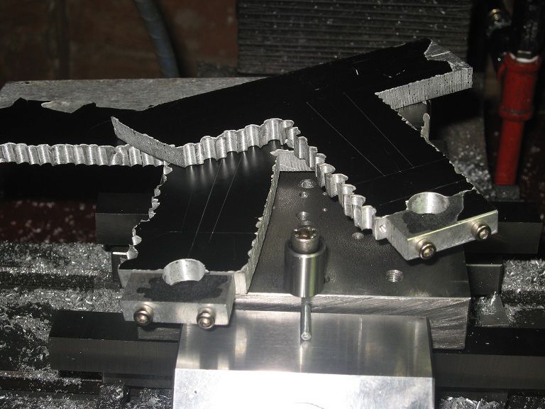
44_IMG_0789.jpg


Chain drilled

44_IMG_0792.jpg


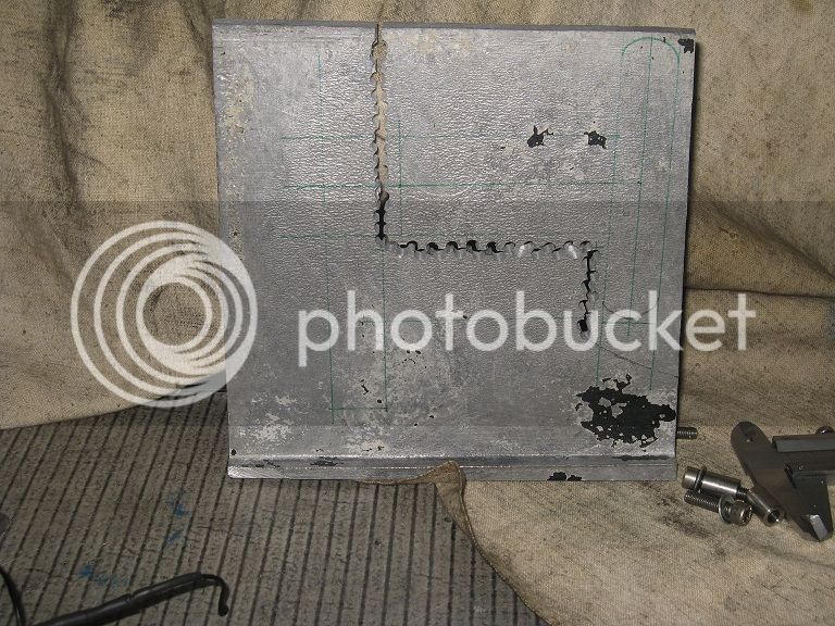
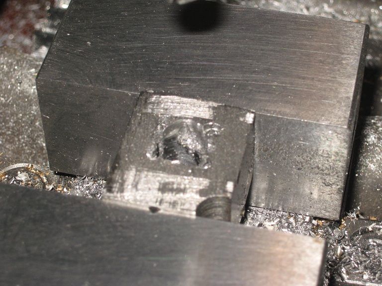
Using the vice as it were an angle plate
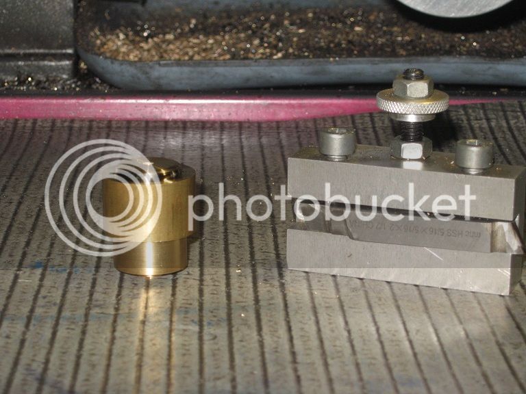
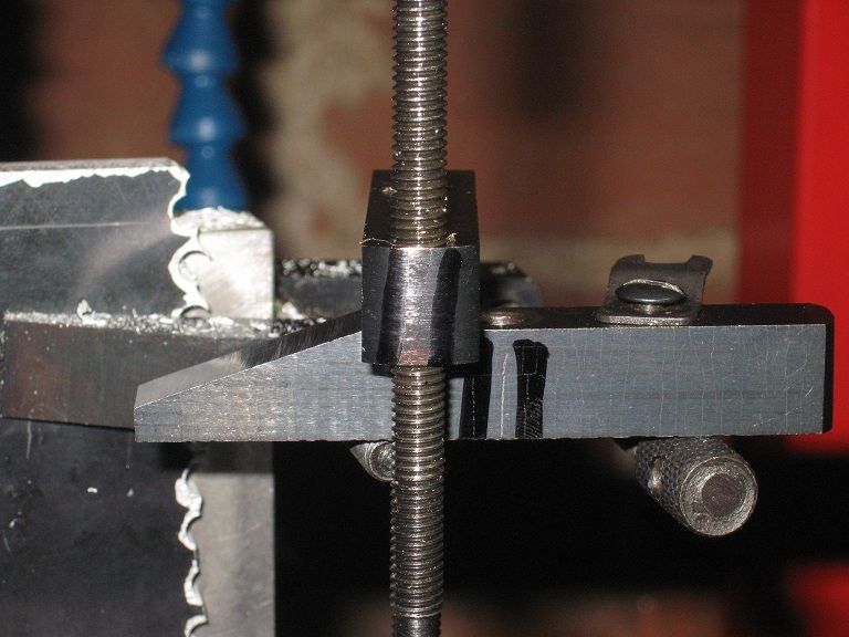
44_IMG_0798.jpg


Overtightening a toolmaker’s clamp: cracks among the marker lines.

44_IMG_0803.jpg


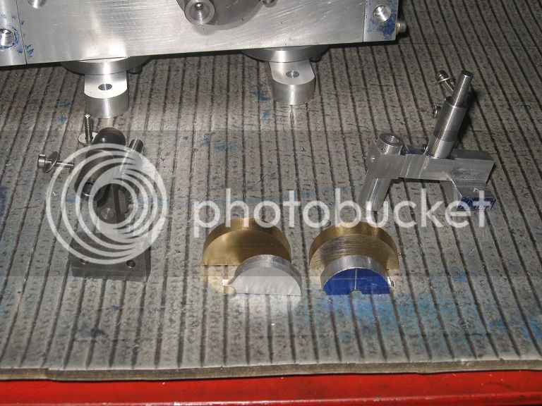
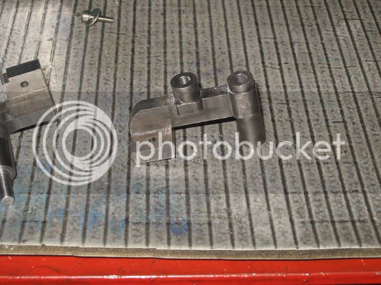
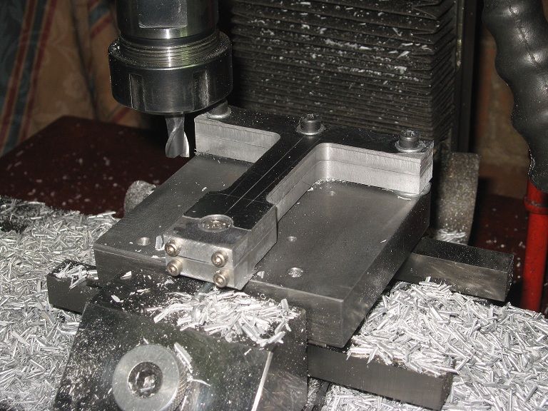
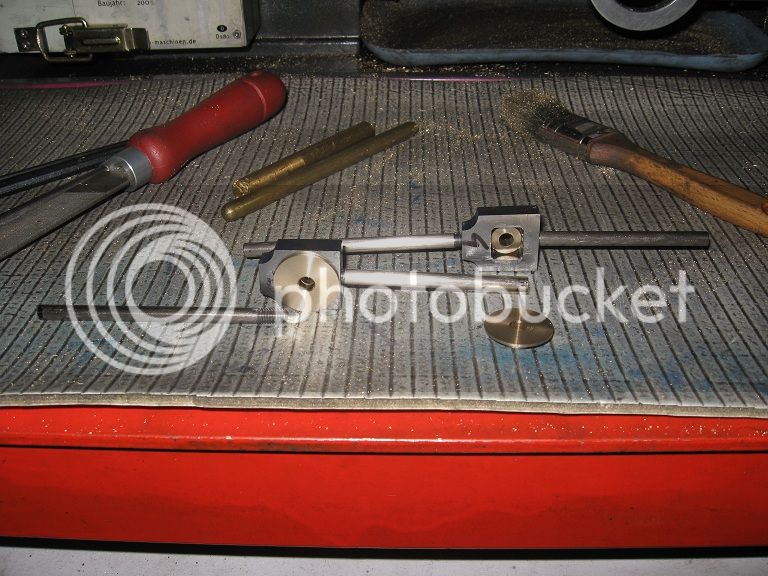
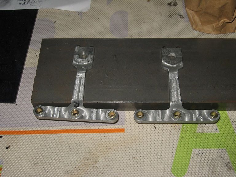
Bearing areas completed.

44_IMG_0806.jpg


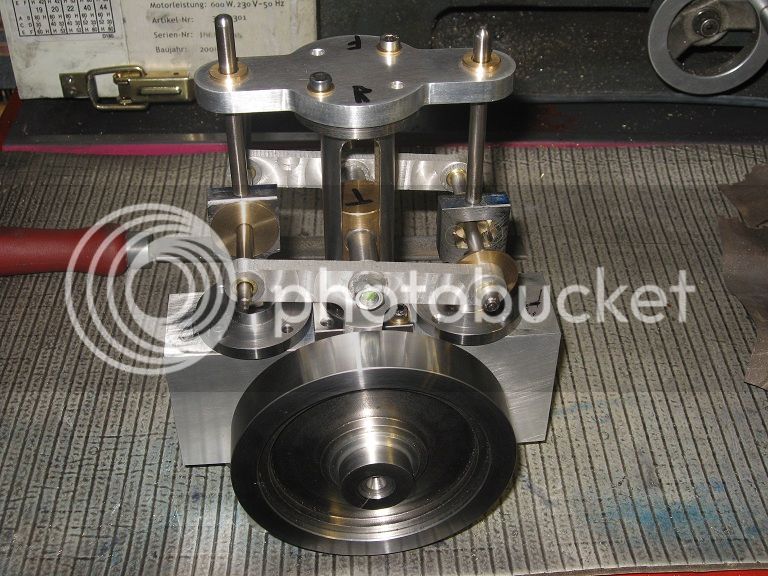
On the holding plate I had made before. A strip of paper (half circle) between the bearing feet
and the rod secured a firm hold without affecting the distance among the centers.

44_IMG_0809.jpg


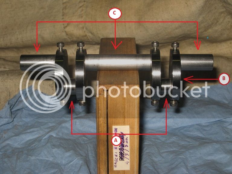
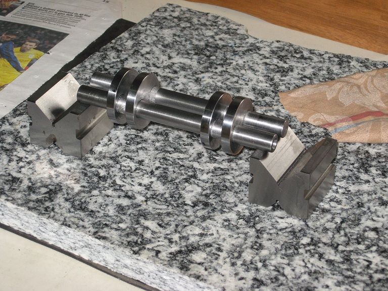
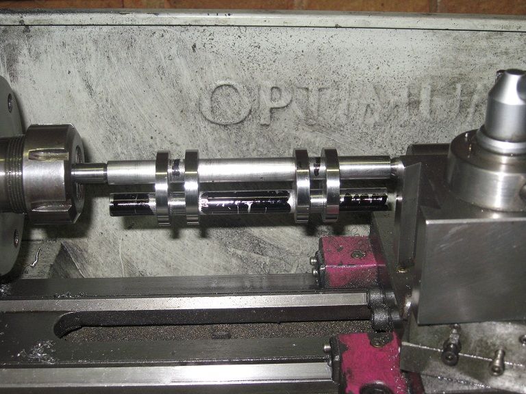
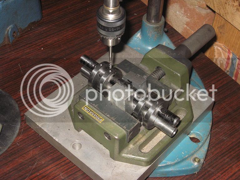
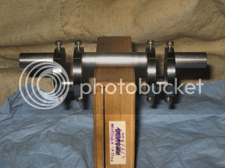
Constructed crankshaft (continued)


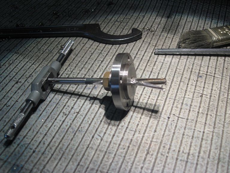
Chamfering the holes, using a wood board as support: the tool would surely grab the hard material (it did),
sharp edges, … : rather keep fingers far from that area.

44_IMG_0815.jpg


A quick test into hand reaming the 11.5mm holes to 12H7 convinced me to chuck an old 12.06 machine reamer
from the ‘purchased by weight’ bag.
Back on the holding plate, I screwed in a rod end I had turned to 11.5mm (added a clamp) and reamed one
hole in each of the four throws. Then, replaced the rod end with a 12mm one, and reamed the remaining holes.

44_IMG_0816.jpg


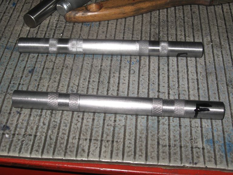
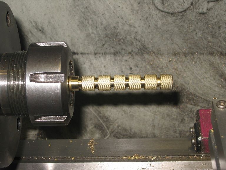
12.06 holes and 11.98 silver steel shafts in need for a press fit joint: solution came throgh knurlink.
Had ideas that straight knurlling would have been the way to go, but the wheels could not stand the work
on silver steel long enough. Had to revert to diamond knurling to complete the job.

44_IMG_0818.jpg


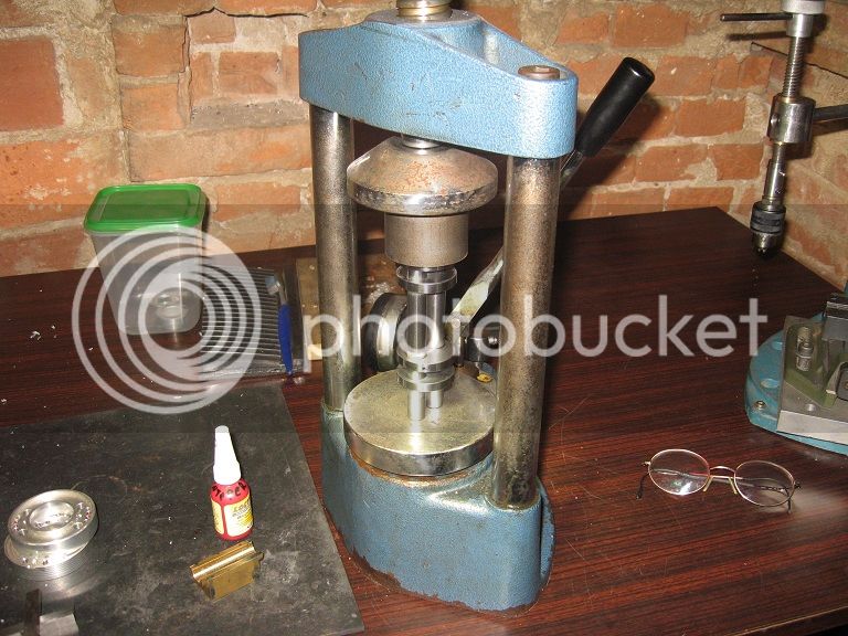
A bit of loctite (permanent thread locker - what I had) may do. Or may not, who knows.

44_IMG_0821.jpg


Testing for alignment: no point! I had reduced the ends in one of the two shafts (the ones I will cut!) to
whatever diameter they came, after having used them as test workpieces to try the knurls. Now it rocks,
but that’s obvious.

44_IMG_0824.jpg


A visual test spinning on the lathe showed no visible wobbles, and that’s the point I put it aside waiting for curing.

44_IMG_0826.jpg


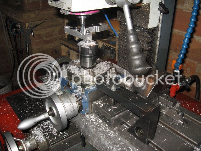
Al. Conn. Rods(continued)


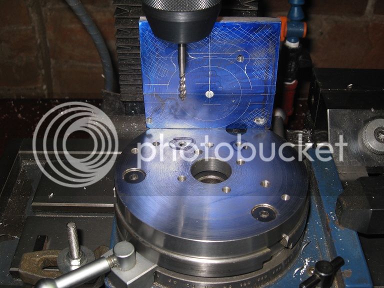
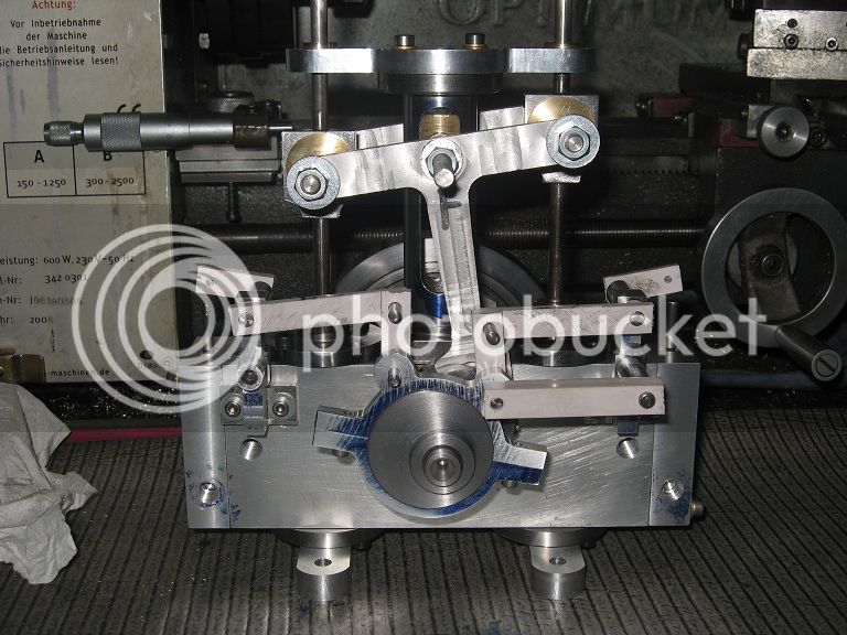
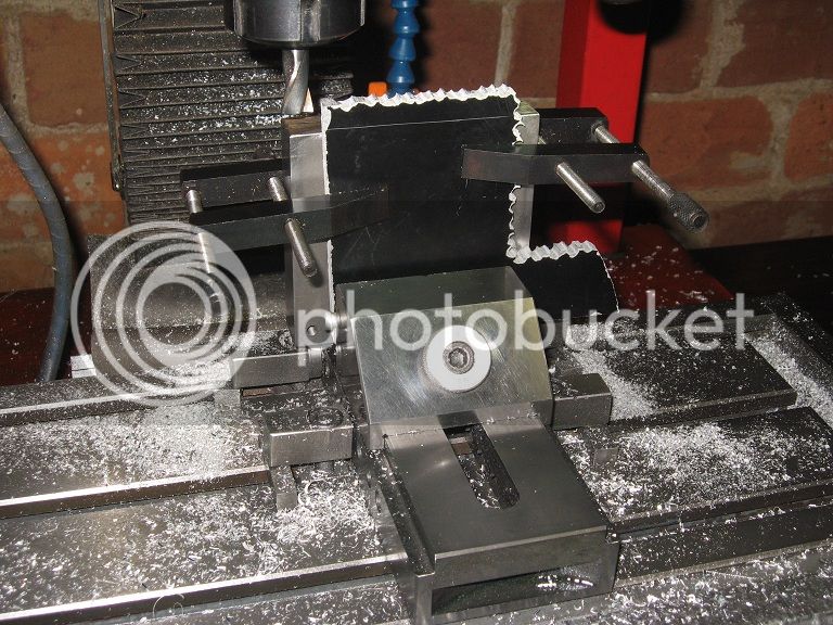
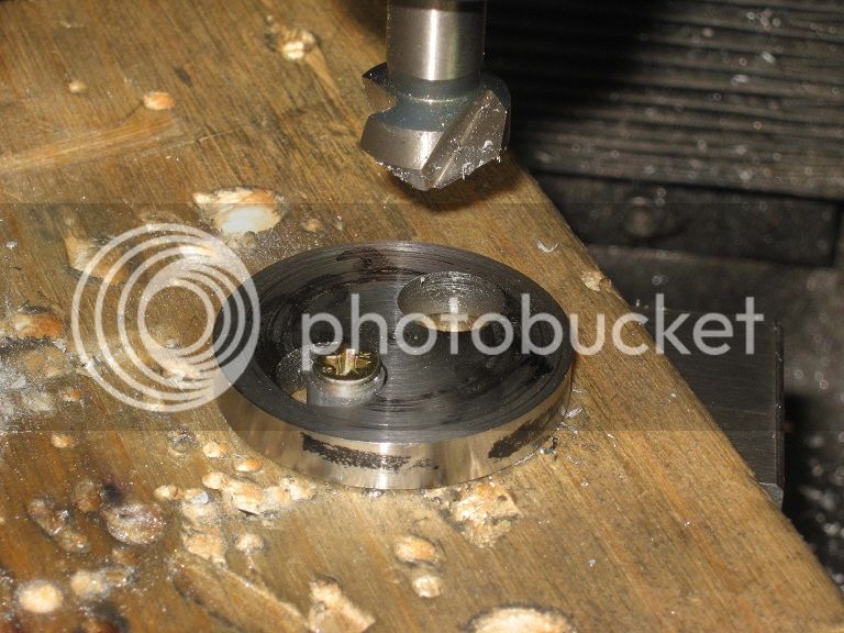
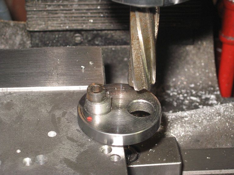
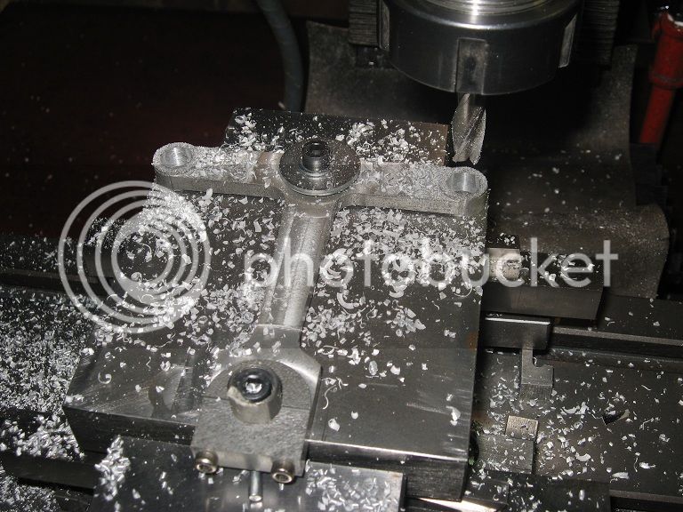
On the rotary table, to round the ends of the bearing areas.
The single-screw hold worked better than expected: I had only one slip, when milling to full depth the arcs
around the bearing area.

44_IMG_0832.jpg


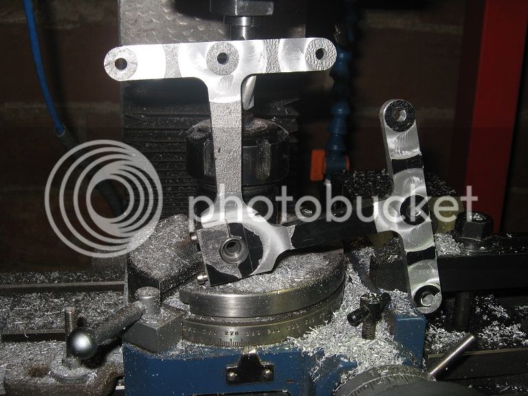
Rounding completed on both sides, end of workshop time. Will get back to them for finishing.

44_IMG_0835.jpg


Marcello


Constructed crankshaft (finishing)

Decided to drill eight holes for some screws going from the webs to the bearing sections: not sure they’re gonna add any strength to the assembly,
but they should prevent the parts from chasing the spectators, should it fall into pieces during the five minutes working life this engine is
going to expect (providing it will run).

I’d have rather used some 1/8” tapered pins, but in all the years I’ve had them in the box I’ve never got around making the appropriate D-bit:
I’ve ever postponed the job “to the moment I will need to use them” and tonite..
Well, I’m definitely not interested into grinding tapers.

45_IMG_0837.jpg


Some hacksaw work (and a lot of file work) later, I could spin the thingy into the lathe, for a visual check of eventual runouts: nothing I
could notice or “feel” by applying a wood bar to the far end. Had ideas about bringing the DI into play. It was late (reads: didn’t want to
spoil the satisfaction), maybe tomorrow.

Put a dab of permanent thread locker into each hole, instead, and here it is with the screws I will later cut and file flush with the cheeks.

45_IMG_0843.jpg


Marcello
 

Piston-rods

The printer bar material was a little too tight into the packing nuts, decided to try to get some clearance by interposing
a strip of paper between the reamer and the bore. It worked.

46_IMG_0847.jpg


Chain drilling a block of scrap to remove the bulk of metal before milling the rectangular pocket for the inserts and then
a big 10mm hole in the middle of the area.

46_IMG_0848.jpg


Took a file, then. And it wasn’t a quick job.
The rectangular hole came out all but rectangular, centered and with parallel faces.

46_IMG_0852.jpg


Put it back into the mill, the: faced the roughly cut surface as it can be seen into the previous picture, painted with
blue and scribed a few lines.
Back to vice & files, till I got this. It was fun.

46_IMG_0859.jpg


Piston rod inserts

They should be square, but I cannot see why they should not work if made round.

46_IMG_0869.jpg


Connecting rods

Tried enlarging a coupla bearing holes to the 6mm bearing size I needed (they were made 5mm dia. for mounting on the plate)
by hand drilling, but the idea was not good.
Rather make use of the plate again, to bring them to straightness and squareness again.
Took the occasion to remove some unwanted metal I had left on the body when I rounded the bearing areas on the rot-table.

46_IMG_0871.jpg


The connecting rods will have brass bearings.

46_IMG_0874.jpg


The knurling gave a push fit only, so I put a dab of loctite and set them aside for curing.

46_IMG_0876.jpg


Marcello


Alum. Bernay Taking shape


Had to solve a slight binding into the piston rods inserts, due to not enough side clearance into the rectangular slots : now I think of it,
I never cared checking their dimensions with the drawings while making them (…) ::)

A few strokes with a round file (green circles in the photo) and so much for my previous efforts into having them nicely finished. :big: :big:

A bit of work into cutting the rods to length, fitting the pistons, threading for the nuts, etc and here it is.


47_IMG_0879.jpg


Marcello
 
Looking the part Marcello! I'm a little confused with the crank...are you going to machine the journals now that it is all bonded together....?

Dave
:)
 
Dave,

now I'm confused (and worried) too!!!

Aint much sure about what parts You're referring to :(

CrankJournals_45_IMG_0843.jpg


(A) Should be the journals, (B) the throws and (C) I cannot name them at the moment, but I'm sure I've come across that term before.

Whatever..
(A)s are already to size as are (C)s, while (B)s should be rectangular as per drawings, but I liked the shiny finish I've got while turning them and decided to let them be round.
(If I wanted to make them as per drawing, I'd probably fit an alu. spacer among the cheeks, put them into the vice then a bit of handwork with framed blades and files).

So, answer is "nope, aint gonna machine another anything on that crank nor touch it in any way with tools".
Unless... ? ? ? ? ? ? Any bad news for me?

Marcello


Steam Chests


Yesterday I finally got around drilling and tapping the holes for the valve stems and steam intakes into the steam chests, wonder why I postponed this simple task so long.

Here’s a picture of the two of them, patiently (not sure about that!) waiting for me to make and fit the valves and linkages.

Quite a pleasant view on my lathe bench, You know the feeling I’m talking about.


48_IMG_0880.jpg


Now I think of the missing parts, the pipe fittings and steam covers are also still hidden somewhere into the metals pile. Then the wooden bases,
one eccentric strap, a hundred studs (if I decide to go for them in place of screws), some castle nuts, gaskets…

Still enough work to do not to feel hastened into having it done. ;D


Marcello
 

Another eccentric strap

Here’s the plates, already cut (and fastened) to the central line. I’ve centered the RT under the spindle, then fitted the support
plate and drilled four holes in it for the holding screws. Now, I will mill the bearing area to size, then cut the external shape
adding new clamps when the lower screws will cease supporting the workpiece.


49_IMG_0890.jpg


The task was completed successfully, the bearing having come out of the machine to a light fit with the eccentric.
In a few minutes of handwork, I got the sliding fit I was looking for.

Valve gear

Quite a few parts in it!
Started with cutting all the rods for the two engines to the length specified on the drawings and the diameter I had chosen when
making the parts. I’ve not been too consistent when converting the 0.185” measure to metric: sometimes it came out to 4mm and in
some other occasion it came to 5.
Bright side is IF I manage to make them correctly, then there will be little chances to mount the improperly.

Just to make myself sure about what I was going to do, I cut all the arms from a strip of plastics, drilled the holes at the
specified distances and press fitted (some light hammer blows) the rods into them.

Both engines accepted them without complains: the only item I had to make different is the one I could not find a drawing for,
though I’ve gone through the set a few times: that’s #1 arm, the direct link from the bearing to the support bracket. There’s a
slight difference of a few tenths of millimeter between them in the measurements I’ve taken on each engine, for aesthetical reasons.

49_IMG_0894.jpg


Though I has intentions of making them into metal as the next operation, I realized the press fitted arms on the brackets would have
got into the way bringing them to the desired level of completion. Rather do that job first and make the links later.

A quick look into the scrap box showed a few filing buttons of the shape I needed

49_IMG_0897.jpg


But not of the correct diameter.

In fact…

49_IMG_0899.jpg


I had to make them, but took no pictures neither of the buttons not the finished brackets.


Valve Rod gland nuts

Had ideas about making them through a form tool, here’s the results of my efforts with a Dremel on the second end of a 8mm lathe tool:
it cuts on the front and on the curved portion (the second notch being a relief for the end of the curve)

49_IMG_0902.jpg


Here’s how it cuts, a ‘facing’ cut on a test piece from the odds and ends. Of course, had I chosen the second end of a longer tool,
the setup would have been easier, but so it goes…
Not perfect, but the idea is not bad. Gotta work on it a little more.

49_IMG_0905.jpg


Not having enough length of 14mm hex bar to make the four nuts I needed, I made only two out of it, and got the other two by knurling
and doming some 13mm brass rod. Not that I had not thought about filing them from larger stock, but shop temperatures over 30C put
little interest into doing that. Rather drill and hacksaw the valve arms, instead.

Marcello
 

Latest posts

Back
Top