Bernay build - MZT

Home Model Engine Machinist Forum

Help Support Home Model Engine Machinist Forum:

This site may earn a commission from merchant affiliate links, including eBay, Amazon, and others.

mzetati

Well-Known Member
Joined
Dec 2, 2010
Messages
236
Reaction score
6
Hi HMEM,

at the moment, I've already made a good amount of work on the cylinders and 'published' it in four different (long, in time and number of pictures, if not in words) posts on the classicsteamengineering forum.
Now, it occurred to me that this build would 'belong' to this place, too.
'Old' posts will follow, then I will keep both sites updated on my progresses (and regresses).

Marcello
 
The Cylinder Block

Wish I could find a suitable piece of cast-iron for it: cast-iron, here, being harder to find than pure unobtanium.. ..unless You’re willing to buy complete bars, 6 meters long.
Started it from that huge block of aluminium: the first hacksaw cutting already made, two more awaiting.

01Cyl_IMG_1981.jpg


When I got the block to size, painted with the blue and scribed.. I realized I did not want to make it in al. exactly the way its described in the drawings: the block is now I/4” oversize.

01Cyl_IMG_2035.jpg


Long time (and a slitting saw, which literally exploded: USE PROTECTIONS!) later, the block is again “to size”, painted with the blue and scribed.

01Cyl_IMG_2038.jpg


Drilling the hole for the crankshaft: that 18mm bit does not see much use.

01Cyl_IMG_2039.jpg


And boring to size (didn’ t like the look of the carbide tipped boring bars I had, especially on al. It was just a matter of a few minutes at the bench grinder to gain that HSS one).

01Cyl_IMG_2040.jpg


Now it occurred to me that I could probably have gained better results in less time if I had taken a different path:
1) Drilled that hole, say 19mm.
2) Inserted a press fitted bronze rod
3) Milled the slot in the top face till I reached the horz. diameter of the rod.
4) Inserted a rectangular bronze substitute
5) Bored the two parts rod ‘crank size’ on the parting line (a V groove in each of them, to duide the drill would have helped).
6) Set on the faceplate to face one side & make the boss.
7) Reversed on the faceplate to face the back

A picture might help:

01Cyl_ZDrawing.jpg


Too late.


The Bronze Bearing
Here’s the blank, and an aluminium plug, turned to size, to be used to compare the final diameter of the bearing, fitted into the block.

02_BB_IMG_2122.jpg


Reducing one end to less than 20mm (maximum collet size)
02_BB_IMG_2124.jpg


Turned oversize, and drilled undersized.
02_BB_IMG_2127.jpg


Now, on a V-block for scribing the parting line on the maximum diameter.
02_BB_IMG_2130.jpg


Hacksawed, after spending a fair amount of time into smoothing the surfaces (sandpaper)
02_BB_IMG_2131.jpg


The 2 parts were loctited , clamped and left curing: here’s the egg-shaped item I got after removing the clamps.
02_BB_IMG_2136.jpg


Centered (as much as I could center an egg) in the 4jaws, to turn the ‘collet portion’ round, again.
I did not want to take the risk of seeing the two parts splitting during the cuts, hence the iron wires on the bearing body.
02_BB_IMG_2138.jpg


Into a collet, again. Had to use a mill (for rigidity) to straighten the crankshaft hole end make both ends round, once more.
02_BB_IMG_2144.jpg


Now machining a couple of aluminium rings, to be press fitted on both ends.
02_BB_IMG_2146.jpg


Under the press.
02_BB_IMG_2147.jpg


It’s now time to bore to crankshaft size, and the outside to fit the cyl. block.

02_BB_IMG_2149.jpg


Some more pictures were taken while finishing the bearing, but I do not have them handy at the moment, will add them later .

In the meanwhile a drawing would do. Green=shaft, brown+yellow = lower bearing. White = upper bear.... ...GRRRR!!!


02_BB_ZDrawing.jpg


I should have taken better care into centering the bearing on the parting line, I suppose.

Got a few ideas about eventually fixing that part, maybe making a new one (now I know how NOT to make it:).
By now I’ll be using it to complete the cylinder block, just to see whether the assembled parts would work.

 
The Bronze Bearing (continued)

Here’s the bearing on the lathe again, to turn the outside diameter to size and part off to length.

03_BB_IMG_2154.jpg


03_BB_IMG_2158.jpg


Done!

03_BB_IMG_2156.jpg


The Cylinder Block (again)

On the mill, to saw off the upper portion of the bearing area: two cuts right below the scribed lines, as thin and precise as I can get them.

04_Cyl_IMG_2160.jpg


Milling the sides of the slot to a smooth finish

04_Cyl_IMG_2179.jpg


At the moment of test-fitting the bearing into the cylinder, I discovered the fit was a little bit on the tight side, more than I wanted it to be: had to enlarge the space between the external flanges of a few hundredths (of mm).
Not a difficult job, just a matter of fitting another couple of rings on the ends, mounting the thinghy on a madrel and then again in the lathe between centers.
This time, the rings were a bit too tight: and the press did the rest. One more item for the future projects box.


--

The Cylinder block (take two)
Got fed up with that al. block!!! Starting over with a large chunk of bronze: the usual sequence of hacksaw works, then file, and mill to have it squared and to dimension. No pictures - I was too nervous -.
Now the block is ok to restart on the cylinder, without straying too much from the drawings , this time.
Yeah! But what shall I do with the other block? Spent a few days idling with some machine modifications while deciding what to do, then put the bronze back on the shelf.

--

The al. Cylinder block – a different approach

I milled a rectangular slot, and drilled 2 holes on its centreline, spaced 30mm, to be tapped M3

04_Cyl_IMG_IMG_2193.jpg


Drilled, and bored the cylinders

04_Cyl_IMG_IMG_2197.jpg


To “gauge” size

04_Cyl_IMG_IMG_2198.jpg


I had no doubts the drawings were for 1” dia. cylinders... ..re centered, re boring.... and an off-the-shelf gauge.

04_Cyl_IMG_IMG_2200.jpg


04_Cyl_IMG_IMG_2203.jpg


A view of the steam ports

04_Cyl_IMG_IMG_2205.jpg


Ready for milling/drilling the steam passages (31deg instead of 28.xx – playing a bit on the safe side, now -. :)

04_Cyl_IMG_IMG_2209.jpg


All done, but tapping.

04_Cyl_IMG_IMG_2214.jpg


The Brass Bearing

Drillied two 3mm through holes and two 1.6mm holes on the sides of the lower part, the two matching holes (dia 1.7) on the upper portion, then cut a groove 3mm wide 1.5mm deep on the centreline of both of them

05_BrB_IMG_2216.jpg


05_BrB_IMG_2217.jpg


Will put special care into centring the tool on the parting line when drilling for the crankshaft, I kno’ I must.

05_BrB_IMG_2221.jpg


05_BrB_IMG_2223.jpg


Marcello
 
The Brass Bearing (continued)
Two short portions of a of a blunt 1.7mm drill bit shank were tapered on one end and rounded on the other, then lightly hammered into the undersized holes in the lower portion of the bearing, to aid keeping things aligned during the subsequent operations.

I aligned the bearing into the vice, and started the crankshaft hole with a centring bit, to prevent the 4.5mm from grabbing and wandering into the square slot.

06_BrB_IMG_2234.jpg


It did not grab, but a check with a mirror showed the bit had gone through the workpiece all but straigthly… ..the square slot idea did not help much into preventing that. Next time I will try with a small V groove.
By now, I’ve gotta fix this one: I chucked a 7mm milling bit (the longest I have, in reasonable sizes) and carefully plunged it into the workpiece, taking advantage of the increased rigidity of the tool.

Another check with the mirror strip (graciously offered by a discarded laser printer) confirmed I was on the right way.

06_BrB_IMG_2238.jpg


The ‘next step’ with a blunt 10mm almost ruined the job… sounds like drilling is not an option, here: rather mount the boring head and go with it. Had a toolmakers clamp added to the setup, in the meanwhile.

06_BrB_IMG_2246.jpg


In slow steps to 11.8mm diameter.

06_BrB_IMG_2247.jpg


And ream to 12mm (I know drawings call for 1/2”, but aint got any stock in imperial sizes and do not yet know wheter the crankshaft will be cut from the solid or built up from barstock).

06_BrB_IMG_2250.jpg


A view of the reamed bearing fitting in place: still some lathe work is needed, to bring it to length together with tapering the ends. A test with the 12mm shank of a miiling bit showed I could easily insert it into the lower part, and fit the upper portion too!!

06_BrB_IMG_2253.jpg


Now on the lathe for the final steps: the chosen tool were the faceplate in combination with an angle plate (aint much happy with using my 4 jaws...).
I chucked a 12mm HSS blank into the (recently overhauled – now it is at the correct height!! -) TS as a reference for the workpiece bore, shimmed it (25/100mm)and aligned so it could turn over the blank with no tight points.
(That aluminium faceplate I made has no, and probably will never have, T-slots for adjusting the angle plate. At the moment I had little interest into drilling another hole closer to the centre to raise the angleplate a little more)

07_BrB_IMG_2256.jpg


1st side finished!

07_BrB_IMG_2257.jpg


Again, on aligning the bearing to machine the second side

07_BrB_IMG_2258.jpg


Testing the results on the cylinder block

07_BrB_IMG_2260.jpg


The bronze cylinder...
Tonight the shop radio was playing an old E,L&P LP “without interruptions”: did not want to mix the music with machining sounds, nor to spend my little shop time idling ...
..“whaddabout a lil’ scribing on that lump of bronze I had put back on the shelf some days ago, just for the fun of doing that?”

08_BCyl_IMG_2263.jpg


Obviously, answer was “yes! I will do some more shop work tomorrow!”


(P.S. Yesterday night they were playing the Doors...
... fortunately, I had a cupful of used carbide inserts from a real workshop trash bin to examine, divide by shape, type, size...
Gotta forget about that radio, if I want to cut some more metals on this project. : )

Marcello

 
Could not resist to that bronze block!
Here it is, sitting on the vise, being centered by ciggy paper & DRO.

09_BCyl_IMG_0001.jpg


No pictures were taken during the making of the cylinders : anyway, that was just ordinary drilling and a little ..boring.
Here, I’m roughing out the slot for the bearing, making use of a roughing mill: it cut like butter!

09_BCyl_IMG_0004.jpg


Finishing the slot with a 15mm end mill: wandering a little from the drawings, I stopped at 17.something millimetres, to make use of some bronze offcuts for the matching part.

09_BCyl_IMG_0007.jpg


Cutting a V groove into the lower portion of the bearing to aid the drill stay in line.

09_BCyl_IMG_0009.jpg


On the left, the top portion of the cylinder block I had hacksawed, and the already cut piece for the upper bearing.

09_BCyl_IMG_0016.jpg


I milled the upper bearing .05mm oversize, then toyed myself for a couple of hours with engineers blue, files, sandpaper and stuff to get a nice fit of the cover into the cylinder block.
In the end, I put a little grinding paste on the bottom to have a nice fit on the base, too.

09_BCyl_IMG_0018.jpg


After drilling 4 holes in a 1.02” square into a small plate from the scrap pile, I added another 6mm drill in a convenient position, for another wandering from the drawings.
Here, I’m tapping the four holes I’m gonna use next.
(While I was there, I tapped them all)

09_BCyl_IMG_0020.jpg


Eyespotting the 6mm hole, before drilling.

09_BCyl_IMG_0021.jpg


After drilling, and tapping.
Dunno whether is there any sense in that or not into that, but I do not want to have movements into those parts during the subsequent operations.
Sure, the punchmarks I had put on them to prevent reverse mountings are now redundant. :)

09_BCyl_IMG_0024.jpg


Flycutting the cylinder back, before drilling ...

09_BCyl_IMG_0044.jpg


..and reaming to 8mm

09_BCyl_IMG_0046.jpg


PS: the V groove worked like charm! I had no means of checking how the drill was going, having the large workpiece mounted low in the vice.
Got the bearing hole dead on center!
Time to go on the ....

...mill again.
I needed a 9mm hole, why did I ream it to 8???

Remounted on the vice, upside down for a change, re drilled and re-reamed.

09_BCyl_IMG_0047.jpg


Tapping the second end of the aligning jig for the faceplate

09_BCyl_IMG_0050.jpg


The faceplate, the dismounted jig

09_BCyl_IMG_0051a.jpg


And the jig in use

09_BCyl_IMG_0056.jpg


Sure, it won’t hold the workpiece steady when facing it on the lathe, some more holding (and counterweighing ) fixture will be in order.
Decided to put aside the faceplate for a while, taking advantage of the cylinder block squareness for the still missing operations.
Here, I’ve completed milling the steam ports on one face, the other one I’ll leave for another day.

09_BCyl_IMG_0058.jpg


PS. One of the ports was made by plunging the 3mm mill a couple of mm and the moving it on the contour, then again , again, ... to 9.14mm depth. It took hours.
On the second port, I drilled five 2.2mm holes 9.14mm deep, plunged the mill into one of them and moved it on the contour, again. The work was completed in minutes.

Marcello
 
Nice work Marcello! I would think the split pieces would be easier to machine if they were soft soldered together instead of loctited, but whatever works for you. ;D Keep up the good work.

Cheers

Jeff
 
Beautful work there and good build photos. I will be following along.

Brock
 
Jeff,

loctite in my split pieces worked ...but I'm sure the iron wires and aluminium rings I had added to the setup played their part.
And the loctite layer among the pieces was measurably far from zero thickness, something You should take into account when tolerances must be close.
I suppose there would be no need to remove the soft solder layer once You've done with the machining.
Definitely soft soldering was the way I would have chosen, had I had suitable soldering equipment and a bit of experience into using it.

Brock
Thank You for the kind words.

Marcello


Some more work on the cylinder


Now on the other port face of the cylinder: first of all, I drilled four rows of 2.2mm holes to the required depth

10_BCyl_IMG_0059.jpg


Next, I removed the bulk of the outtake port with a 4mm mill, then chucked a 3mm one, plunged full depht (9,14mm on the intake ports, 8.5 on the outtake)

10_BCyl_IMG_0069.jpg


The ports face after being flycut

10_BCyl_IMG_0078.jpg


Marcello

 
Drilling the steam passages, taking again advantage of a built-up jig to have consistent angles.
My ‘procedure’ consisted into centring the workpiece on the Y and zeroing the DRO, eyespotting the Y diameter of a 4 fluted 6mm end mill on the cyl. bore, setting the Z zero on it.
Then, I moved the table to the right, lowered the quill 2.20mm and set the X zero when I had one of the flutes touching the inner surface of the cylinder.
Next , I milled a slot 4mm long towards the ports face (X) and widened the opening +1 and -1mm (Y) and finally drilled two 3.3mm holes at X=4.84, Y=2.09 and -2.09.

10_BCyl_drw_0081.jpg


The aluminium block was recessed and drilled using the same procedure, but different readings for X, Y and Z

10_BCyl_IMG_0090.jpg


10_BCyl_IMG_0081.jpg


10_BCyl_IMG_0082.jpg


All steam passages drilled


10_BCyl_IMG_0086.jpg


Marcello
 
Steam Chests

Just ordinary drilling and milling, not worth many pictures. When machining the second one, I saved a little time by removing most of the unwanted metal by chain drilling

11_SC_IMG_0091.jpg


A couple of views of the cylinder with the steam chests temporarily fitted

11_SC_IMG_0094.jpg


11_SC_IMG_0095.jpg


Flywheel

The steam chests need a little more work, but I chose to put them aside for a while in order to spin some metal on the lathe.
A bit of serious parting-off on a 4” rustium flywheel tyre blank from the scrapyard was doing for me, yesterday.


12_FW_IMG_0097.jpg


Here’s the workpiece after facing, cleaning of the external surface and a bit of parting: did not mind that much about the finish at the moment moment as it is gonna be put again into the chuck at later times.

12_FW_IMG_0099.jpg


Had to stop the work before separating the parts: the parting tools did not appreciate the task, though I was using low speed and copiously applying cutting fluids.
Not much of a surprise from the one on the left of the picture, tool material being a vanadium steel alloy, but also the HSS T-blade suffered the load.
Time to pay a visit to the grinder. (And maybe to the bench vise, too: armed with a brand new blade in the hacksaw).


12_FW_IMG_0103.jpg


Marcello
 
Cutting that flywheel blank was only a matter of 59’ of quiet, pleasant, nighttime hacksawing. ;-)

12_FW_IMG_0106.jpg


Back on the lathe, I faced & turned both the halves using an homemade insert holder , but was not particularly pleased with the finish.
I supposed different rakes could do better… …the quicker option to prove that laying into the long-postponed job of reducing the shank of a 30, maybe 35mm dia. ex-production insert holder .

Weapon of choice was a 20mm inserts mill I had never used before on steel. That thingy was all but brand new: had 3 inserts , of three different types, one of which was broken(*). Might say a two inserts and a balancing weigh end-mill….

To my surprise(**), I reduced that tough shank (Sandvik holder) to 12mm in a few minutes, cutting 1-1.5mm deep at each passage: I’m definitely happy with that mill! Will get around fitting some better inserts, someday.


-----

(*) My fault. Sometimes ago, the very first time I was chucking that mill, I was zeroing the mill DRO on a piece of bronze by and lowering the cutter till it touched the workpiece. The engine was not turning.
Moved the table a bit – click- and the insert was gone.

(**) I had already reduced the shank of an identical, but left handed, tool, using an homemade carbide flycutter: no way I could cut more than 10/100mm at each passage.
Once more, rakes, design and quality of tools play their roles.


12_FW_IMG_0110.jpg


12_FW_IMG_0112.jpg


Marcello
 
The Crosshead

Here, I’m parting a 40mm dia. bronze tubing held among chuck and steady rest.


13CH_IMG_0116.jpg


13CH_IMG_0117.jpg


The turning gave me a continuous shower of hot chips right on my head (not much pleasant though I was wearing safety glasses and also a hat) till I applied a brush right on the cutting edge of the turning tool, using a strong magnet I had salvaged from an old hard disk.

13CH_IMG_0118.jpg


Here’s the first part of the crosshead

13CH_IMG_0122.jpg


Here, I’m turning the upper portion of the crosshead, from 50mm brass square.

13CH_IMG_0123.jpg


The almost finished item hanging from the cross-slide handle.

13CH_IMG_0131.jpg


A view of the plans I’m working on.

13CH_IMG_0132.jpg


Cutting the base, from the same 50mm square I had used before. I Roughly centered the workpiece and then milled the four sides at coordinates, using the DRO.

13CH_IMG_0134.jpg


Then, carefully bored it with the aid of a boring head.

13CH_IMG_0136.jpg


Drilled at coordinates, and parted using the biggest slitting saw I had.

13CH_IMG_0140.jpg


Ready for the hydraulic press!

13CH_IMG_0144.jpg


A bit of “lapping” of the bore, using Dremel polishing compound and oil.

13CH_IMG_0148.jpg


The press, the workpiece and the two items from the metal shelves I’m gonna use to get the job done.

13CH_IMG_0151.jpg


13CH_IMG_0152.jpg


Facing the upper side of the crosshead cap, held in the 3jaws by three short portions of 8mm al. square. (The 8mm al. rod held into the TS, going through the 3jaws is there as an added safety for a setup I did not trust that much).


13CH_IMG_0154.jpg


Done.

13CH_IMG_0155.jpg


And press-fitted.

13CH_IMG_0157.jpg


The base was the used as a reference to mill the two 12.something slots square to its sides.

13CH_IMG_0159.jpg


Now I have to center the bore into the mill, to drill the four tapped holes for the top support bracket and the two additional holes for the securing screws. Had the idea of making this small item to speed up the centering job.

13CH_IMG_0161.jpg


It worked!

13CH_IMG_0166.jpg


Had a bit of problems while cross- drilling the cross-head: I simply did not center the item carefully, with the obvious result of having the hole not in line with the slot, to the point that the crosshead pin could not be fitted.
No pictures were taken during the fix: I re centered (carefully) the crosshead, bored the hole a couple of mm larger and then press fitted a short portion of bronze rod, which I had already bored a bit undersize.
The finish of the bore was the definitely ruined when hand reamed it to size, but no one will ever know.

13CH_IMG_0167.jpg


13CH_IMG_0170.jpg


Marcello


The waterpipe crosshead

Had the idea of making another crosshead out of a short water-pipe portion: the external turning gave an unexpectedly nice finish, not so much I can say about the internal boring: got a lot of chatter, maybe due to the tool being set way above the center line (a matter of millimeters) but it was either that or no way to have it getting into the bore. The smaller HSS boring bar I had tried had given worse results and I had no interest at all into reducing the section of this tool on the mill or grinder.

14CHwp_IMG_0173.jpg


Now I’m facing a roughly centered (trapezoidal) piece from the scrap box, to make the base, using the same tool as before.

14CHwp_IMG_0174.jpg


With even poorer results…
Tried a LH tool, mounted parallel to the lathe axis: got mirror-like finish!

14CHwp_IMG_0177.jpg


The bore came out off center, as expected. Not much of a problem: with a bit of fiddling with marking blue and digital scriber on the glass plate I could mark the four lines I needed to bring the bore into the center of the square.


Milling to the scribed lines, aligned to the vise jaws.

14CHwp_IMG_0178.jpg


Done milling, drilling

14CHwp_IMG_0180.jpg


and press-fitting.

14CHwp_IMG_0183.jpg


Marcello
 
Top support bracket

The (scribed) 4mm thick brass plate, a 5mm (supposedly) ergal blank, an 8mm gummy blank and a 3mm plate that will be used to protect the rotary table from unwanted slots.


15TSB_IMG_0185.jpg


That worked for me last time I set the alignment of the lathe tailstock, can’t se why it should not work for the rotary table, too. Won’t be as much precise as checking with a DTI, but enough for the work at hand.


15TSB_IMG_0190.jpg


Once I’ve had the RT aligned with the spindle, I set it exactly to 0deg, LOCKED it and drilled at coordinates 4 holes in the top plate, to be tapped M4.
Then , I drilled the first hole at the lines scribed on the brass plate, a second hole in the 8mm gummy plate and locked them in place with the first screw. The second, third and 4th hole were pilot drilled, the assembly dismounted, drilled to size, deburred and re-assembled.

15TSB_IMG_0193.jpg


Starting from the left, milled (0.3mm oversize) the front of the workpiece full depth, till the mill got near the scribed circle, then took note of the DRO reading (it was zeroed on the centre of the workpiece) and exited perpendicularly. Re entered the workpiece at the same reading of the DRO on the opposite side of the center, to the same depth till the front portion was completed.
Same as above on the rear.

The picture shows the setup at the moment I’m gonna use the rot-table to make the rounded portion of the bracket:
again, an oversize roughing cut to temove the bulk of the material,.

15TSB_IMG_0197.jpg


End of the roughing cuts: swarfs have gone everywhere!

15TSB_IMG_0199.jpg


And after the finishing cut: there’s still some scars on the workpiece. They will go away later.

15TSB_IMG_0202.jpg


Now, I need a pivoting point to round the brackets ends: I made it on the RT, from a short portion of brass from the odds ‘n ends box.

15TSB_IMG_0204.jpg


After the usual roughing and finishing cuts, the two brackets are now ready to be polished.

15TSB_IMG_0208.jpg


Marcello


Flywheel (continued)

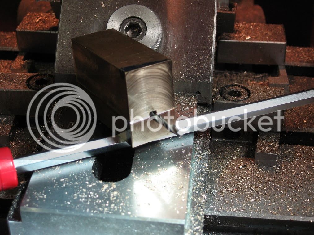
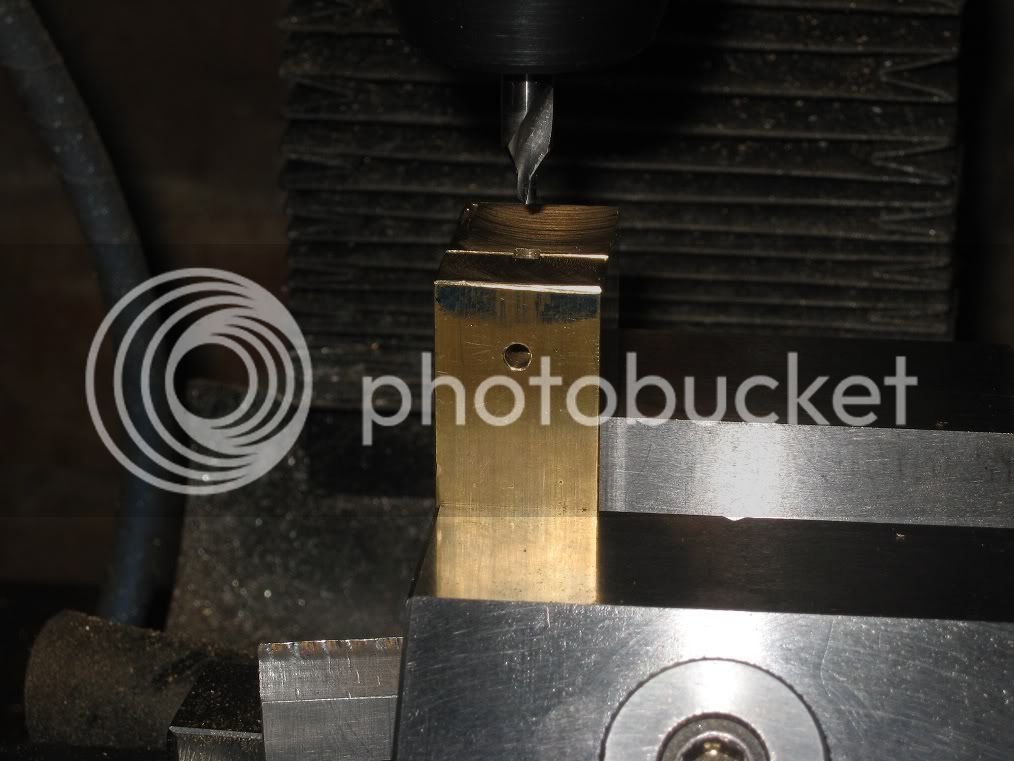
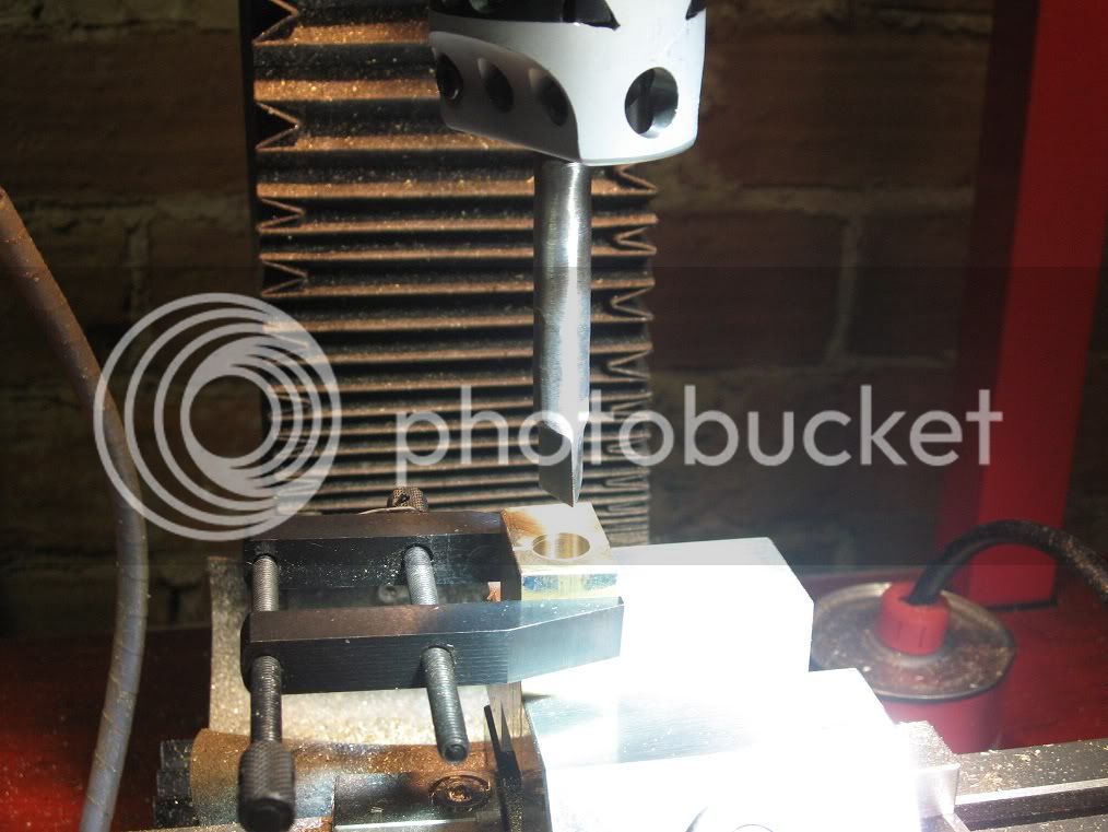
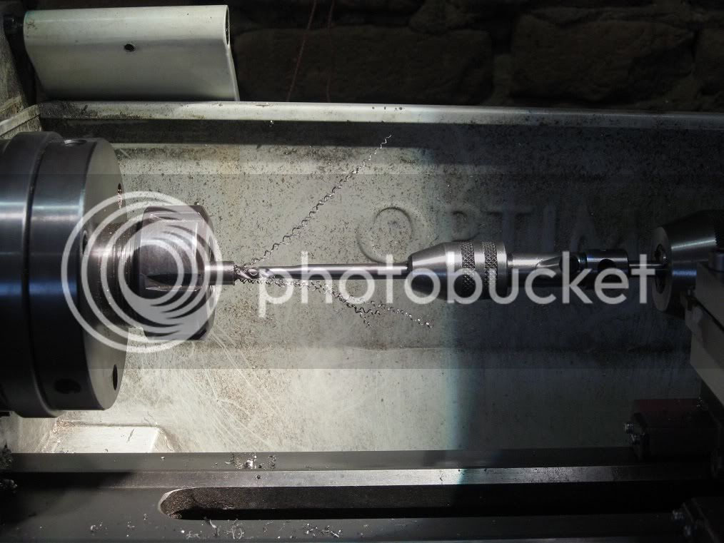
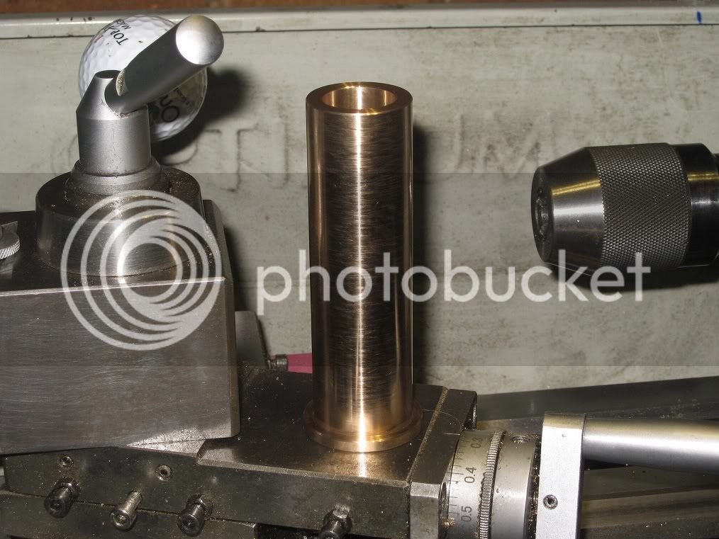
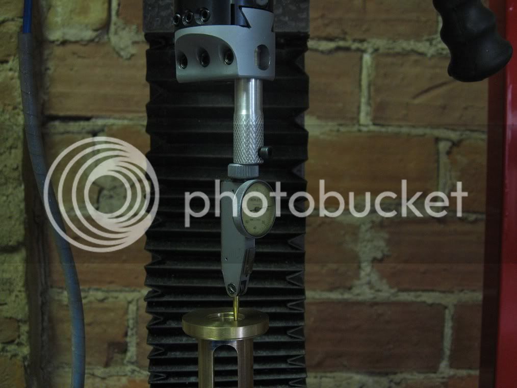
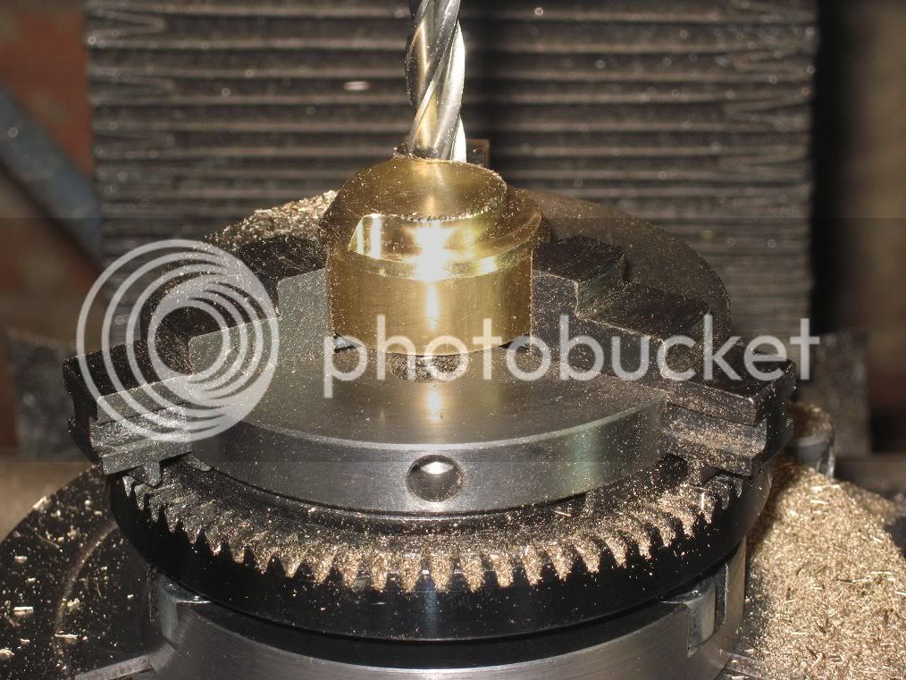
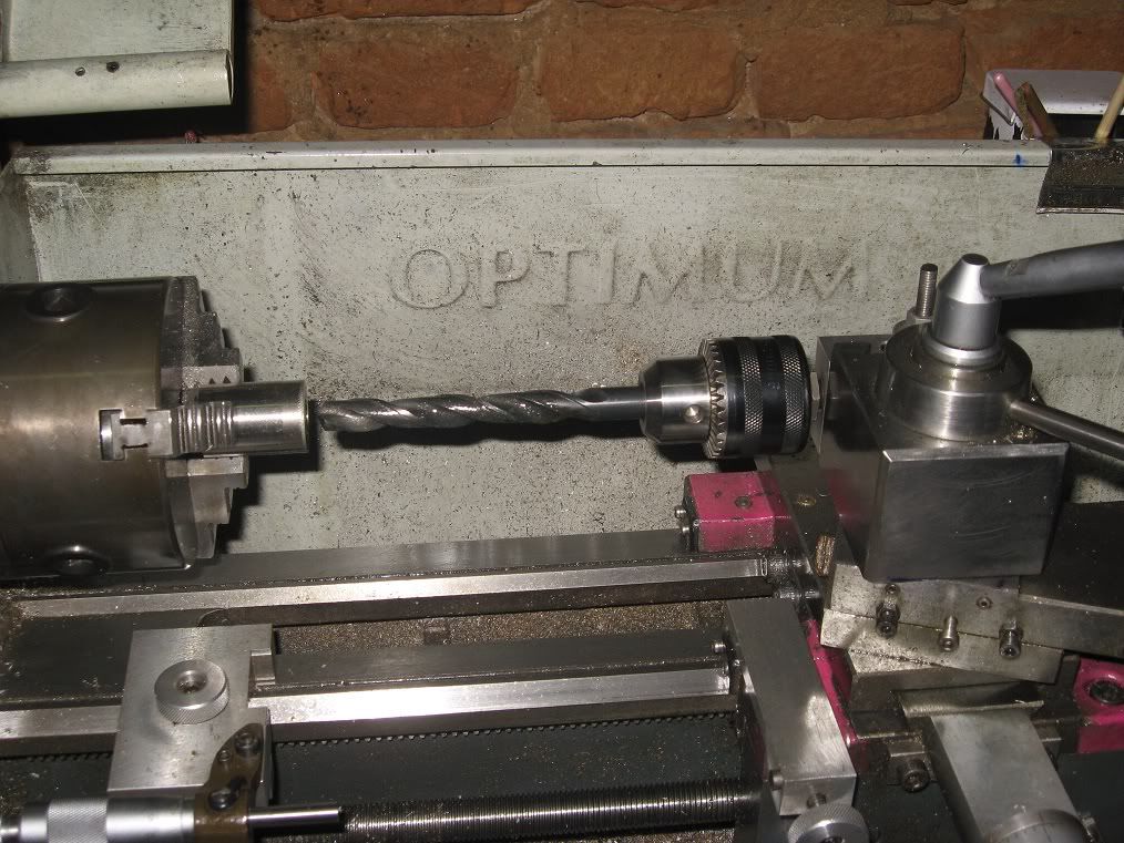
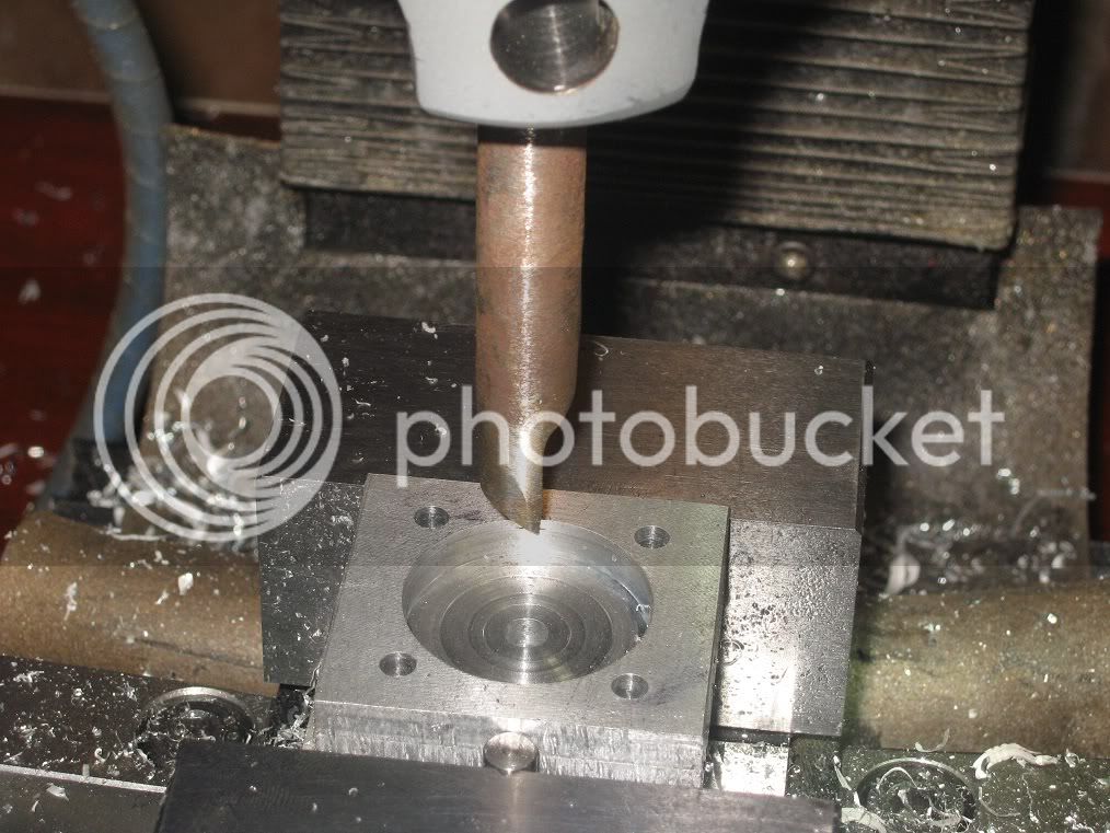
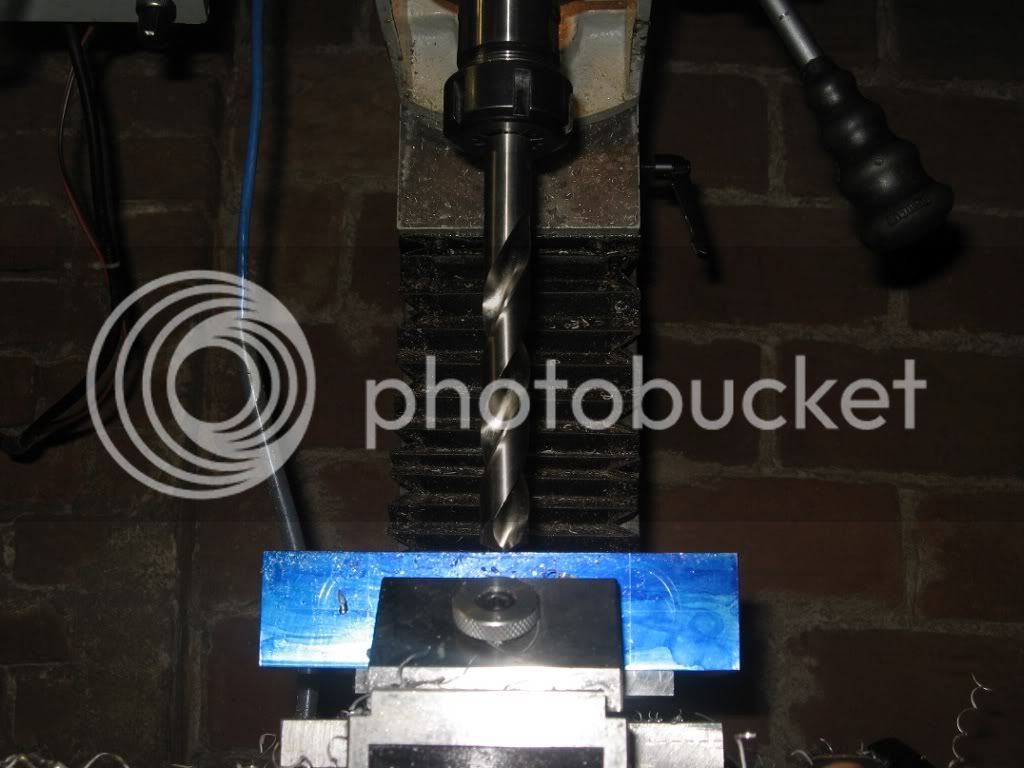
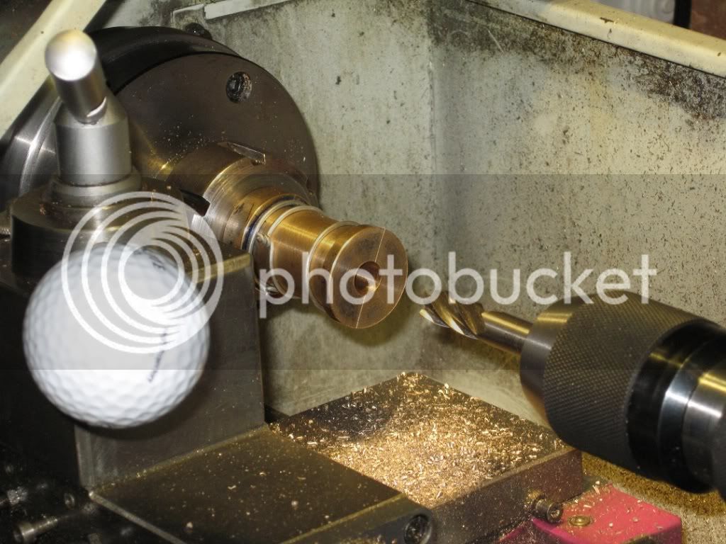
Drilling the hub to 10mm. then it will be bored to 11.85 and reamed to 12.

16Fw_IMG_0258.jpg


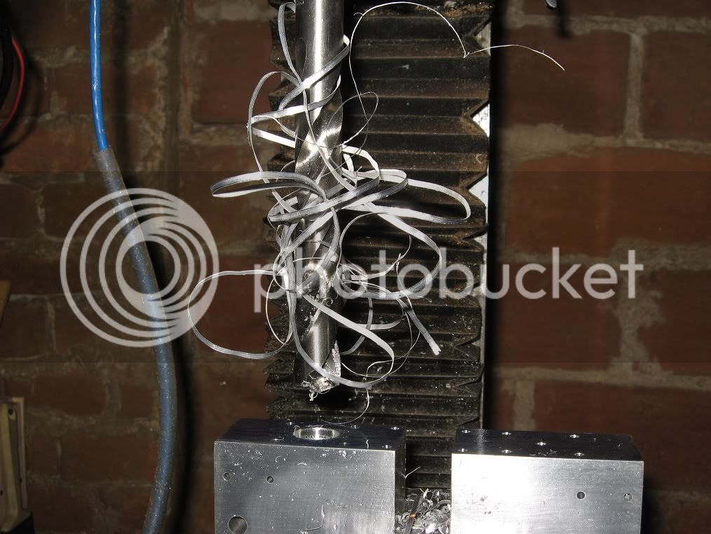
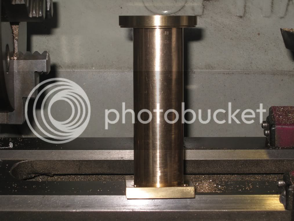
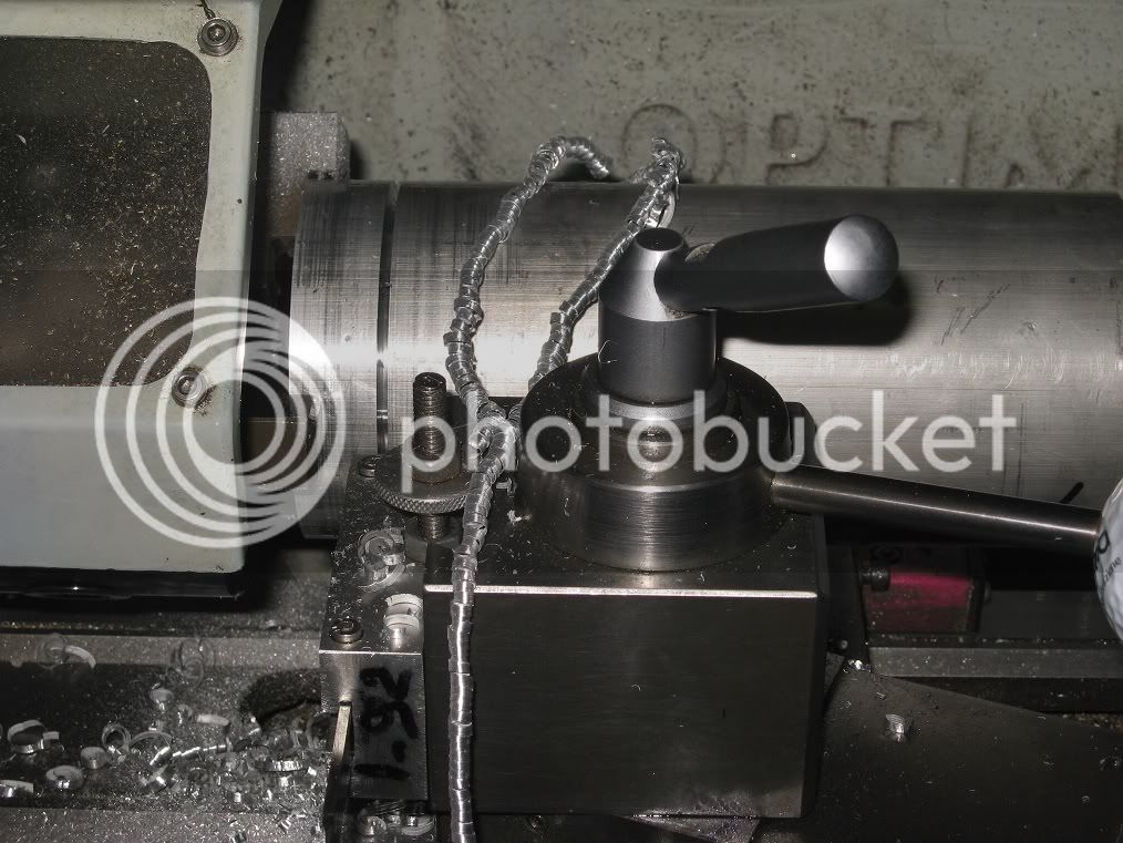
Parting stock for the ring. I rarely get swarfs like those while parting: I suppose the tool happened to be dead square on this occasion.

16Fw_IMG_0260.jpg


End of parting. Had to increase the tool overhang three times to get it done. The final 5 or 6mm portion was hacksawed.


16Fw_IMG_0262.jpg


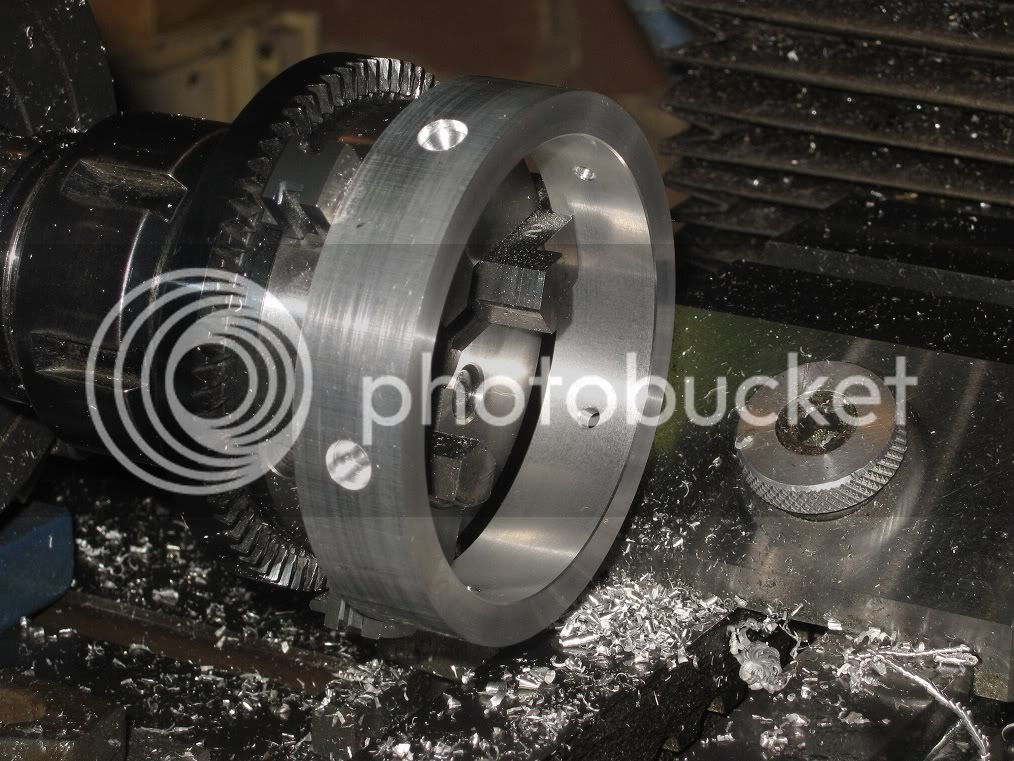
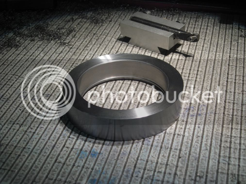
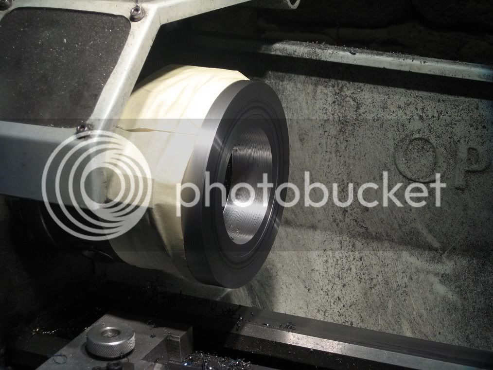
Trepanning the ring..

16Fw_IMG_0264.jpg


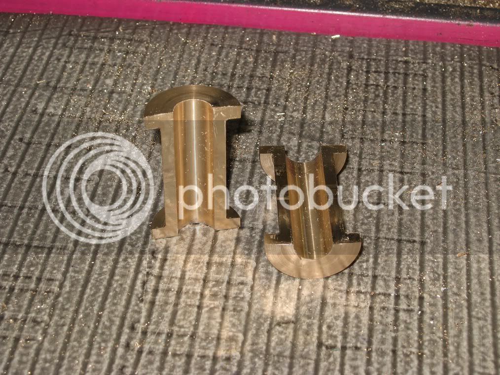
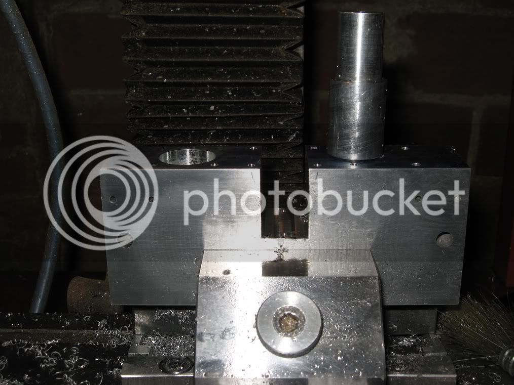
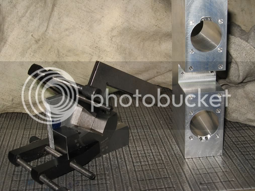
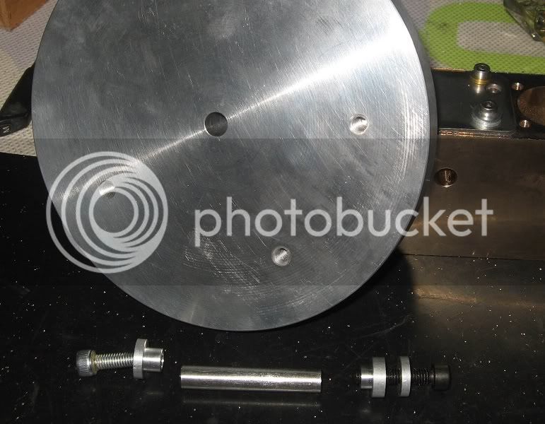
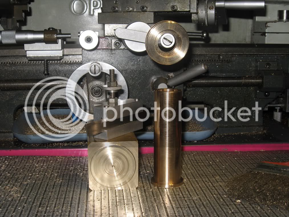
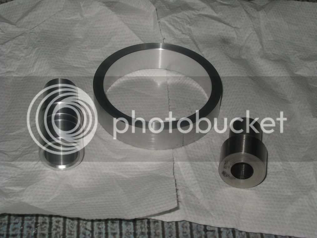
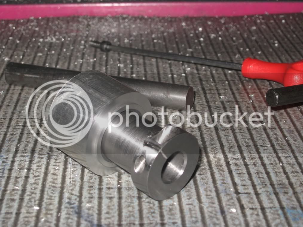
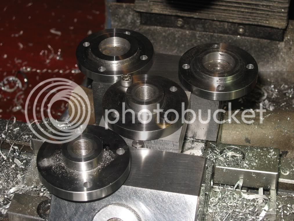
The still unfinished hub, ring, and an aluminum sleeve I made to fit the hub.

16Fw_IMG_0268.jpg

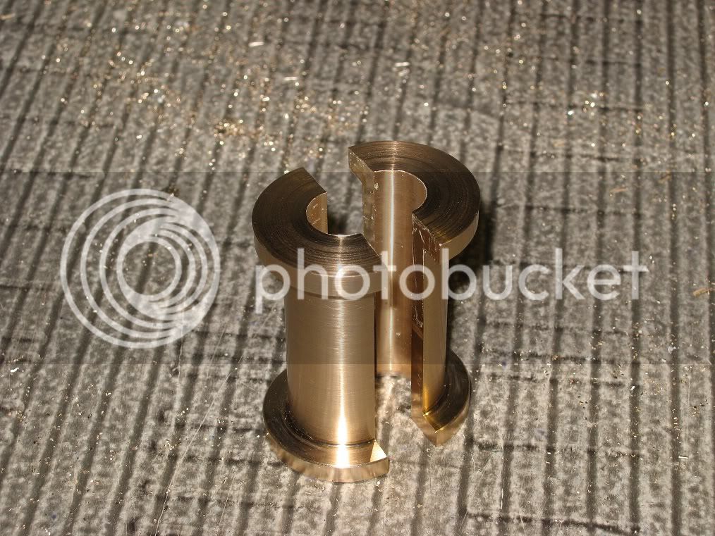
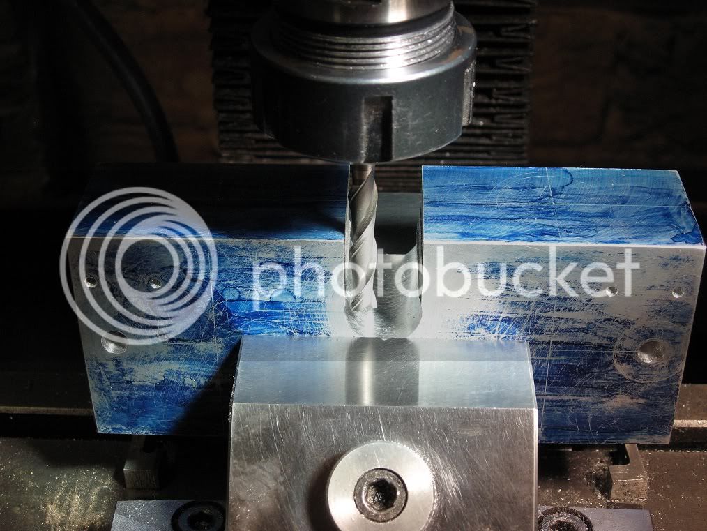
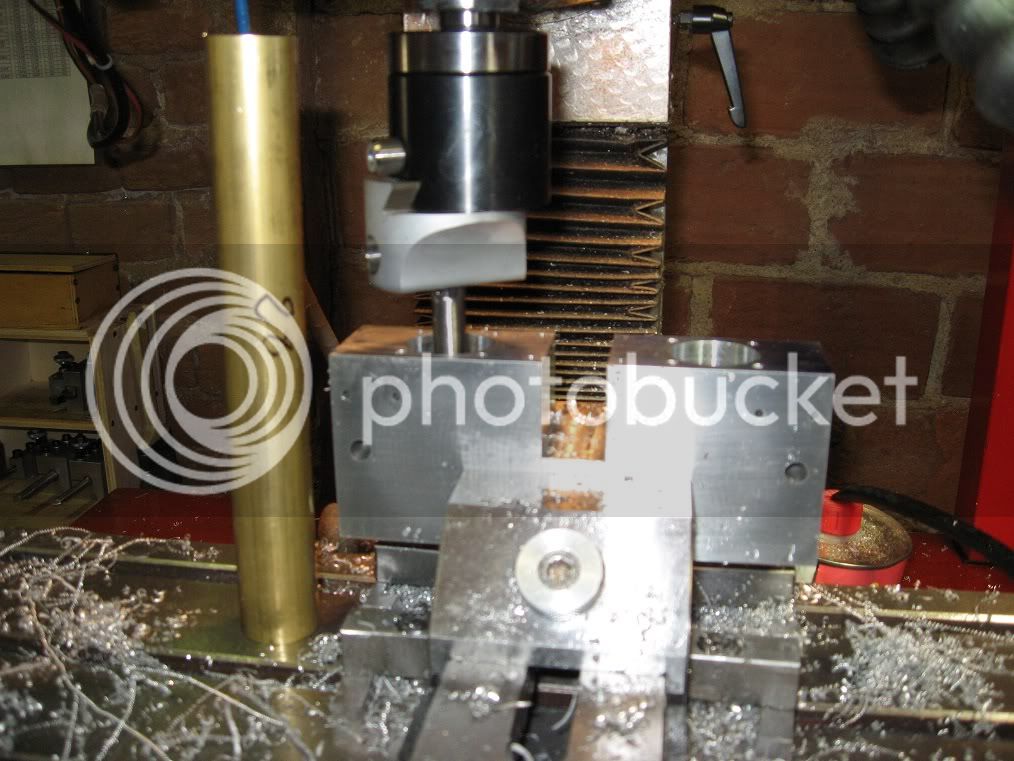
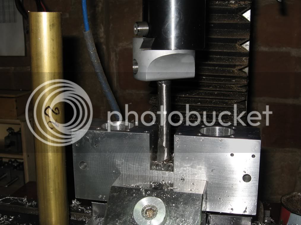
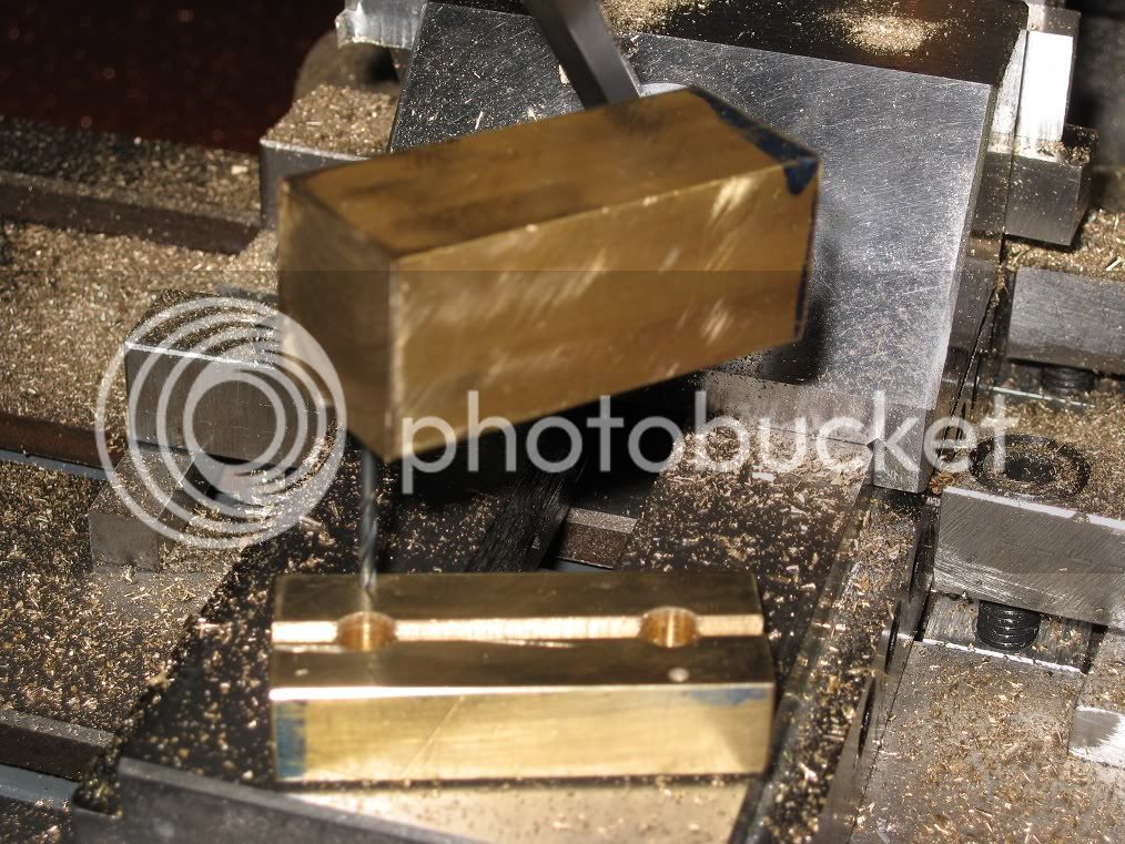
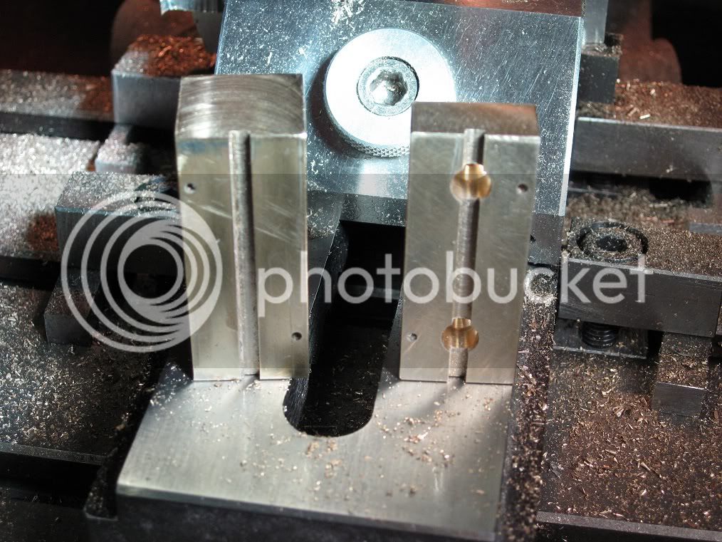
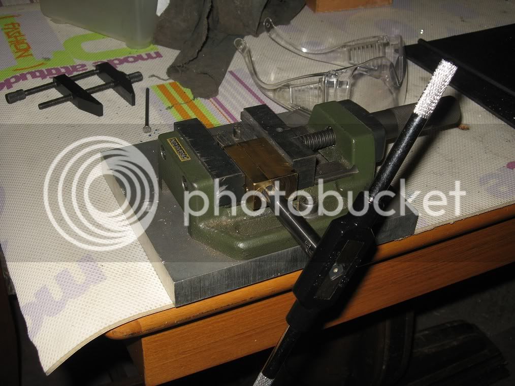
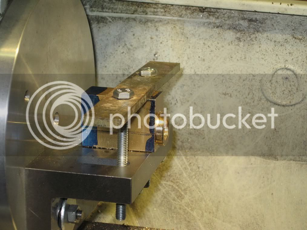
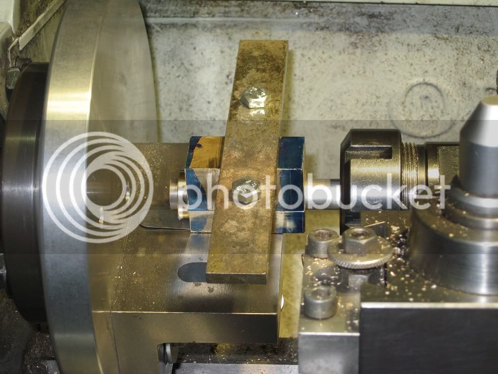
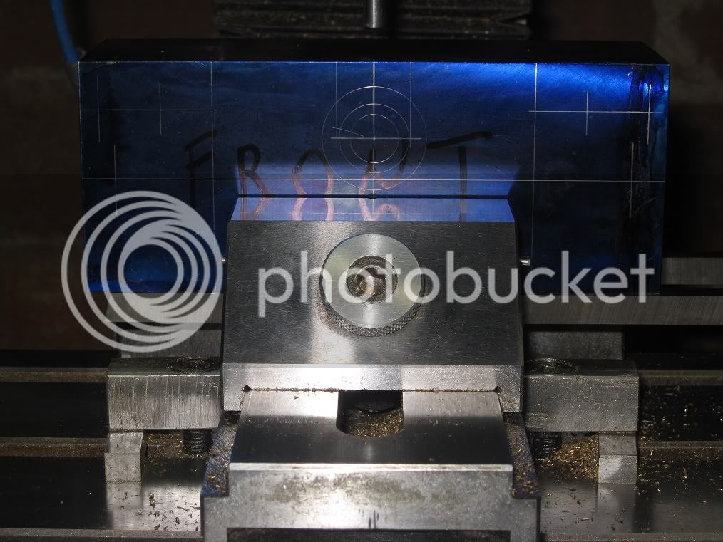
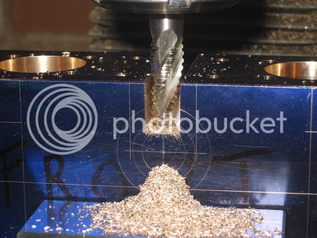
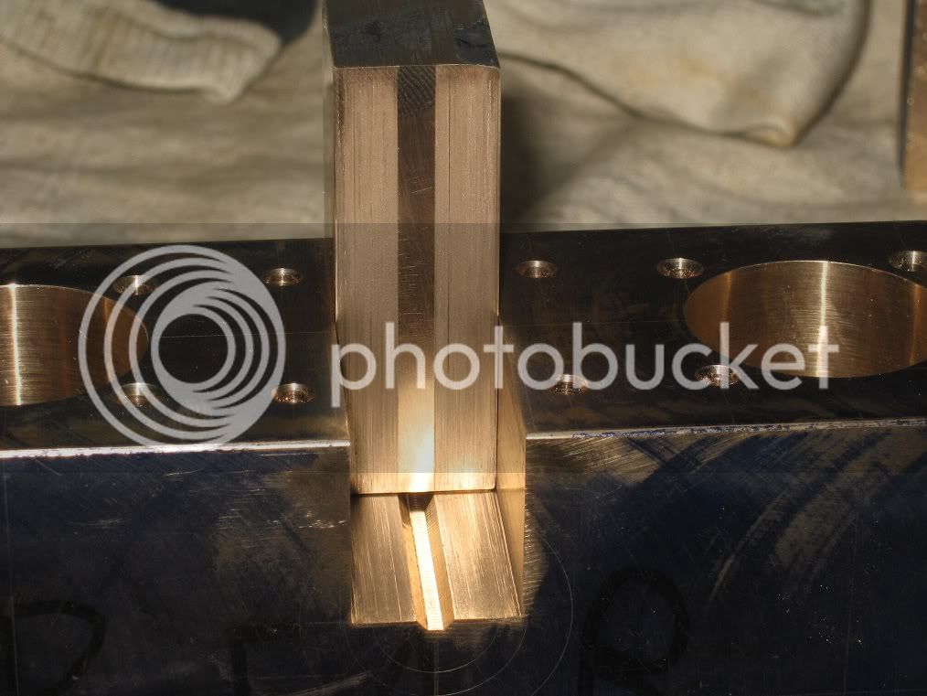
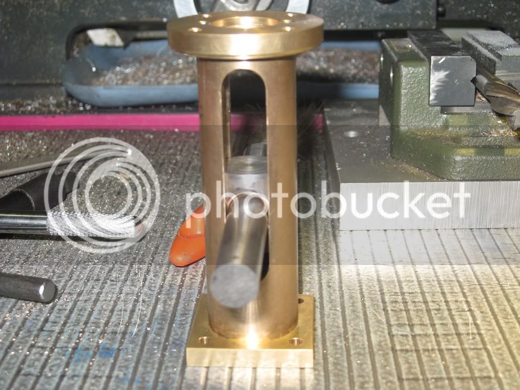
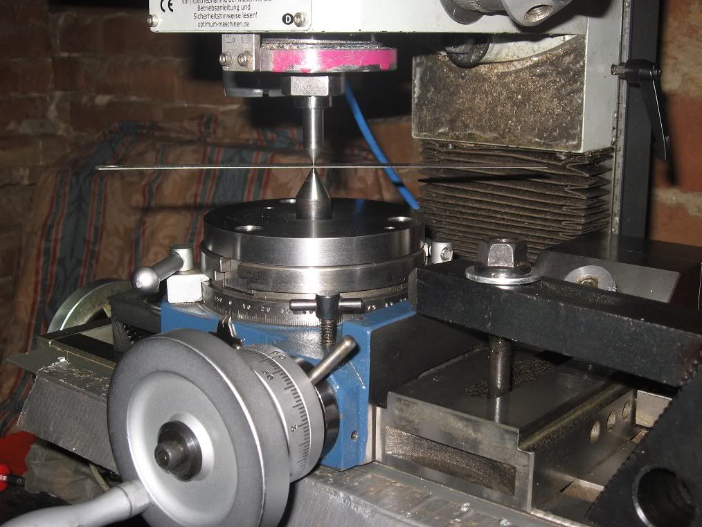
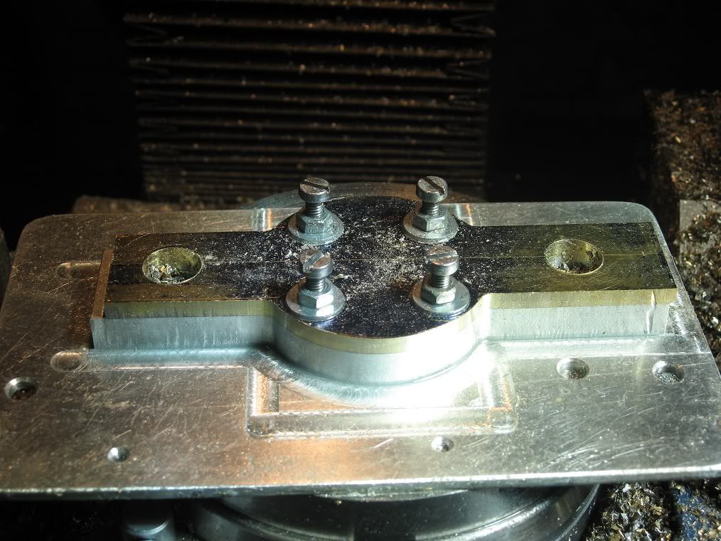
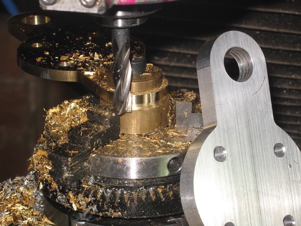
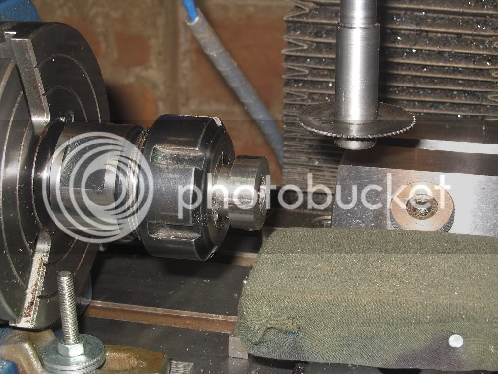
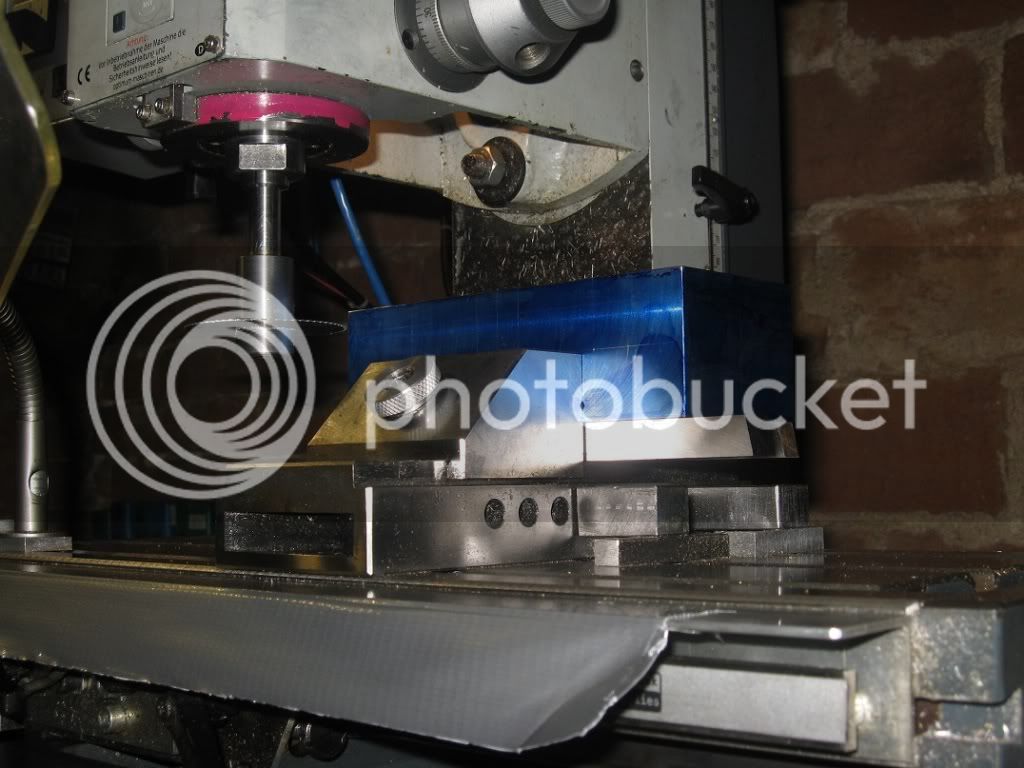
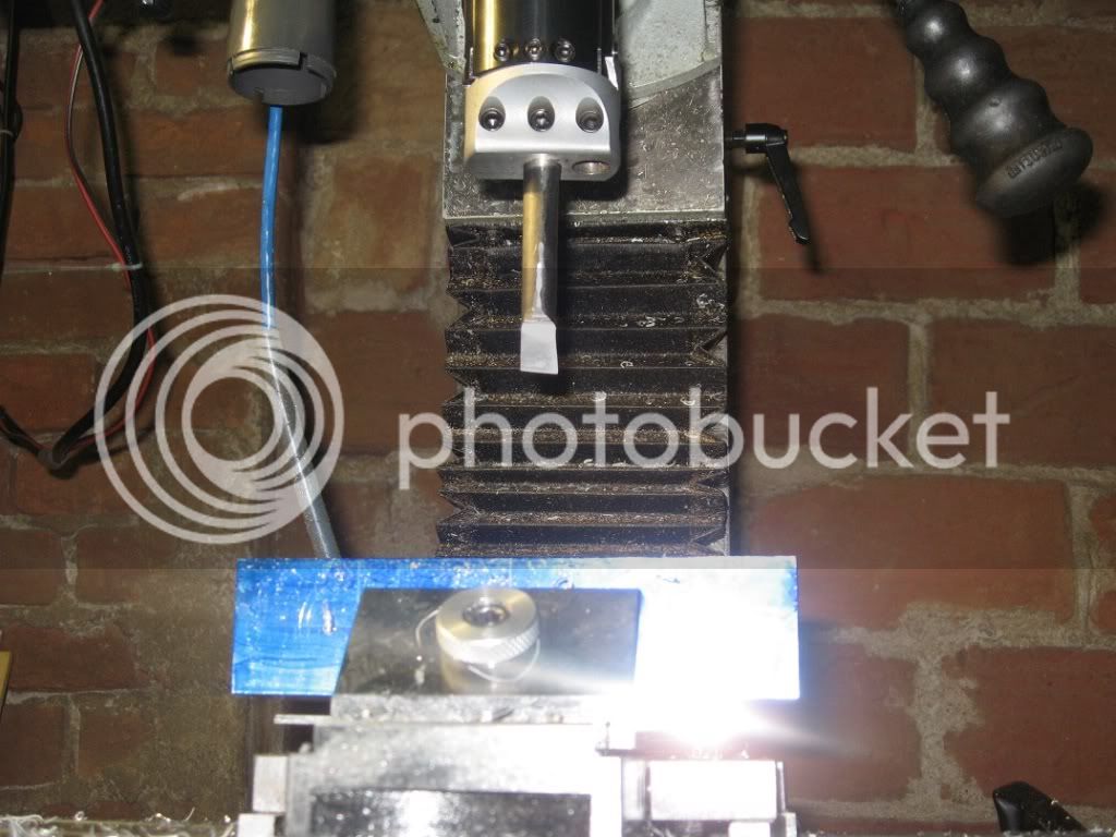
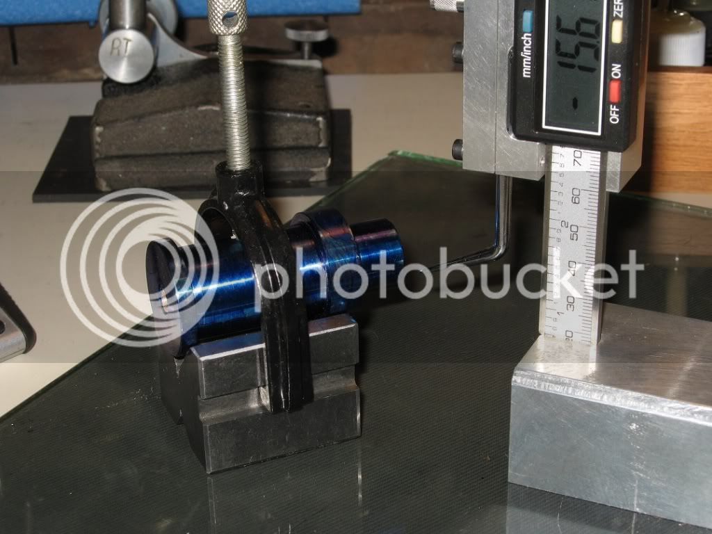
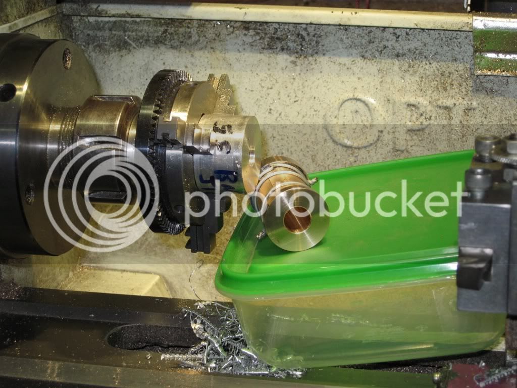
Slitting the hub. The RT was really not a must for this job, but was handy for holding the workpiece and will be ready for the next operations.


16Fw_IMG_0270.jpg


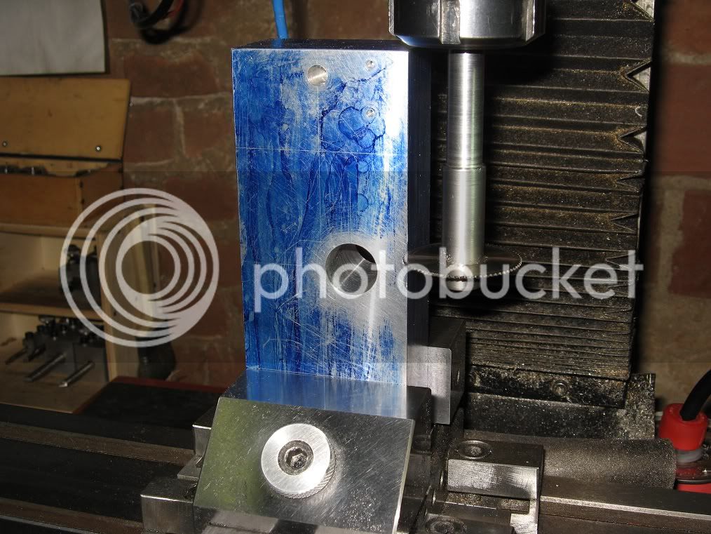
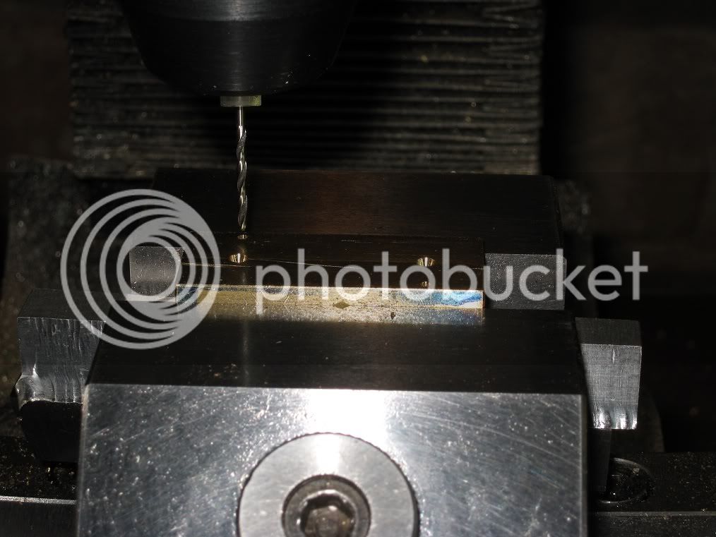
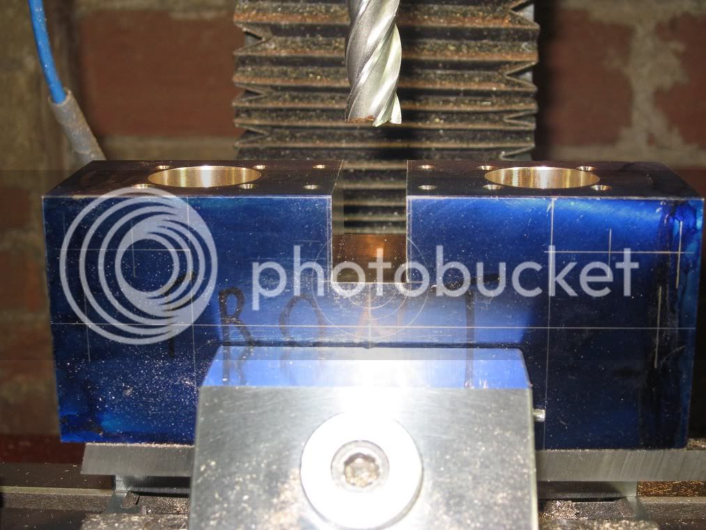
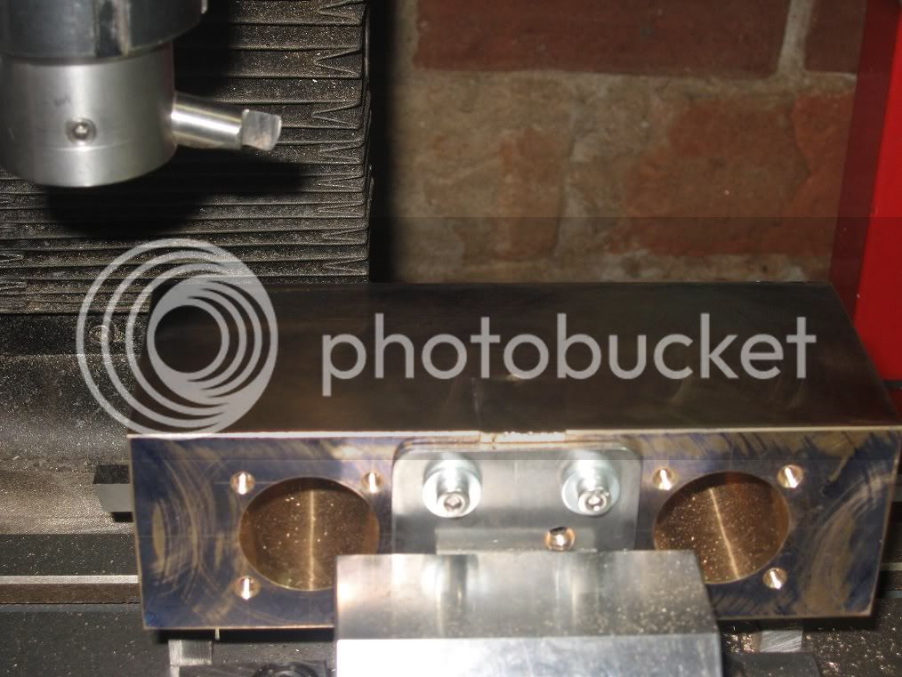
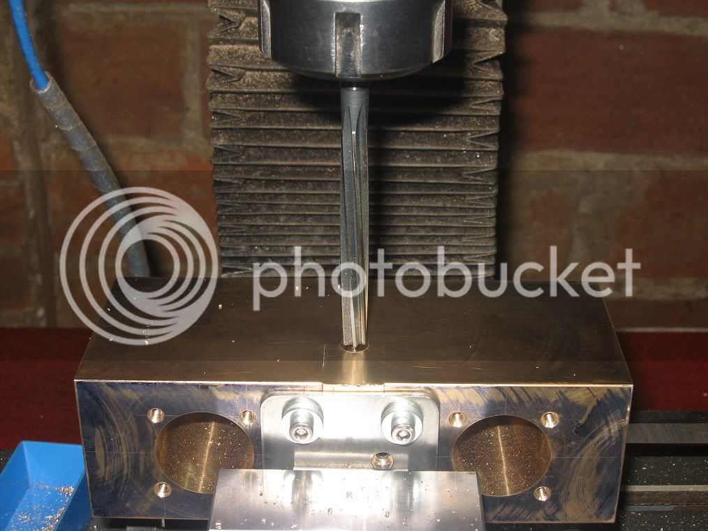
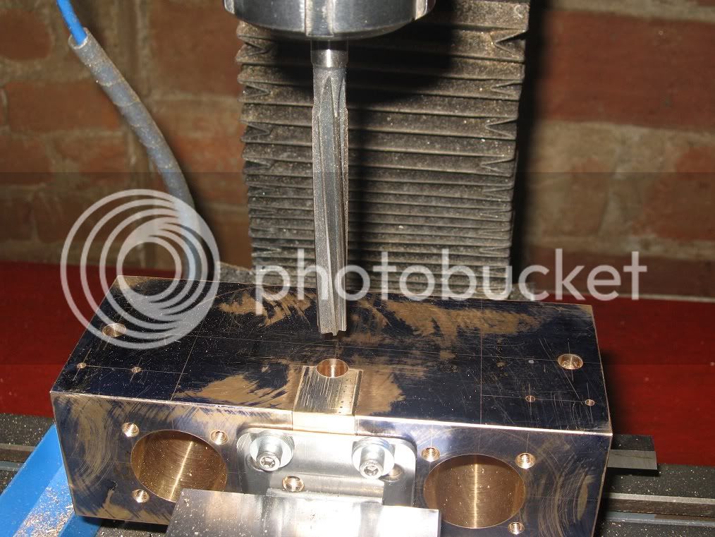
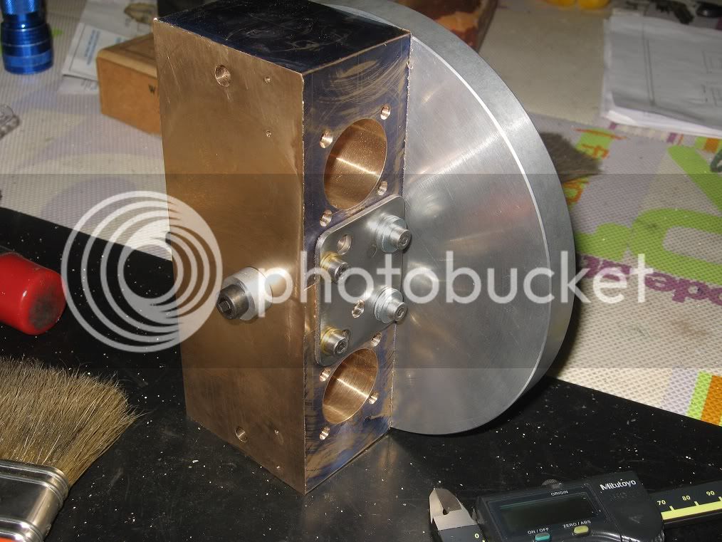
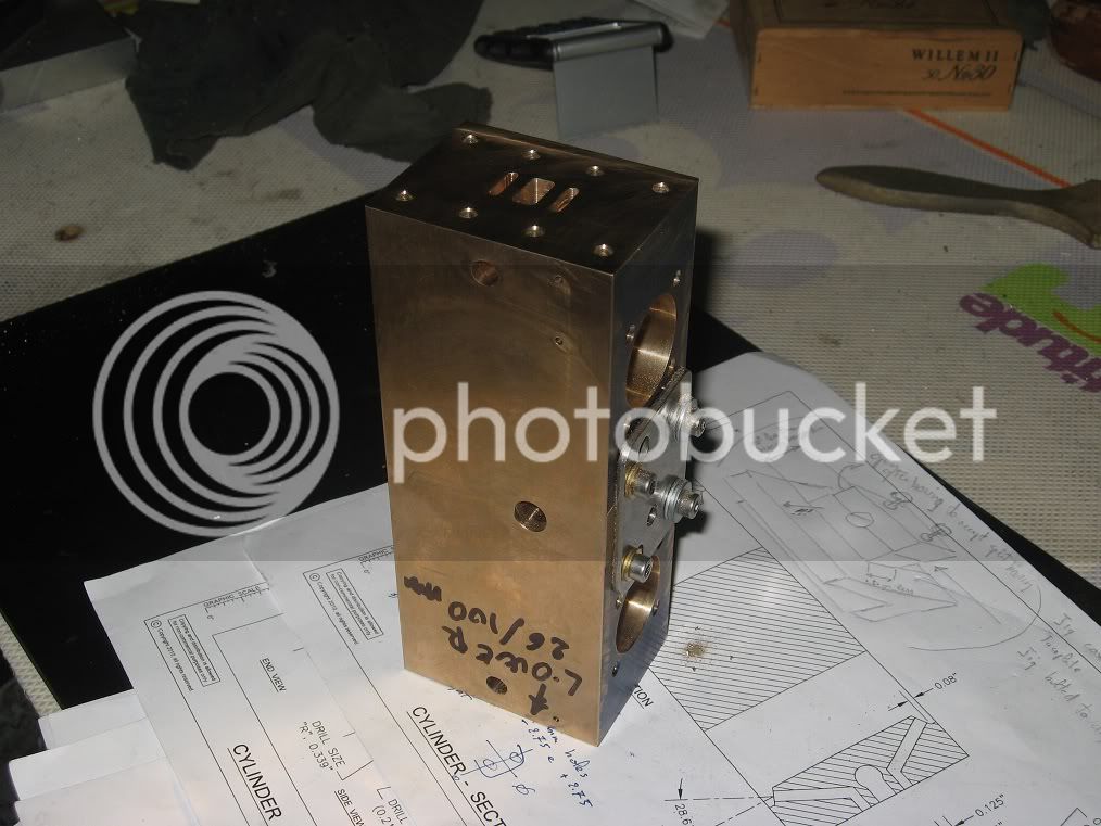
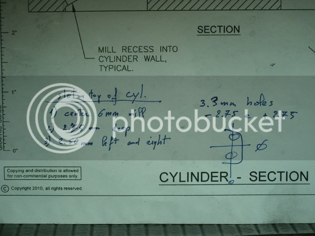
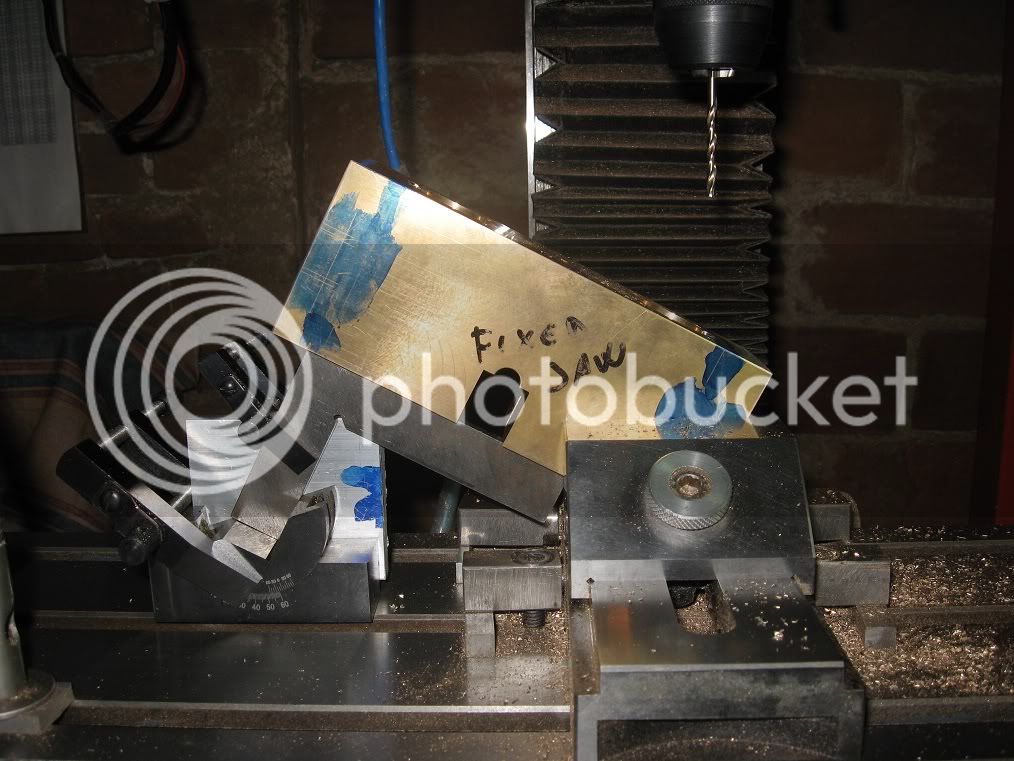
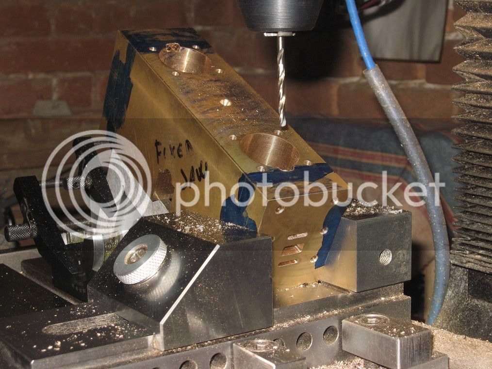
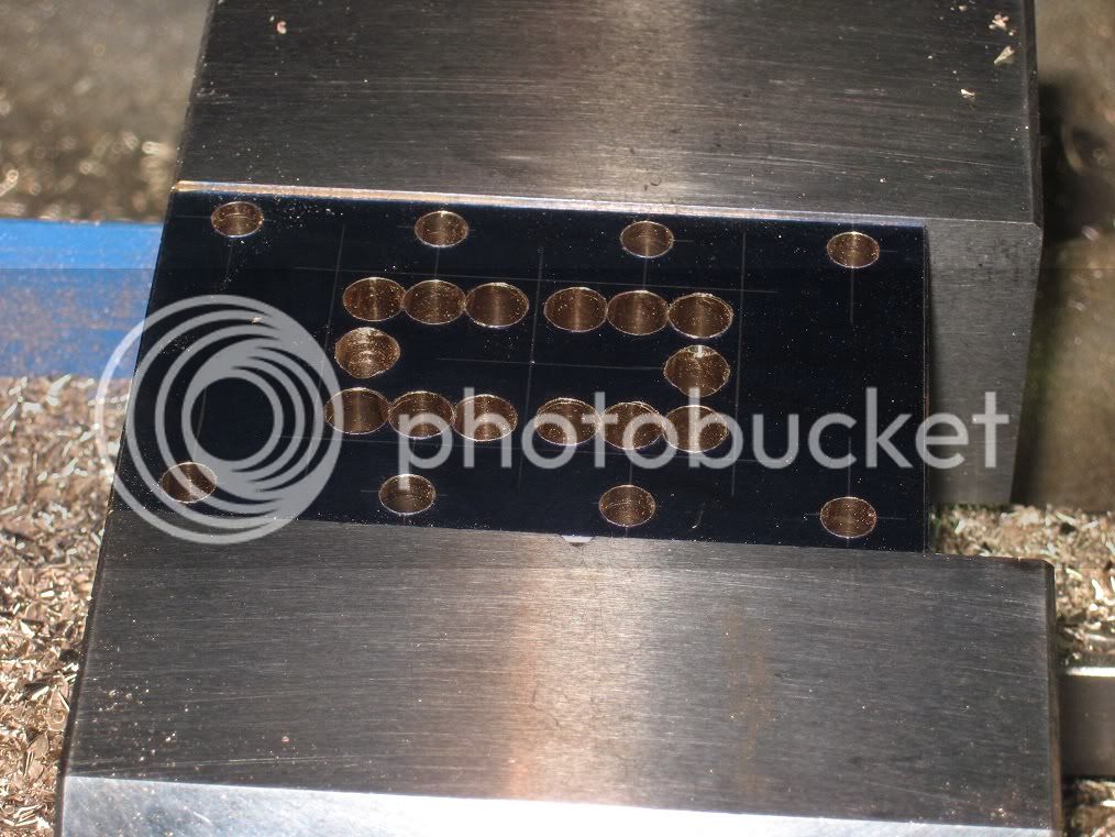
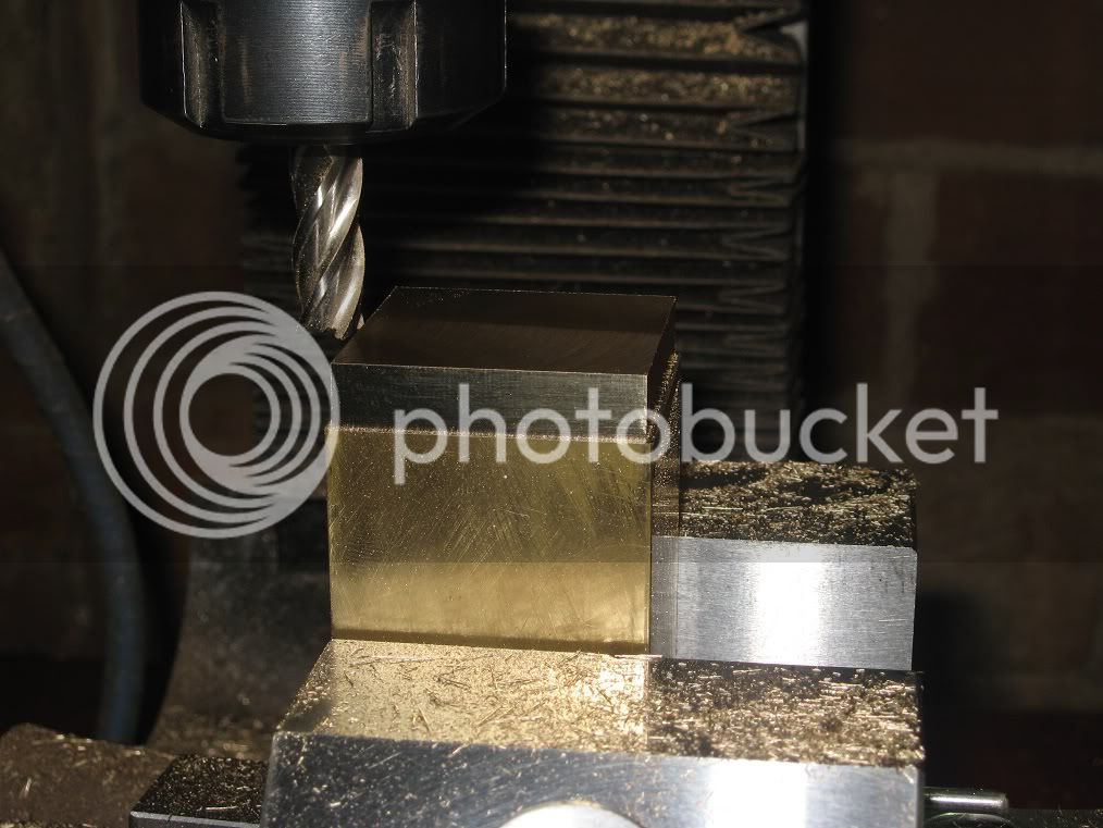
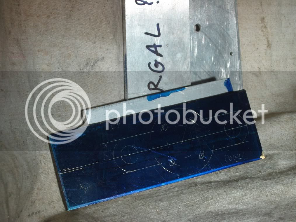
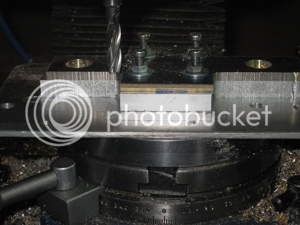
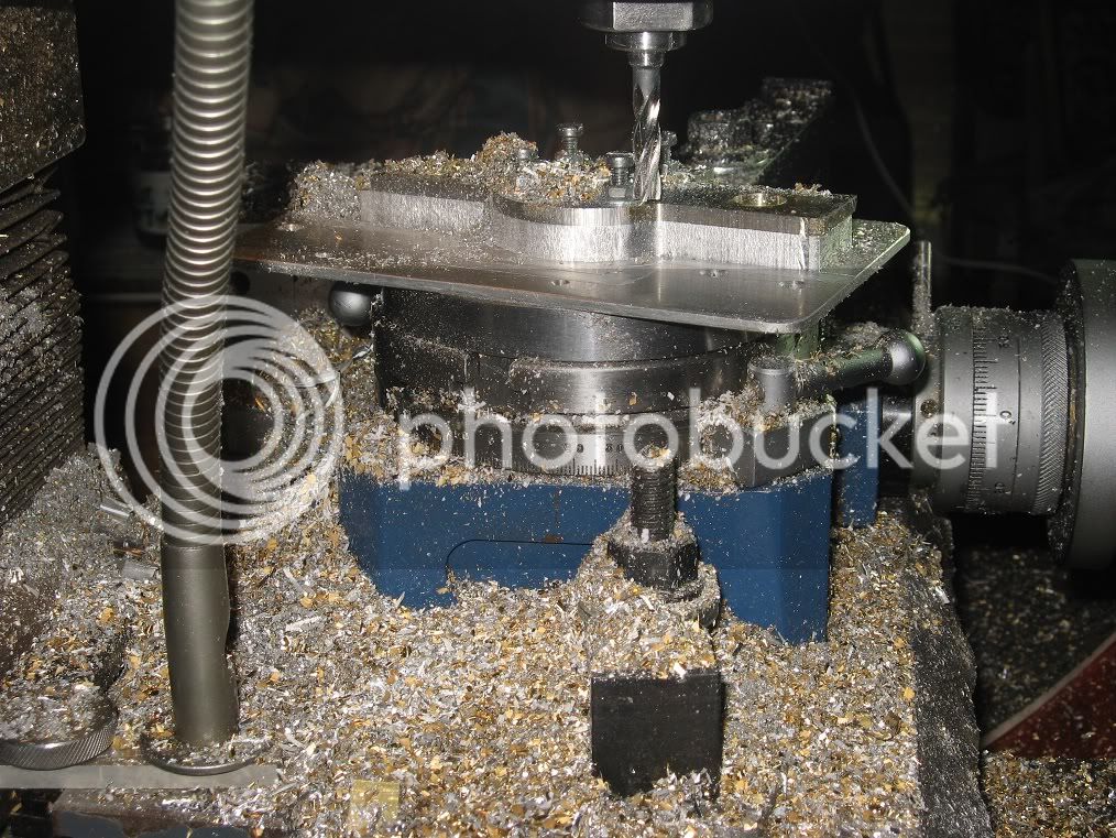
..of milling the flats for the columns and drilling the holes for the studs.
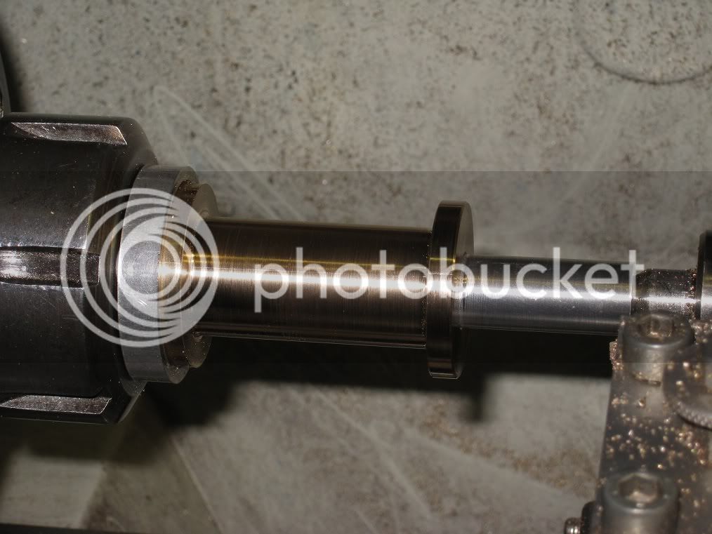
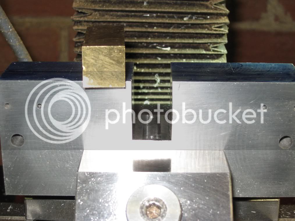
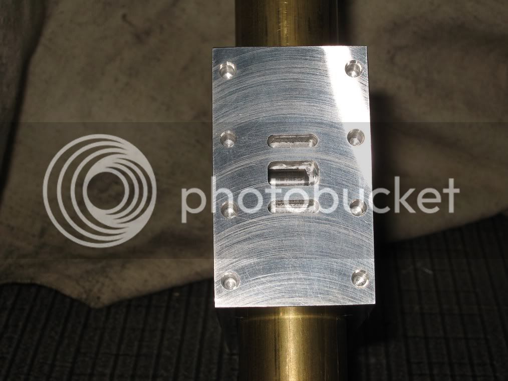
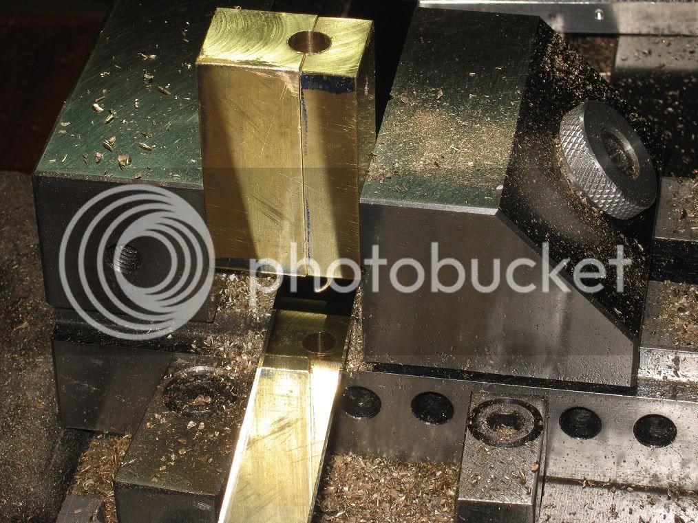
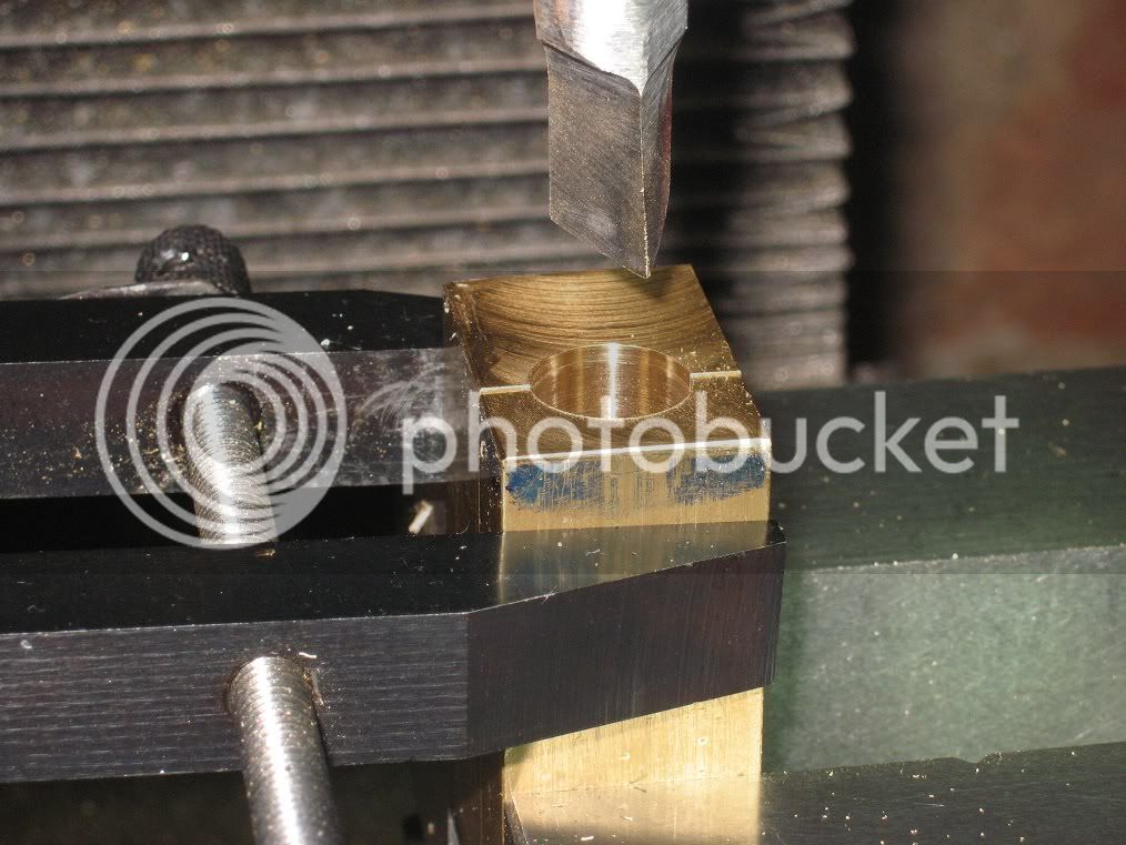
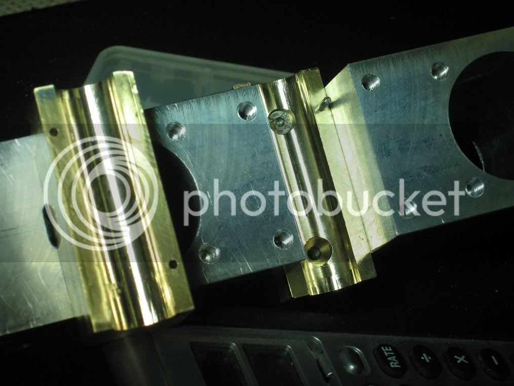
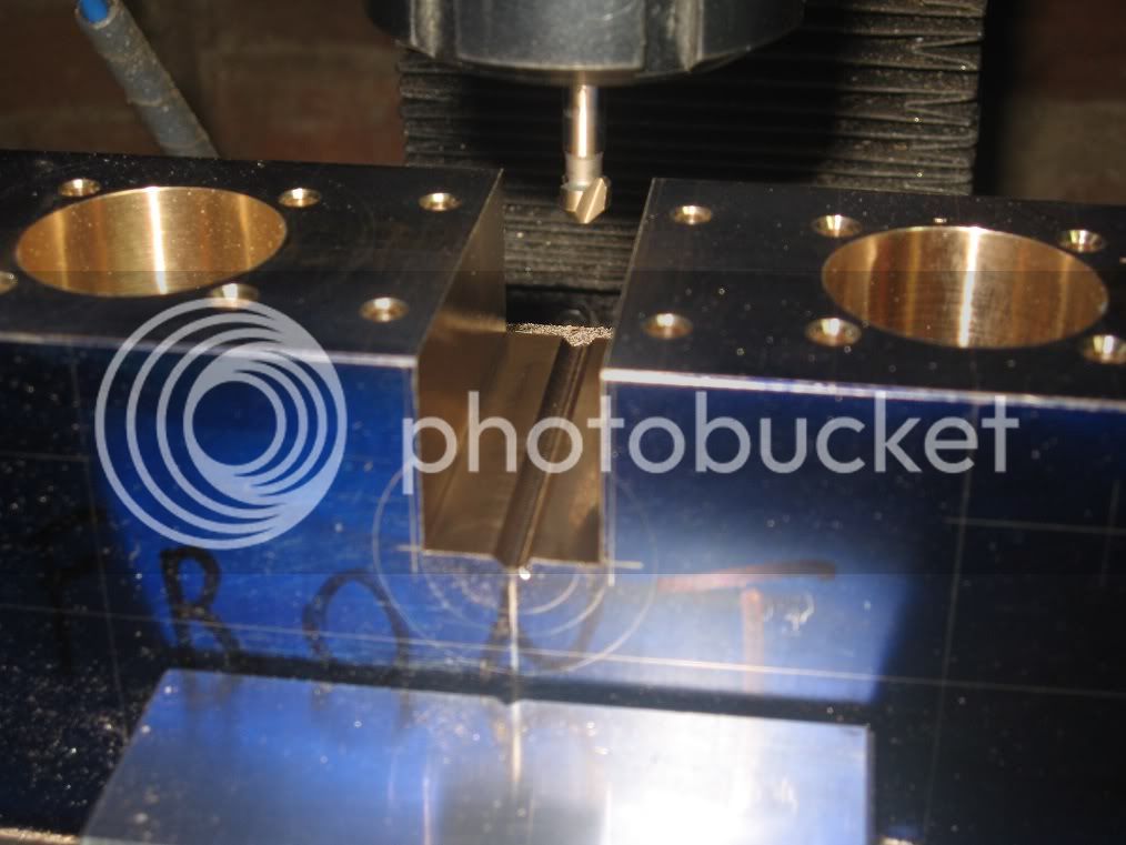
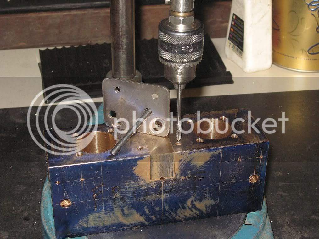
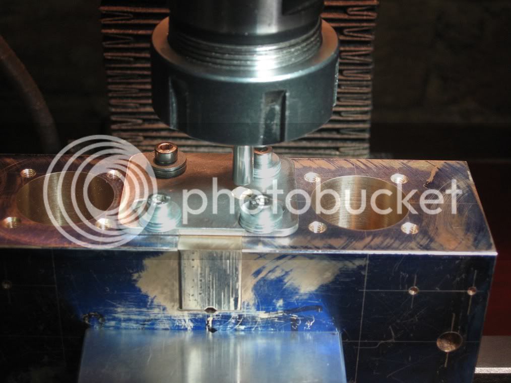
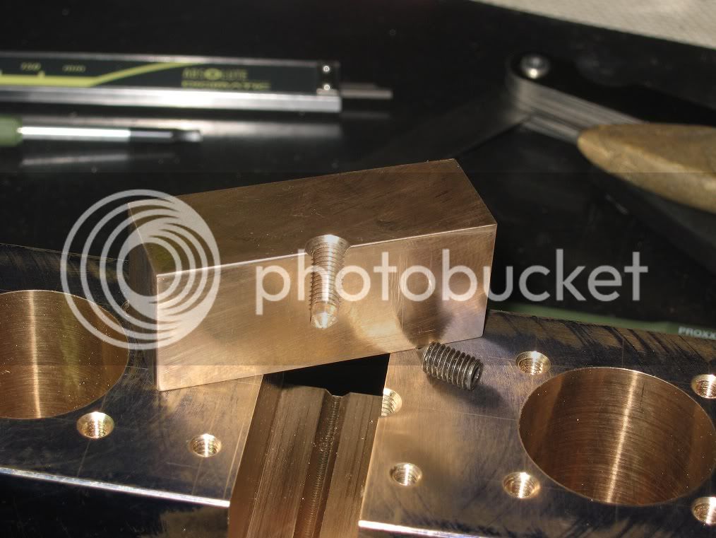
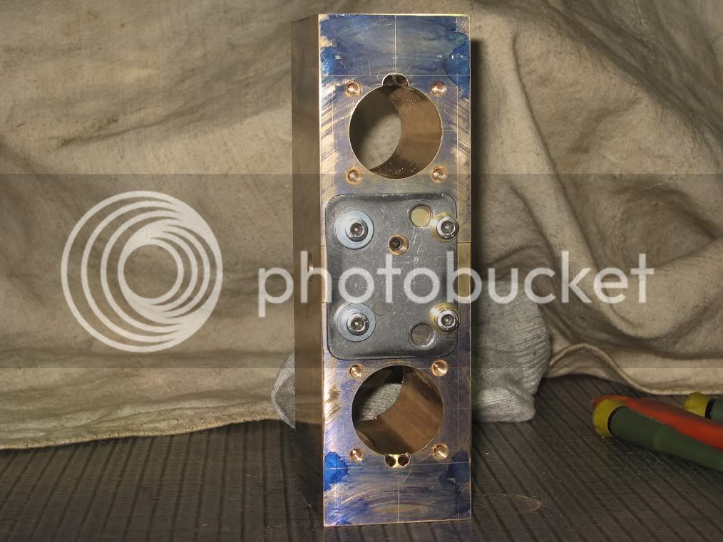
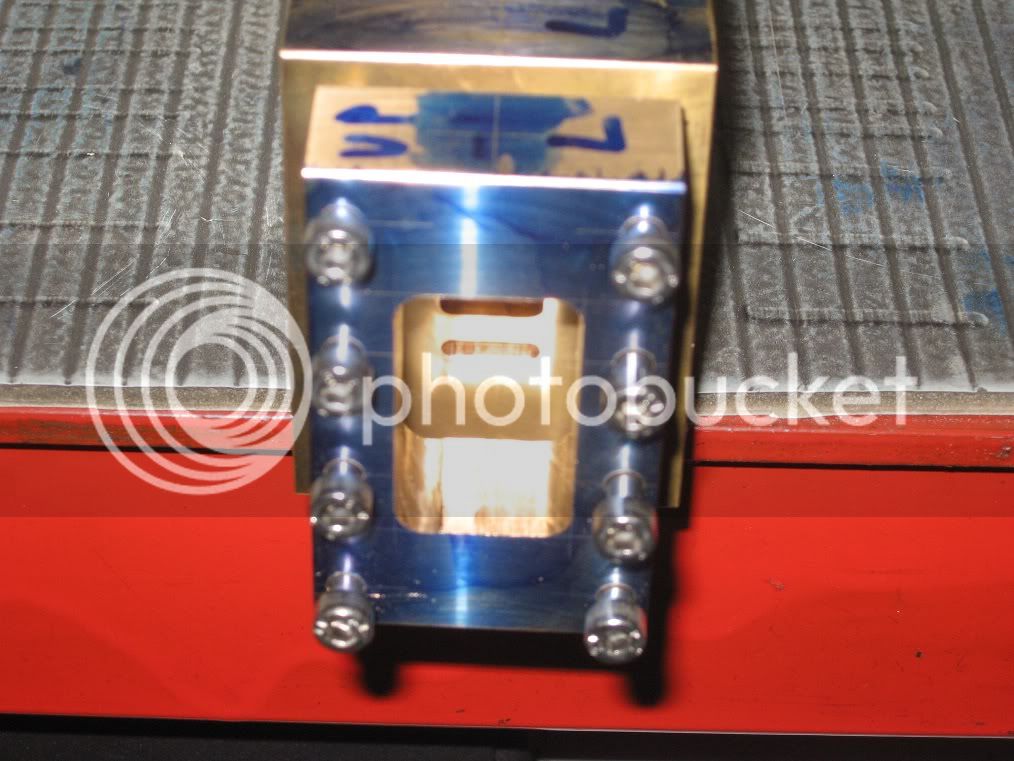
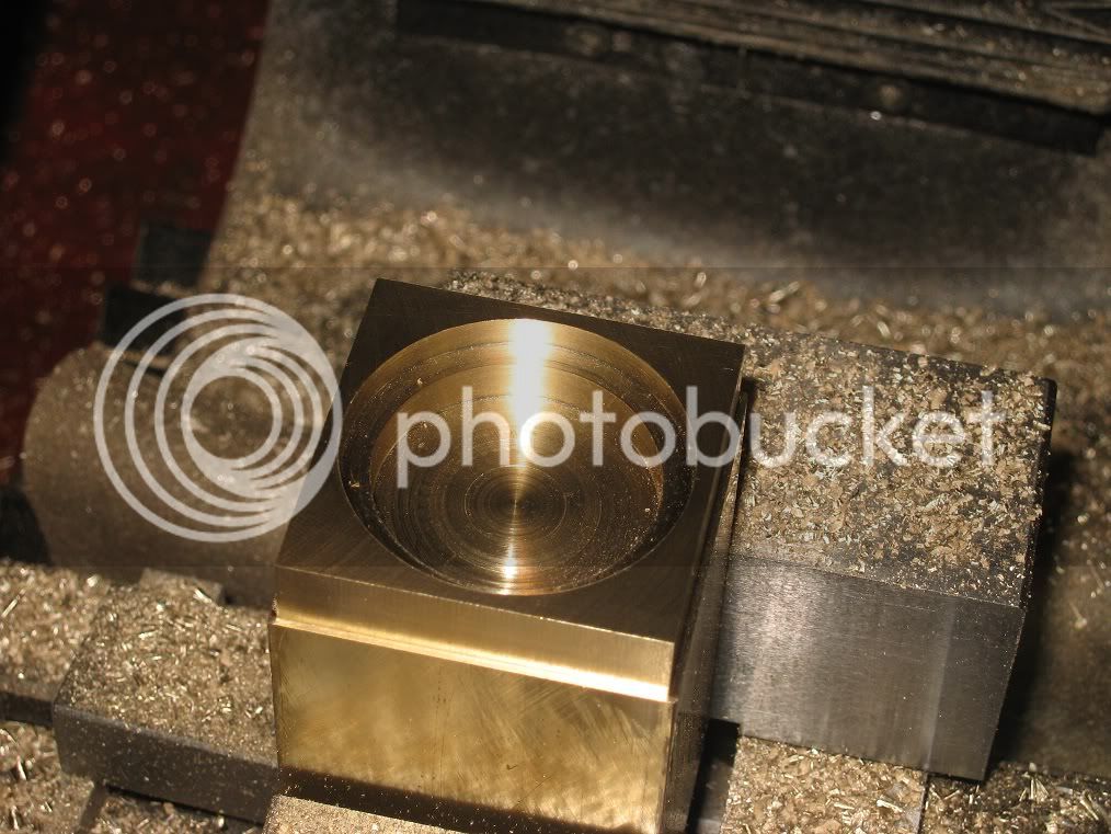
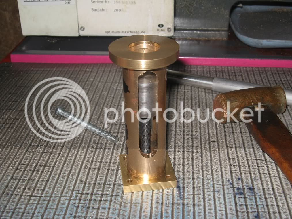
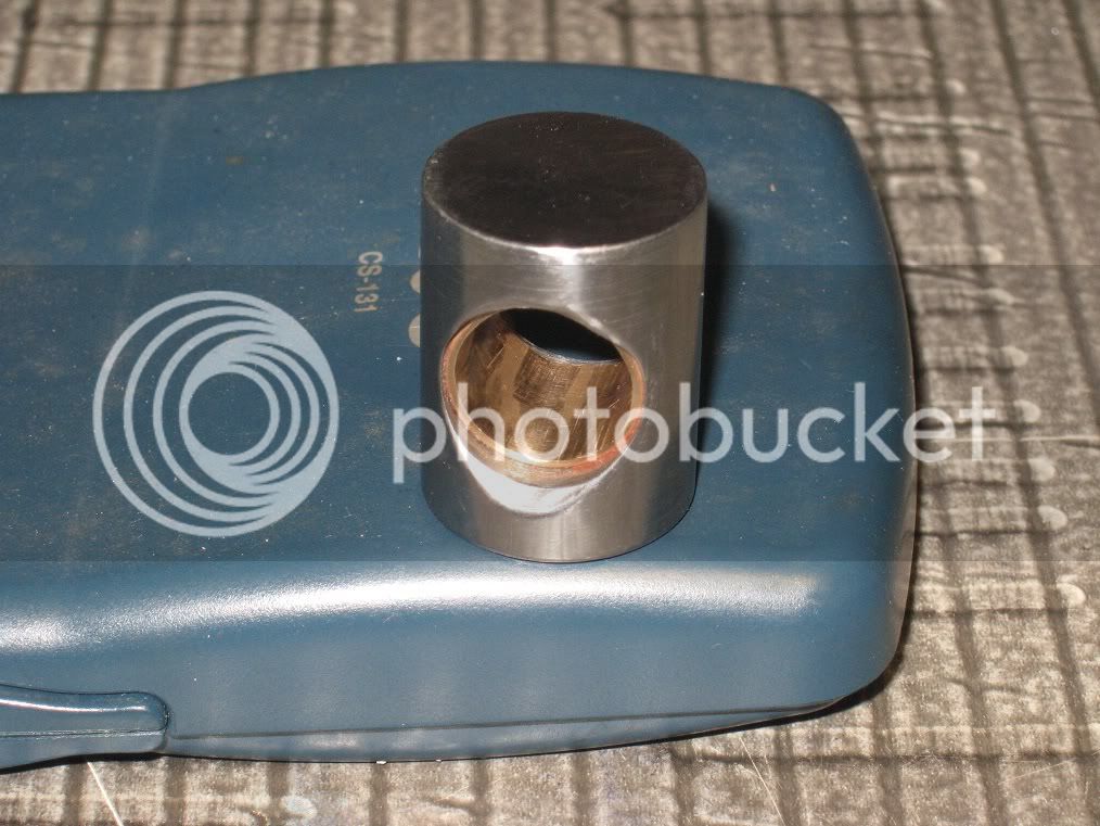
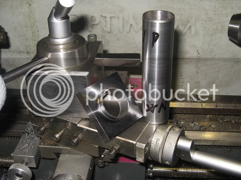
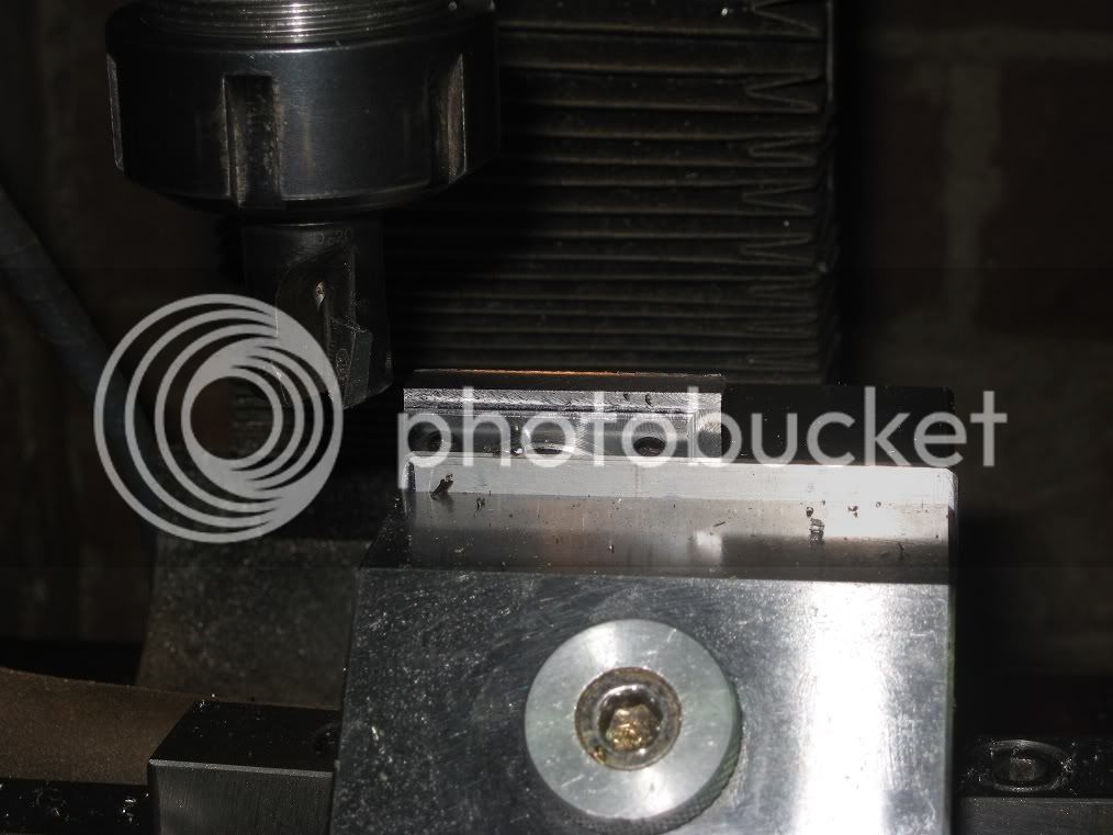
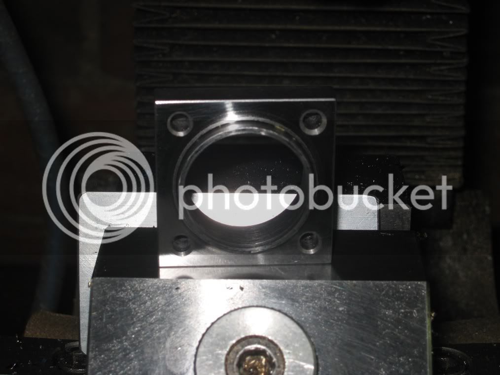
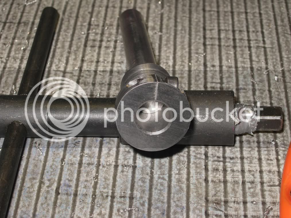
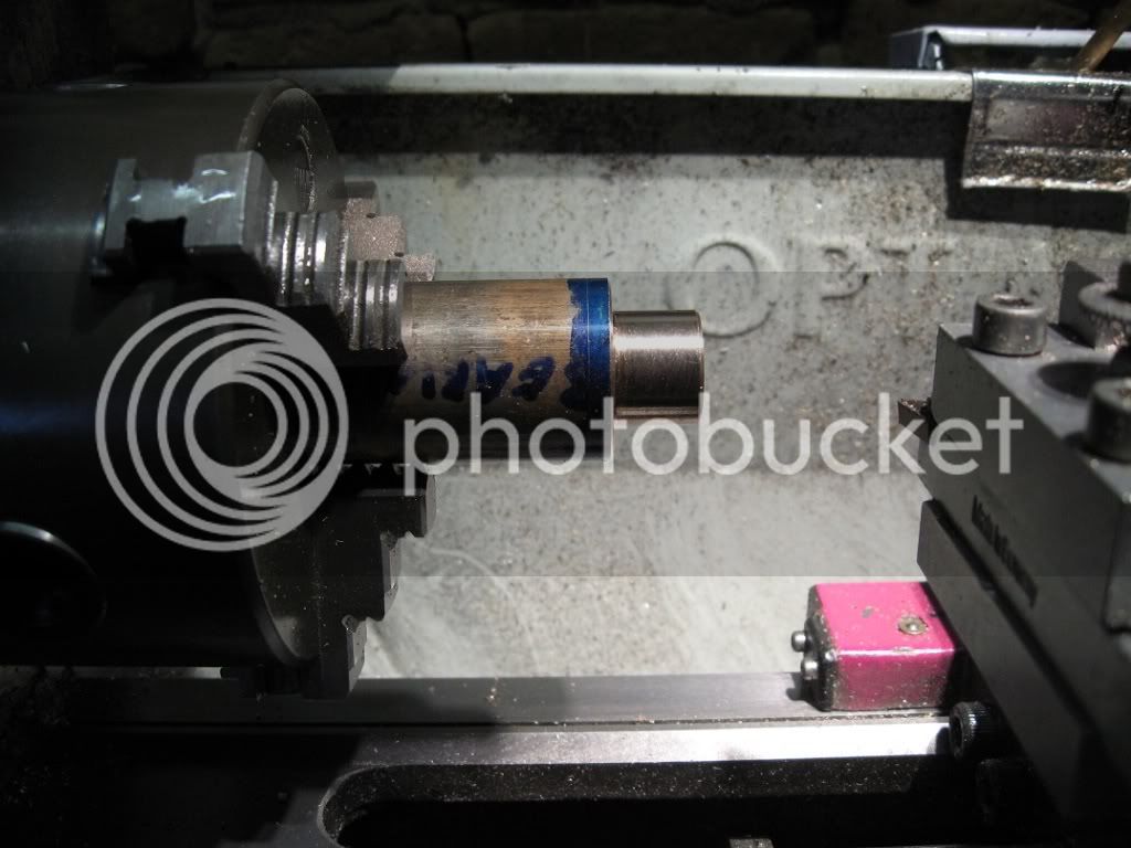
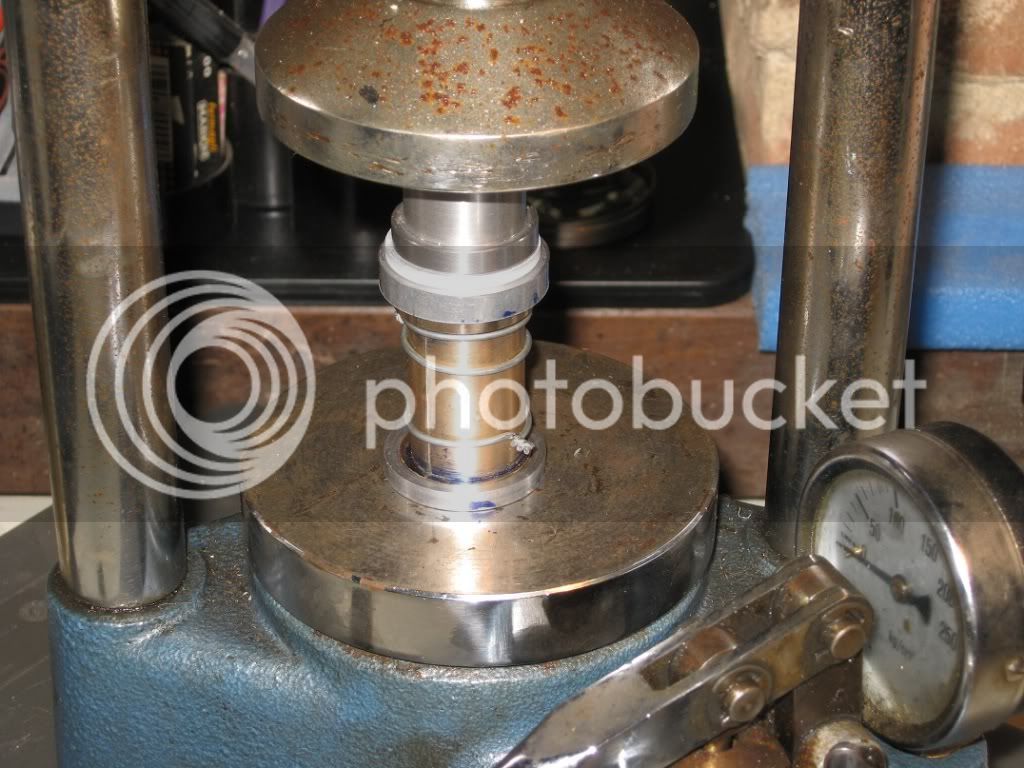
In the meanwhile I had drilled and tapped the hole for the locking screw, milled the pocket for the head and pressed the sleeve to hide the halfway cut as Chuck had explained into this thread
< http://www.homemodelenginemachinist.com/index.php?topic=11471.0 >
Thanks again, Chuck!

16Fw_IMG_0277.jpg

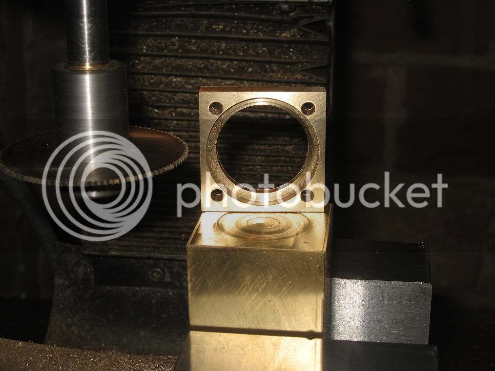
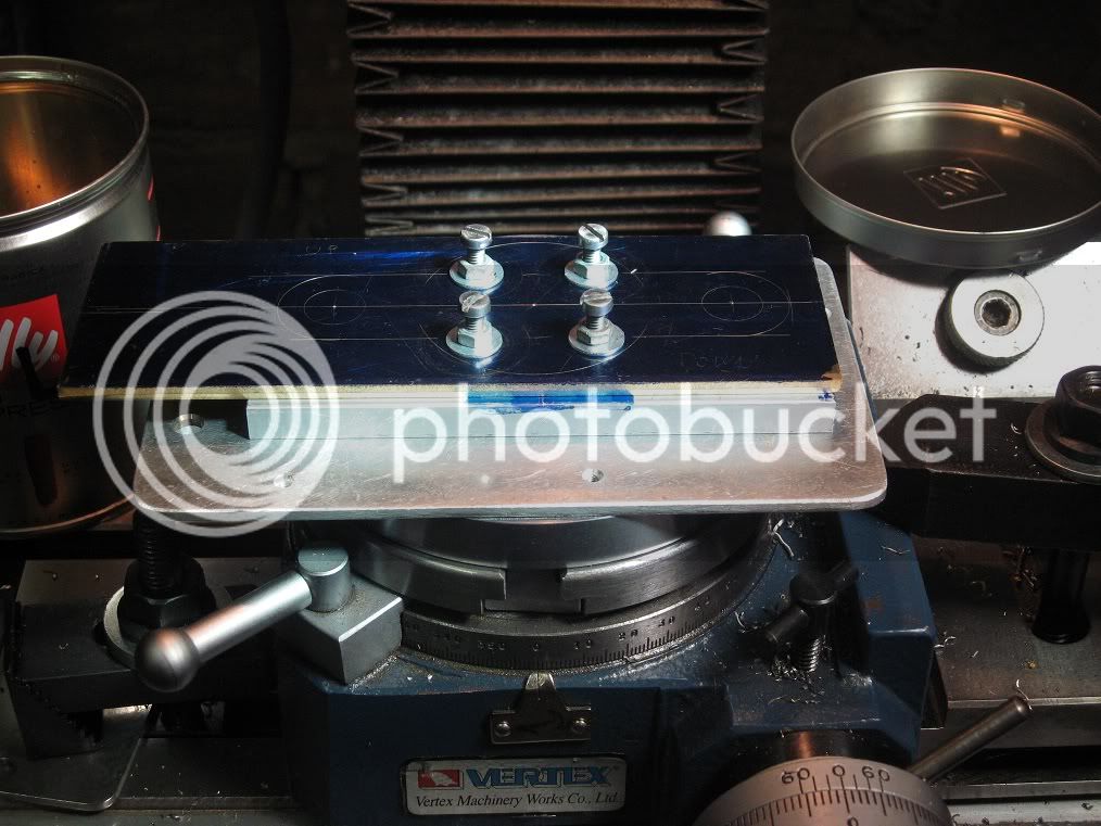
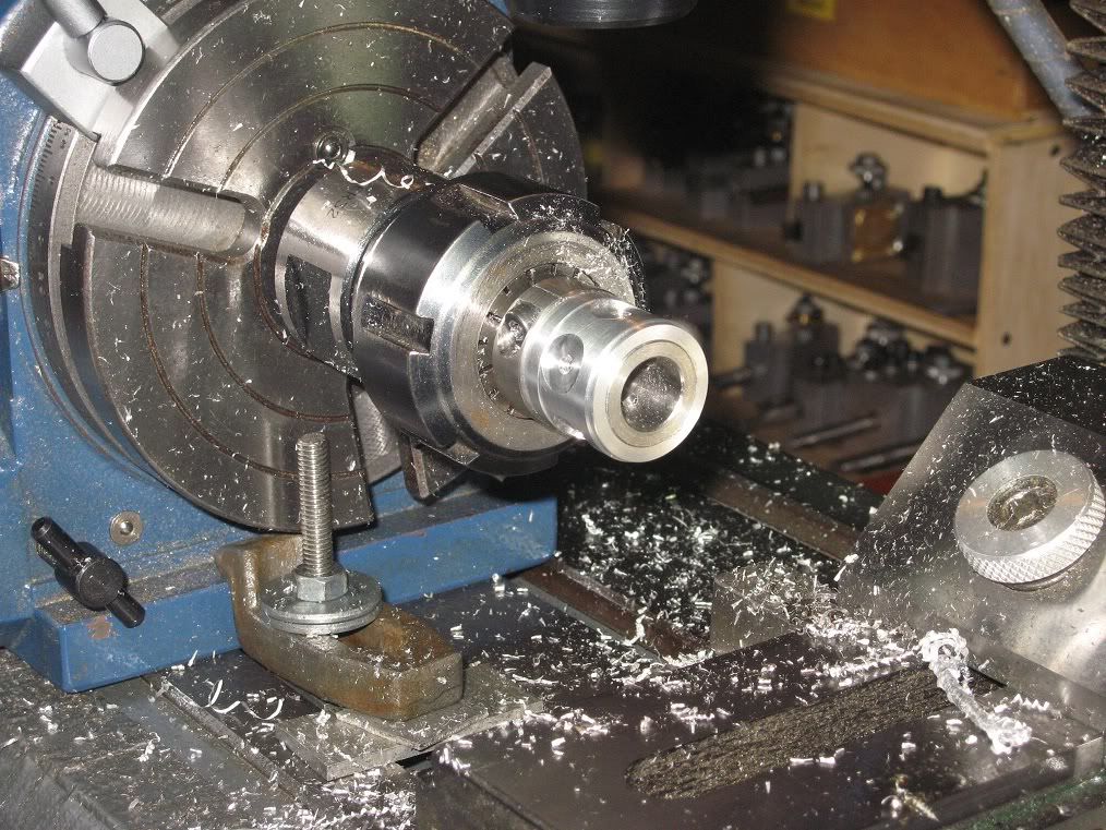
Still on the RT, to drill and countersinking the matching holes on the ring. That’s a 68mm Proxxon chuck I have mounted on a 20mm steel arbor to fit the largest collet of the ER32 series.


16Fw_IMG_0280.jpg


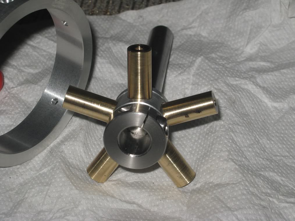
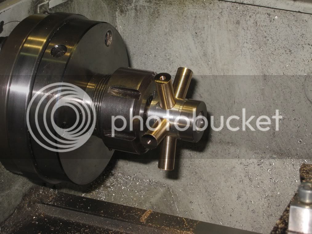
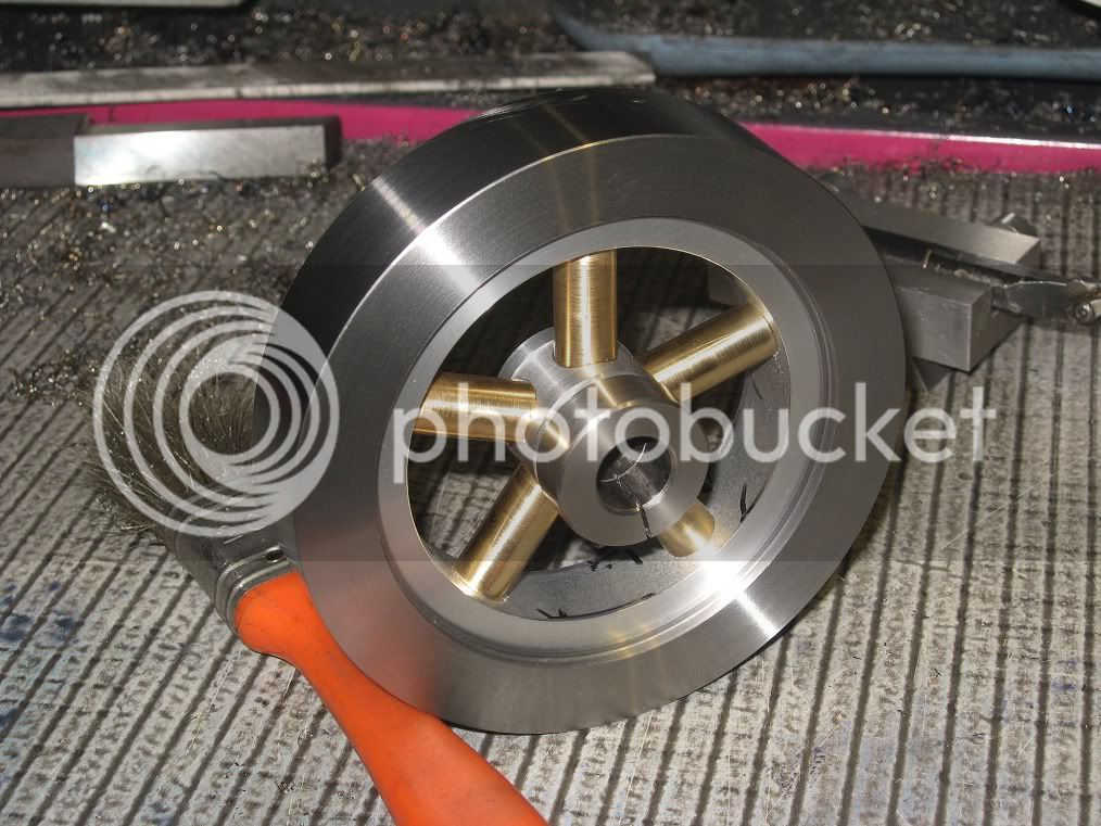
Having the five brass spokes turned, drilled and tapped M3, I cut portions of five of the ugliest M3 screws I had and used them as studs, with a bit of loctite to prevent unwanted unscrewing during the

next operation.

17Fw_IMG_0282.jpg


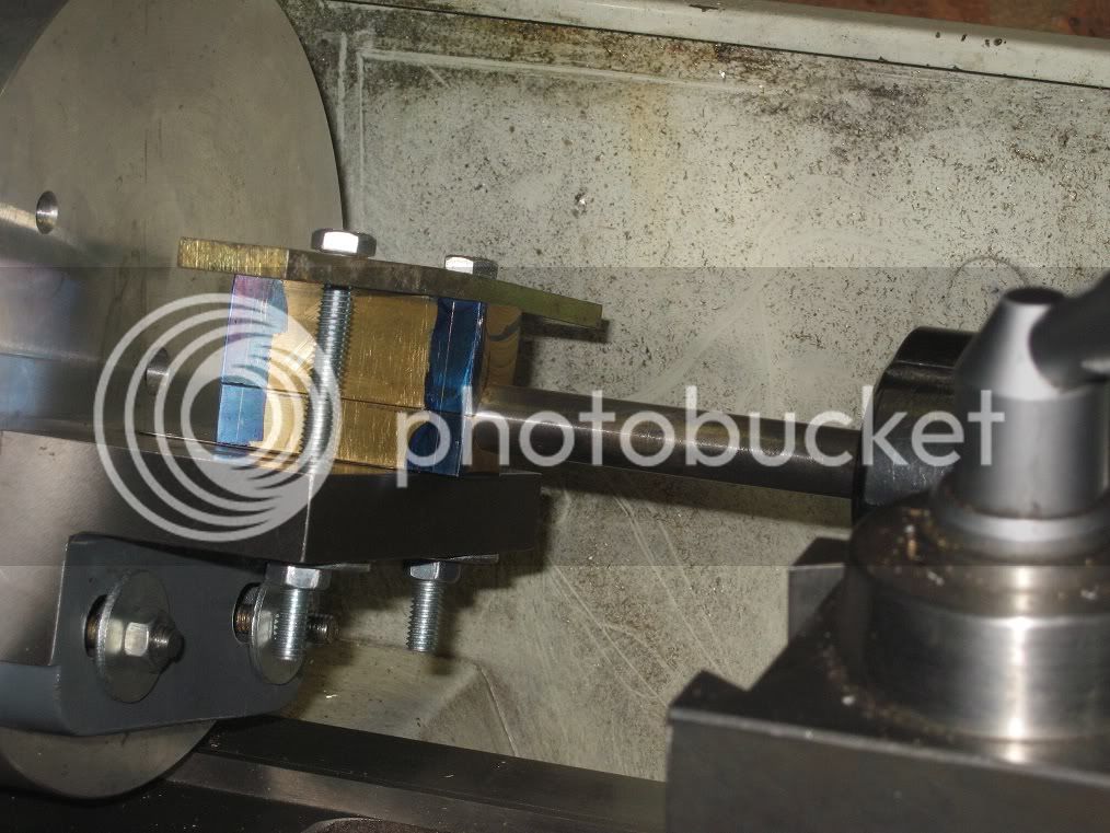
of turning them to a nice fit into the rim.

17Fw_IMG_0284.jpg


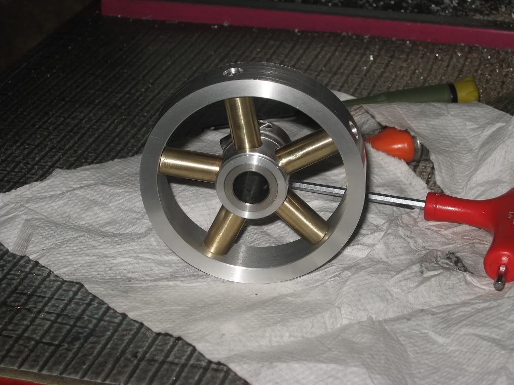
Again a bit of loctite on five cs screws and the rim is ready for the final truing on the lathe.

17Fw_IMG_0285.jpg


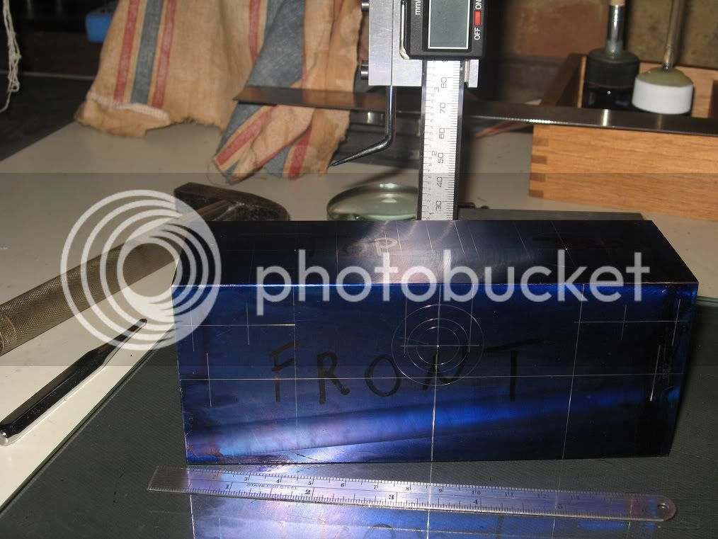
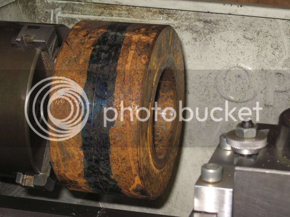
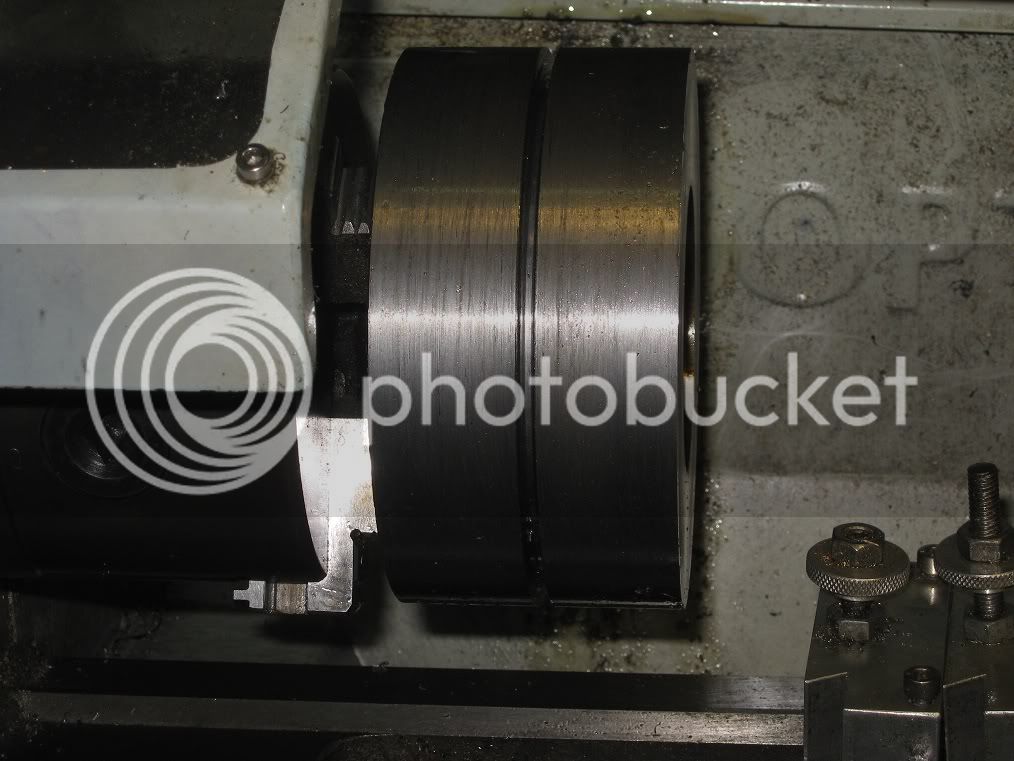
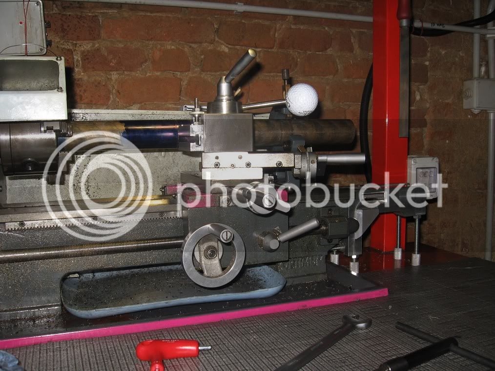
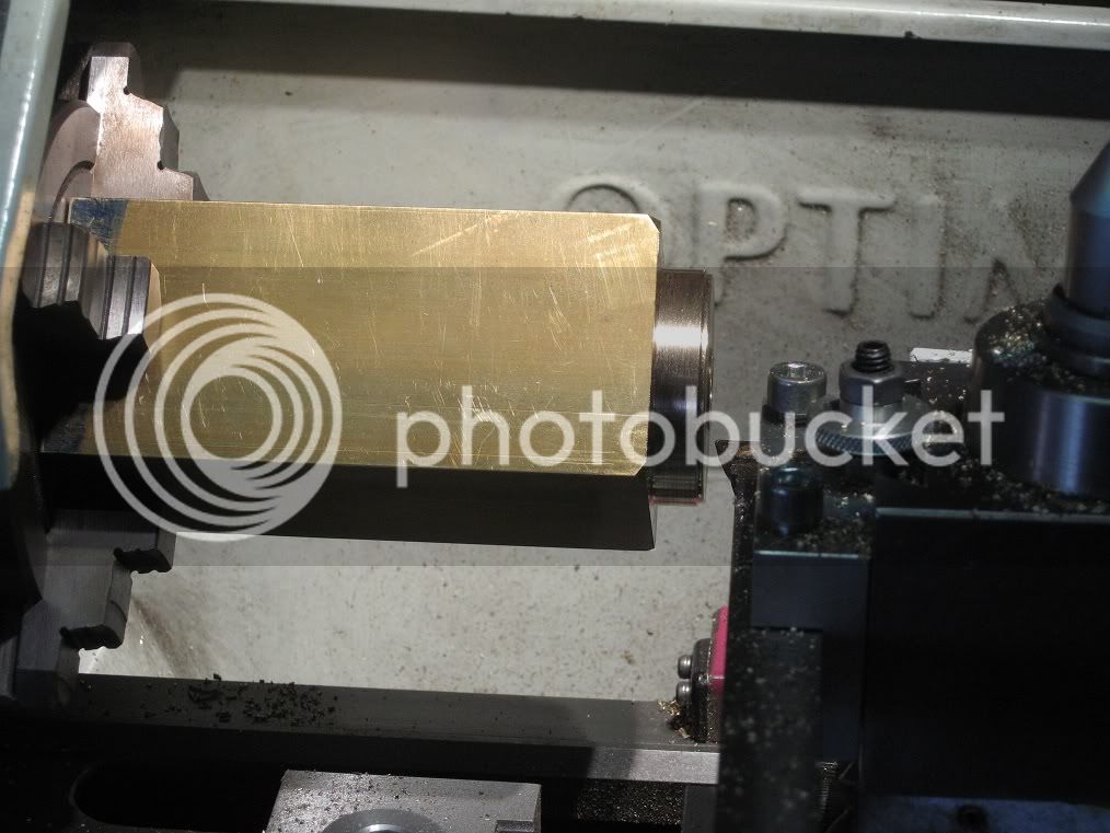
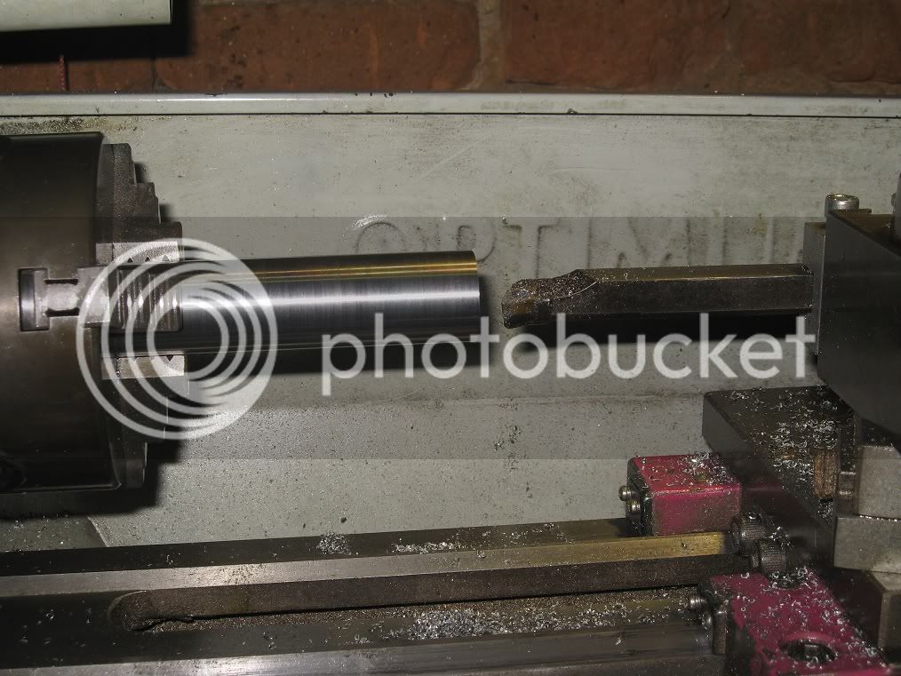
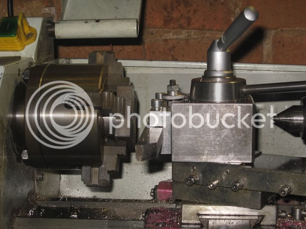
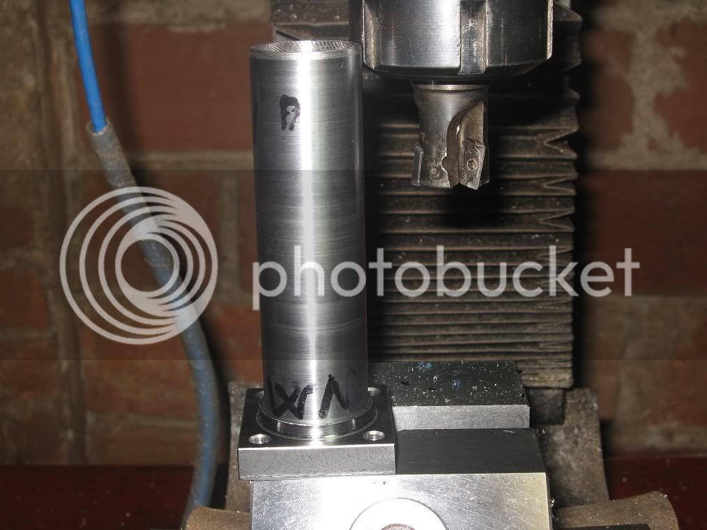
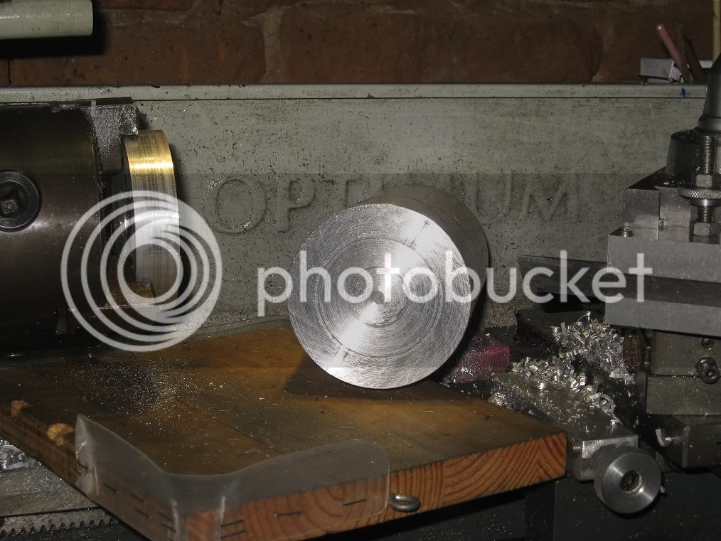
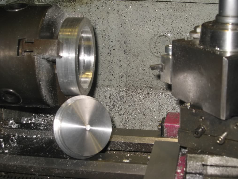
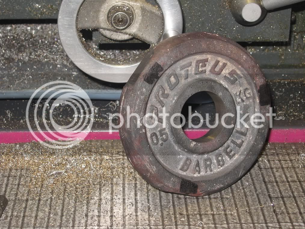
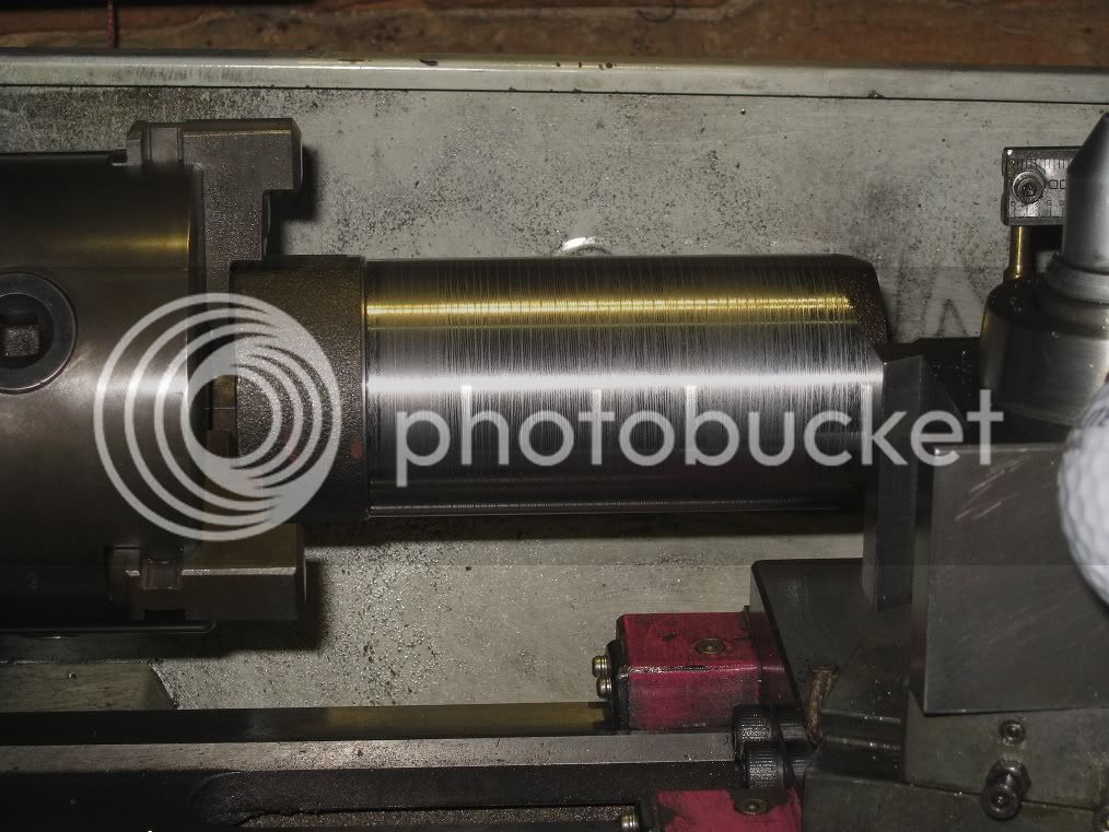
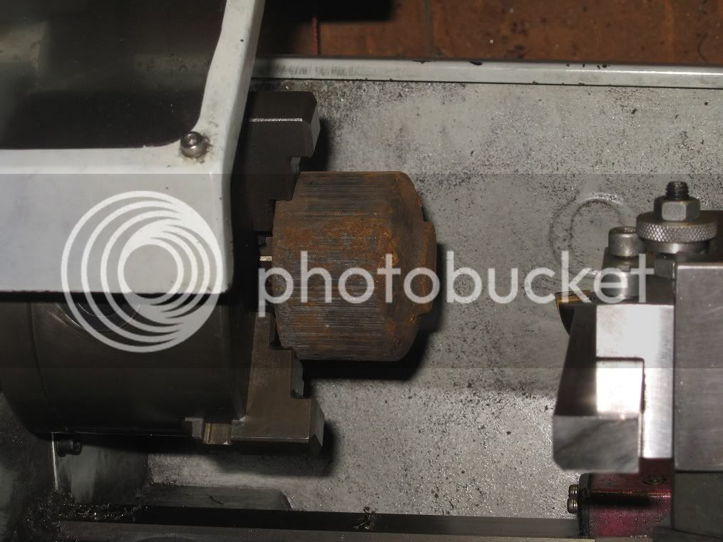
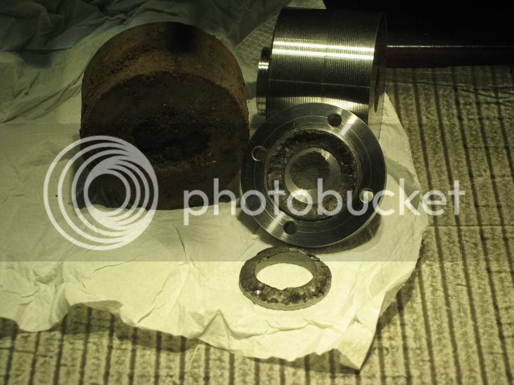
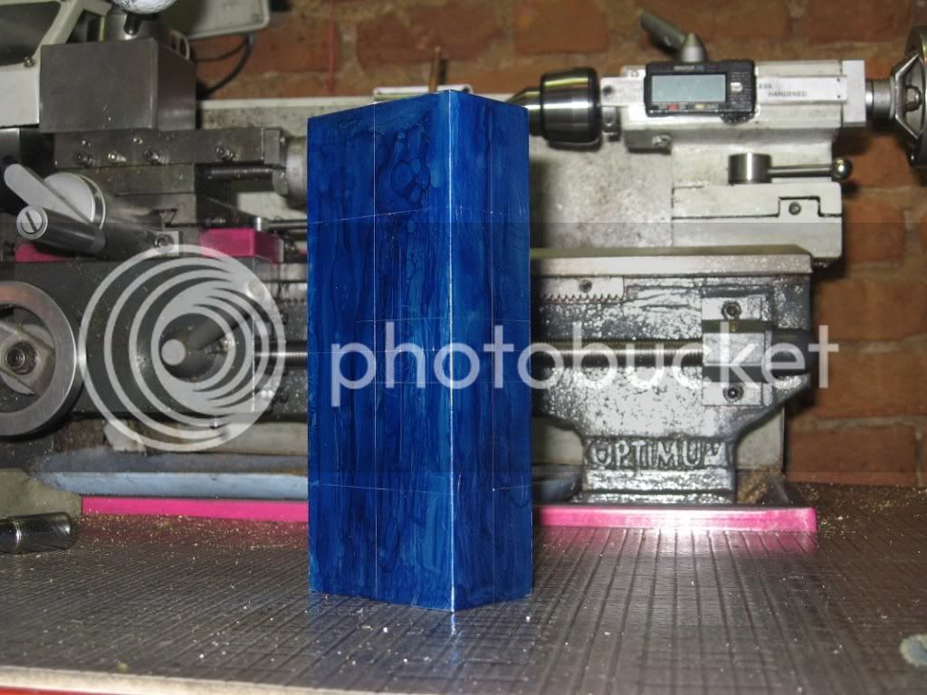
This barbell weight had resisted any previous attempt of machining: it simply ate the HSS bits like they were butter, and chewed the edges of the carbide tipped ones.
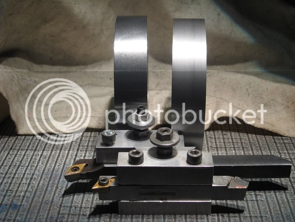
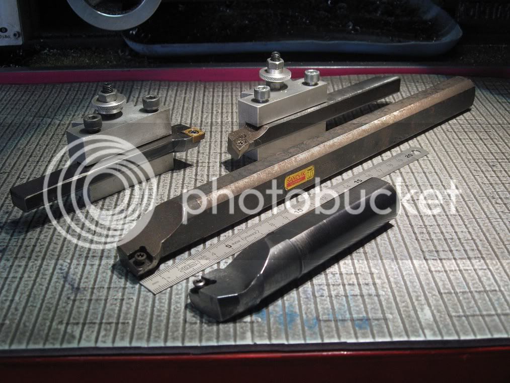
Now I’ve got some insert holders to try it with.
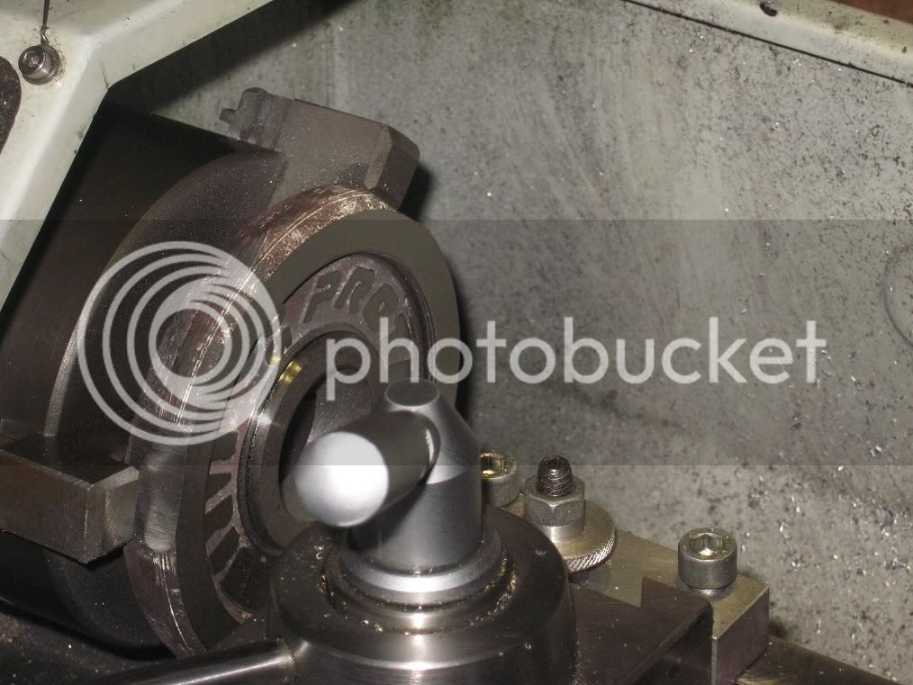
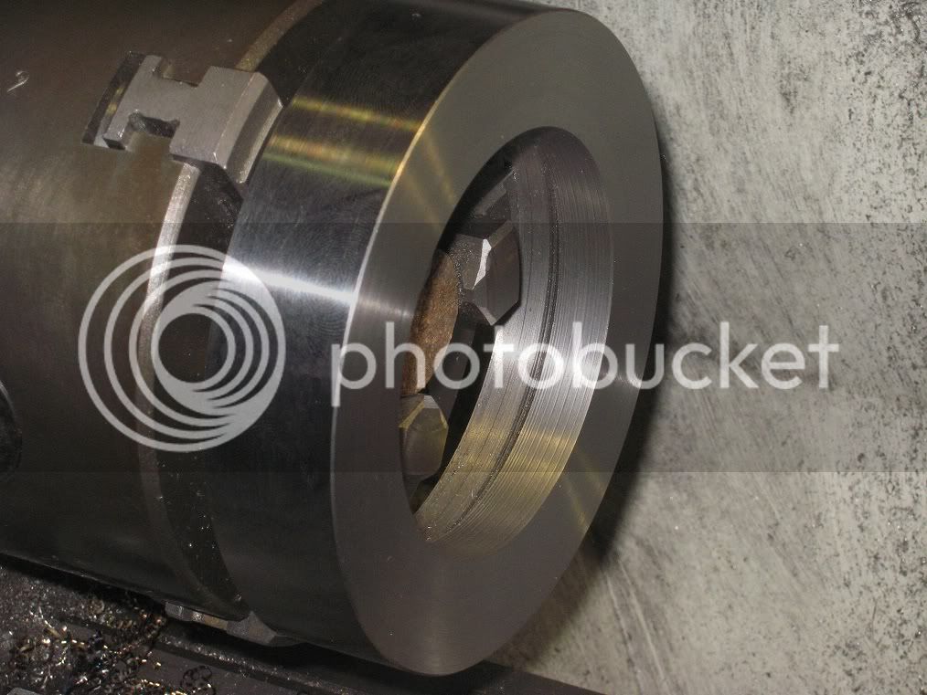
First of all, I ground three notches on the circumference, for a better fit into the chuck: I really do not want the thing to chase me through the shop.


18Fw_IMG_0291.jpg


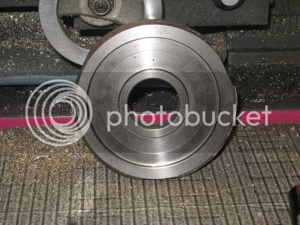
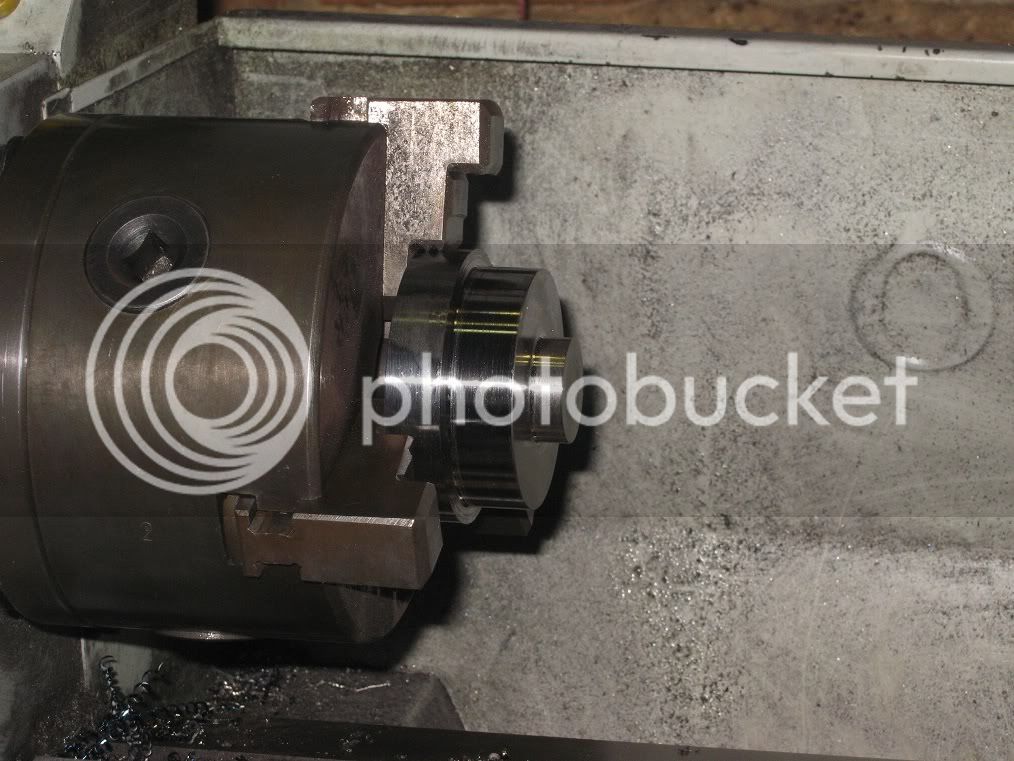
Guess what? They are working!

19Fw_IMG_0290.jpg


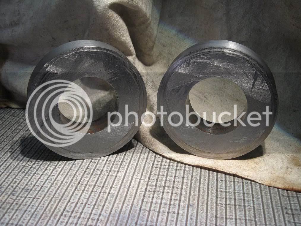
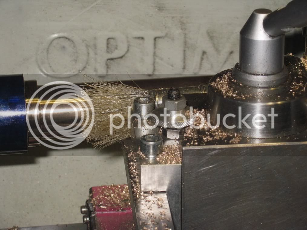
First side done. The material is really poor, rather rips instead of cutting. And some blow holes are appearing…


19Fw_IMG_0292.jpg


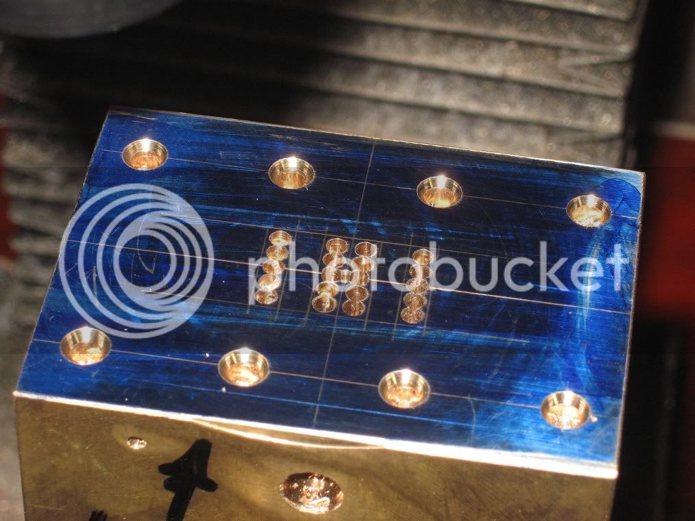
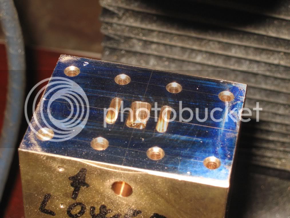
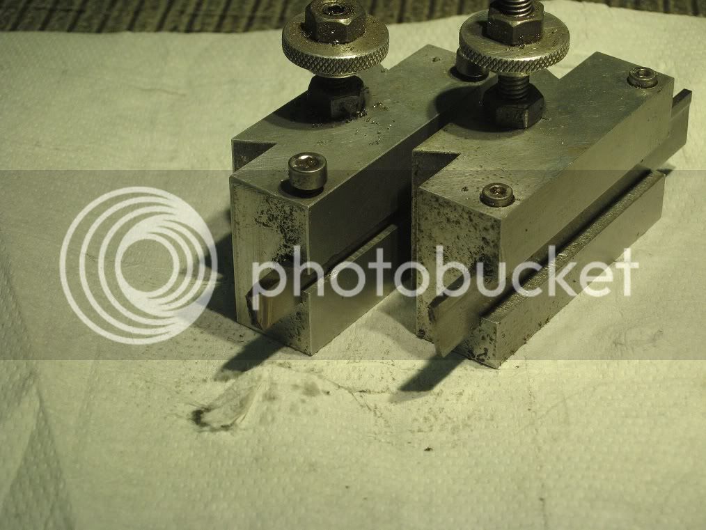
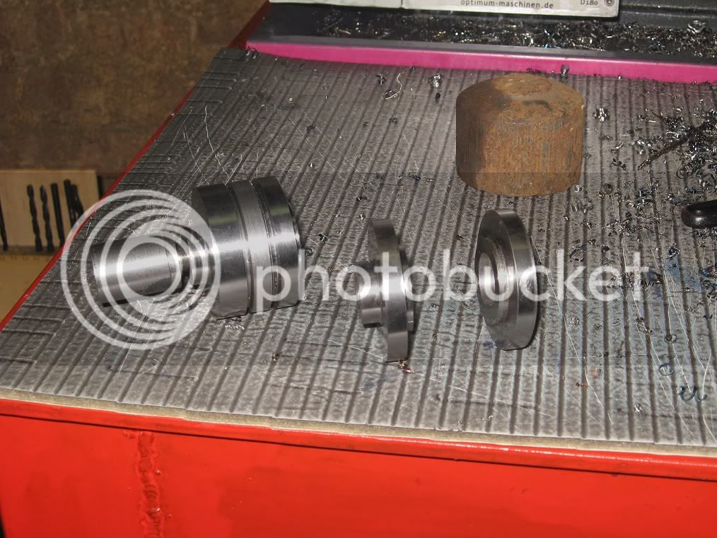
An old picture of them tools, the lower two shown before I milled out the shank in excess.

19FW_IMG_0293a.jpg


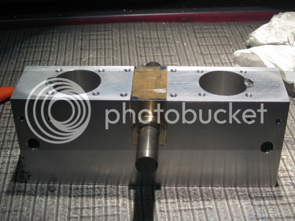
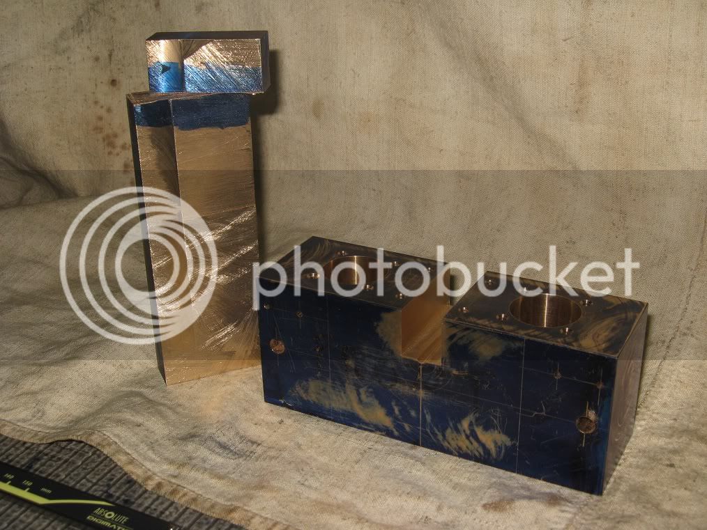
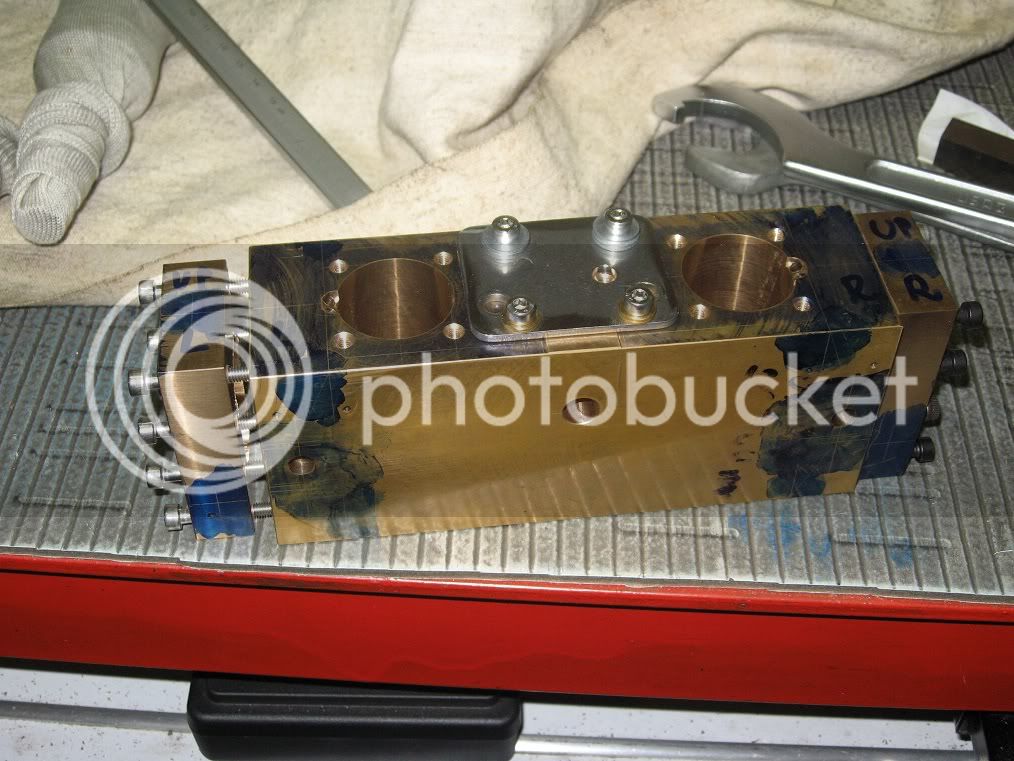
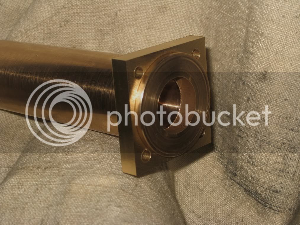
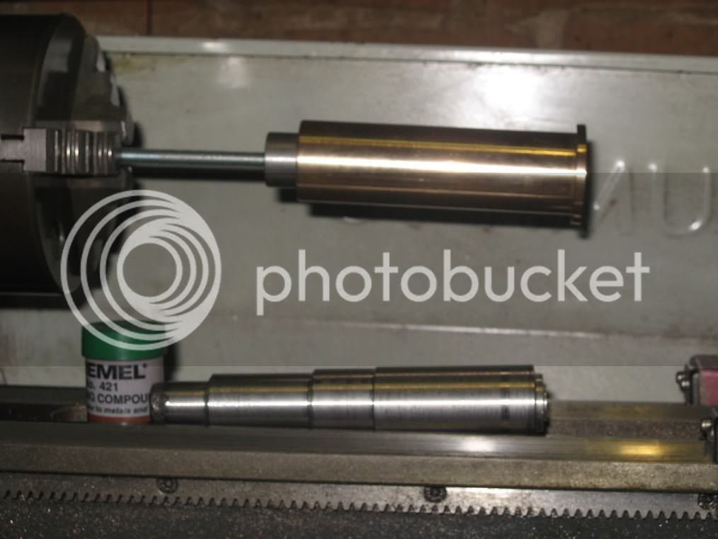
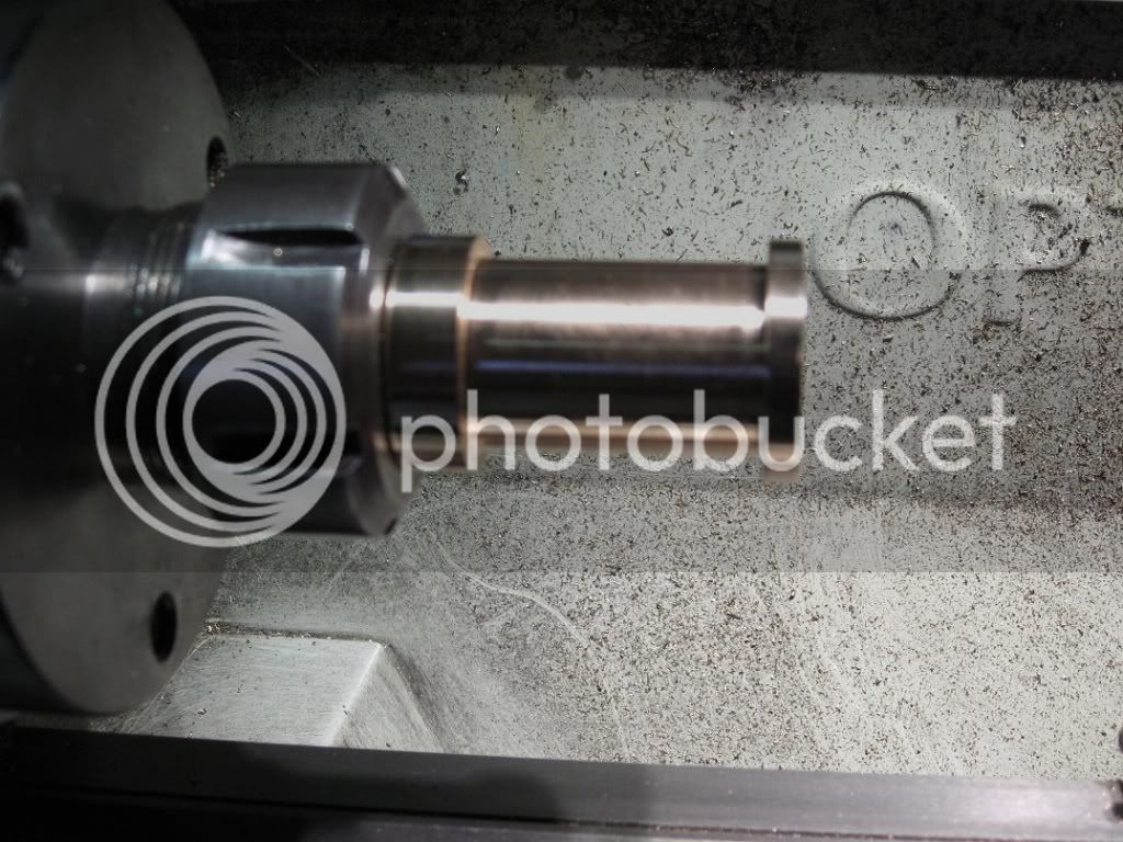
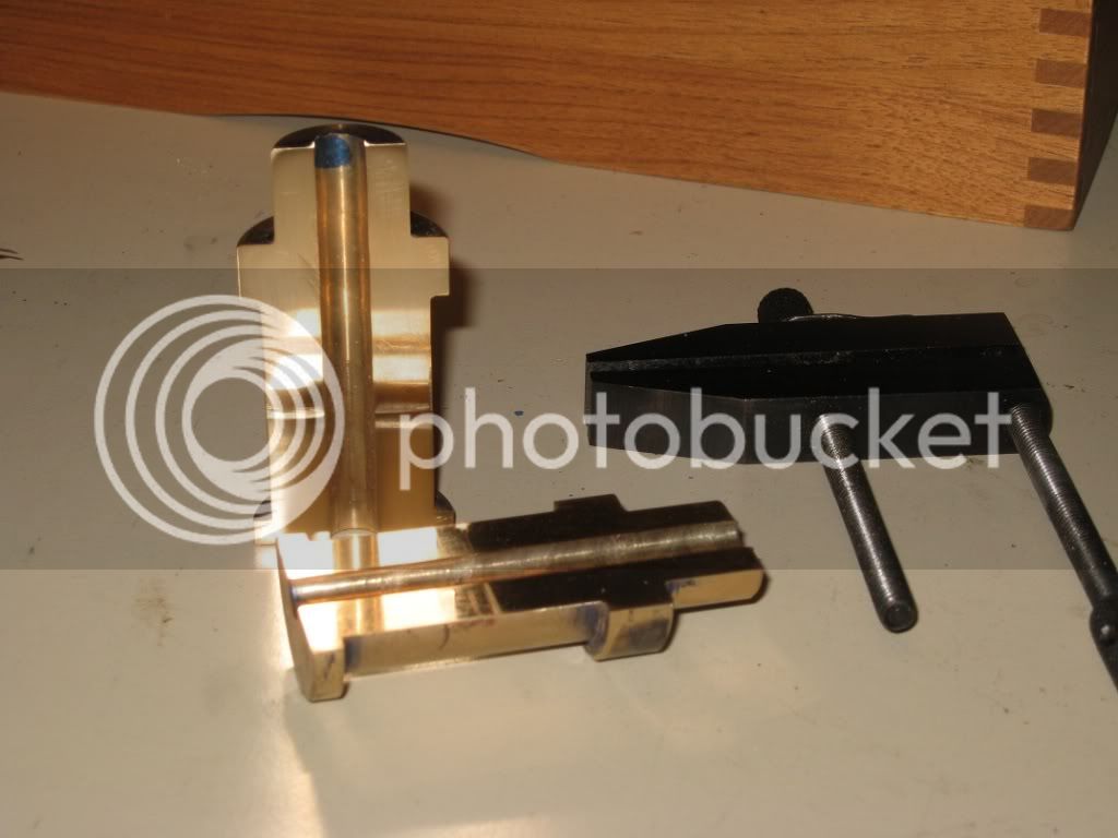
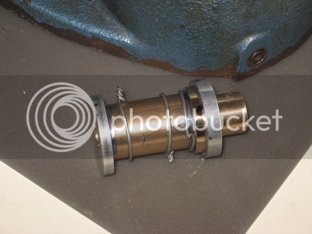
The hub, Chucks design again. (If it were not for cutting the half way slit 90deg wrong, :- ( - It still works, anyway - )

19Fw_IMG_0296.jpg


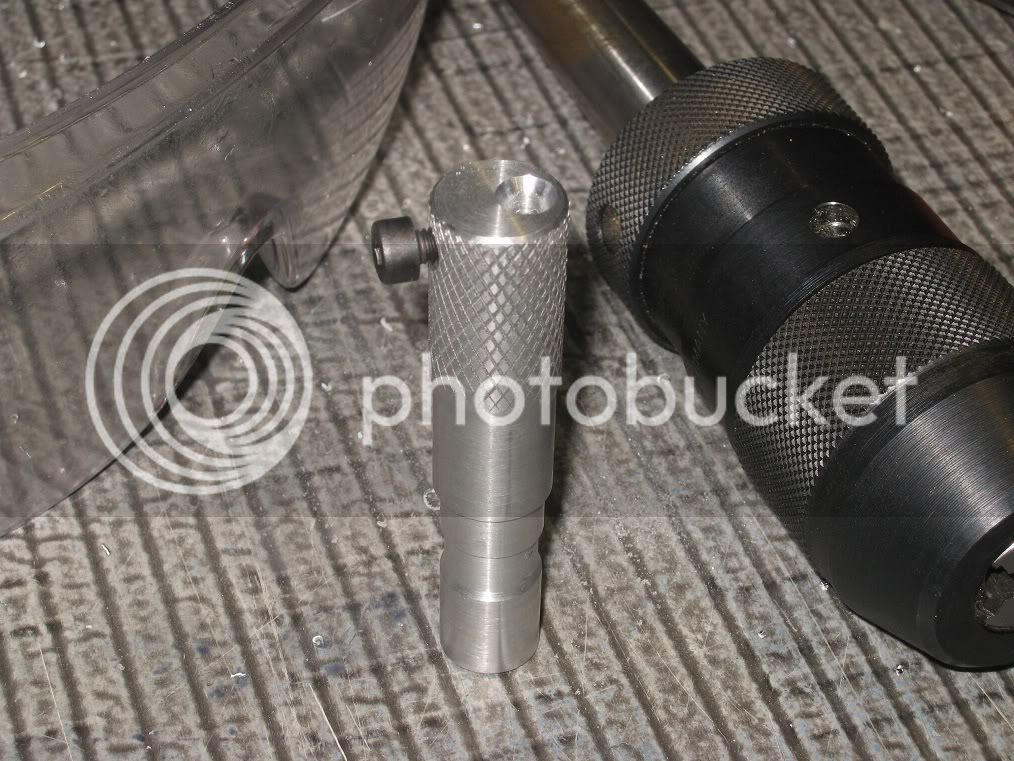
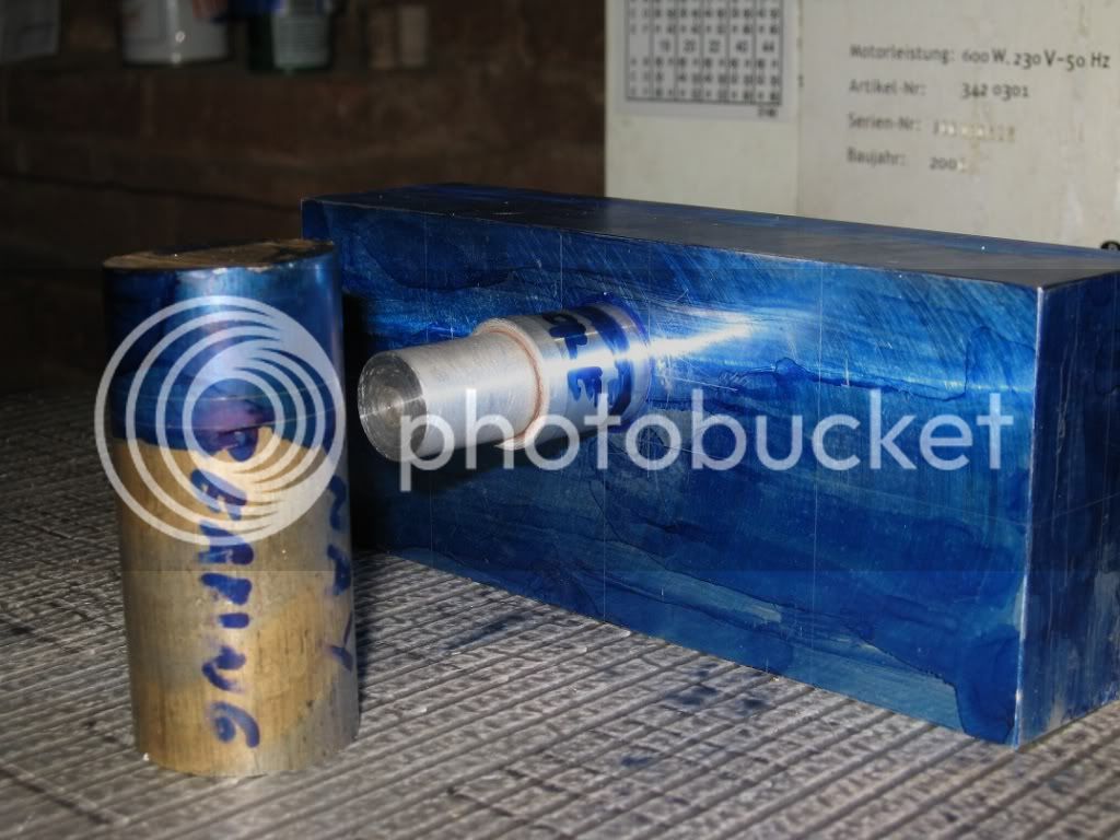
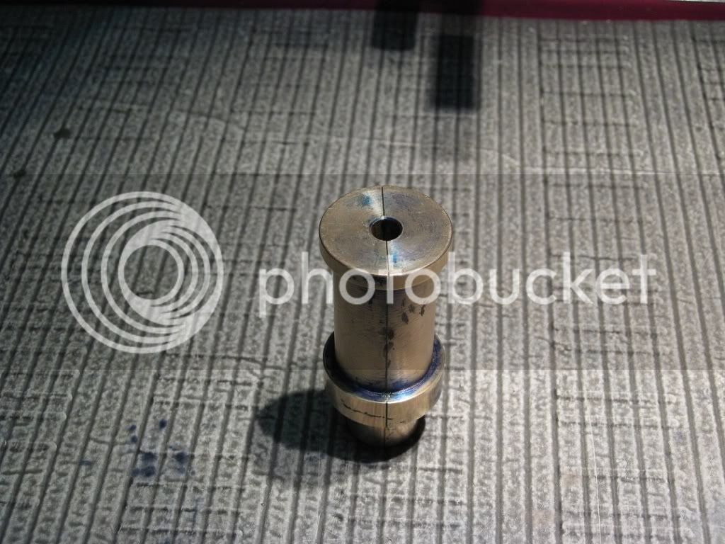
And the sleeve, before press fitting.


19Fw_IMG_0298.jpg


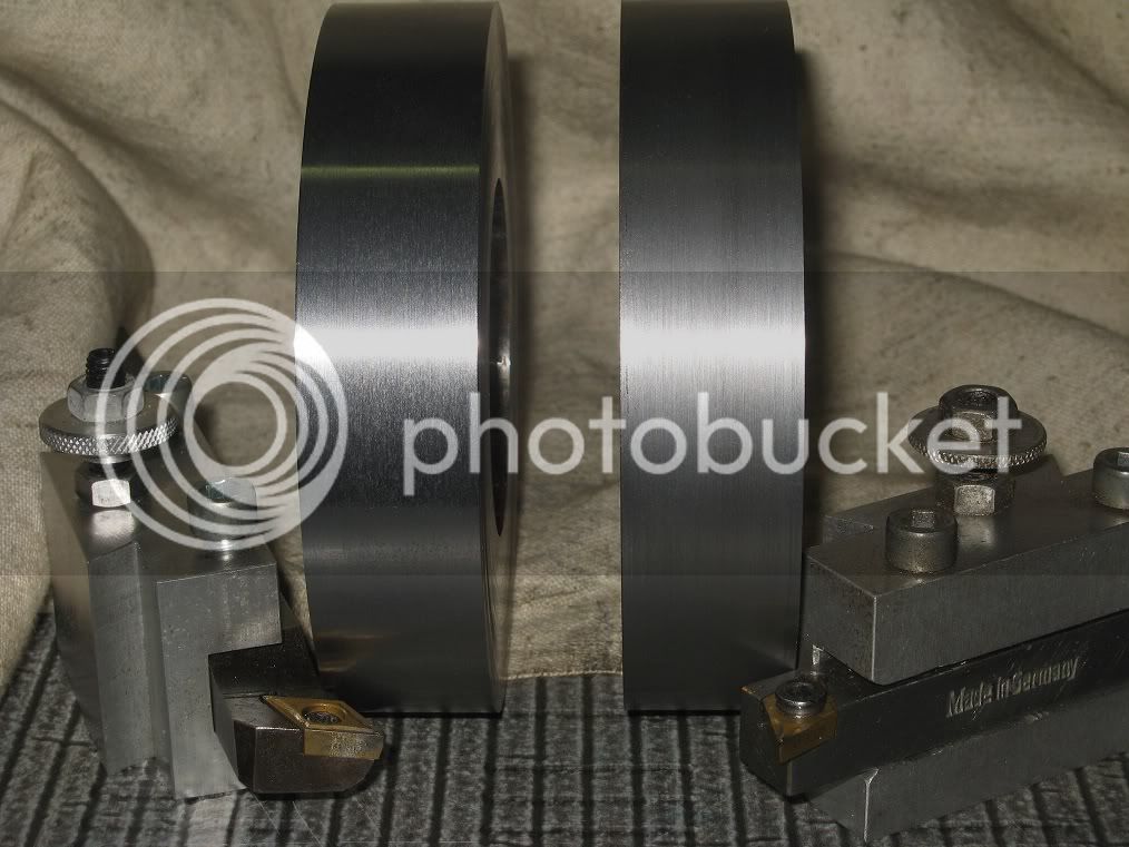
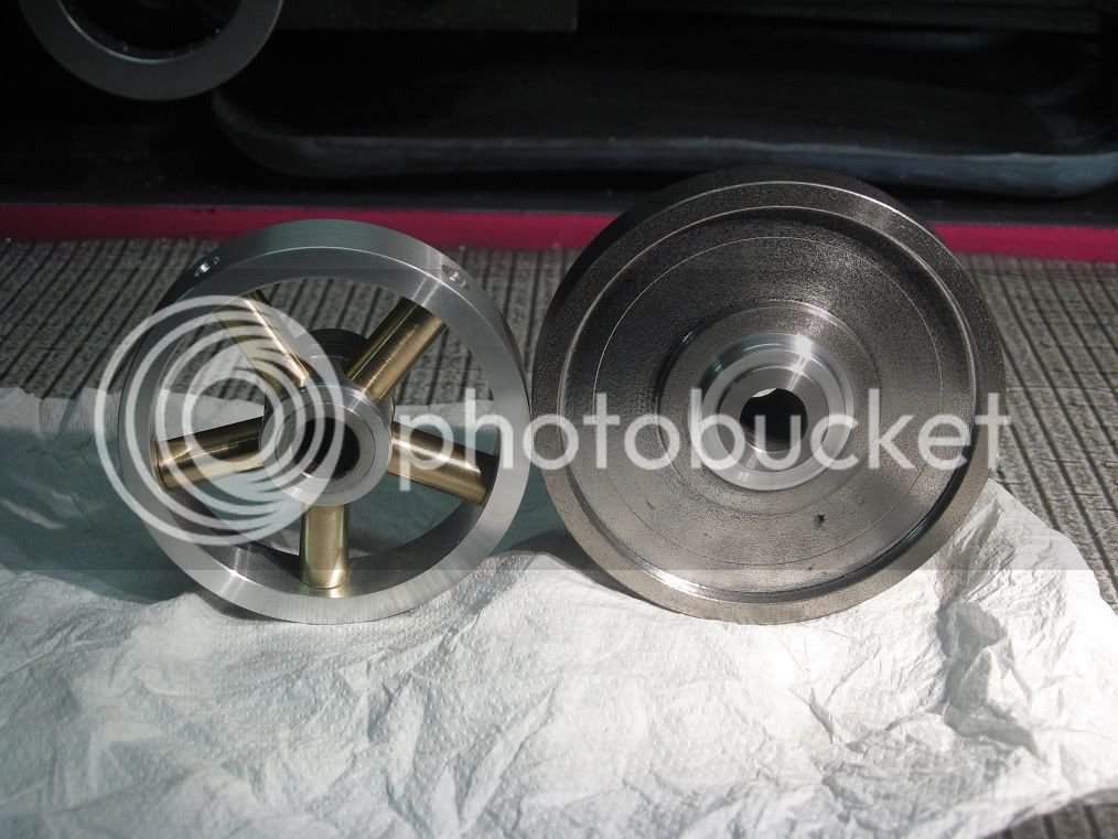
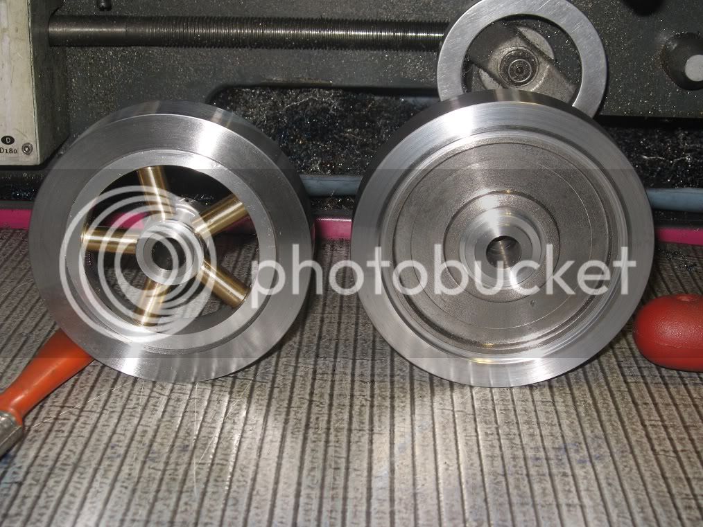
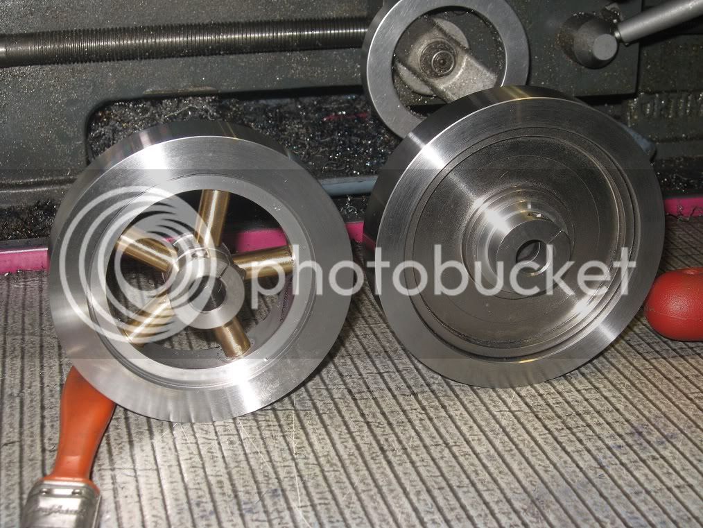
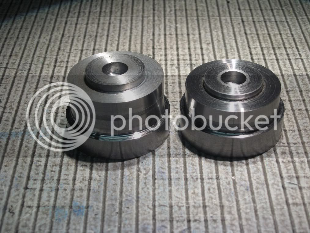
The two, yet unfinished flywheels, waiting patiently for their tyres.


19Fw_IMG_0299.jpg


The tyre problems

When the external jaw #3 dropped on the lathe bed, I knew for sure I could not hold a 105mm ring into my 100mm chuck. Not a 100mm ring, too: the limit being somewhere around 90, I discovered later.

Fonly I had some soft jaws!
The wiser option would have been fitting the thingy to the faceplate, for boring: but I really hate swapping workholding tools on the lathe, though it rarely takes more than a minute.
Went for some creative machining, instead.

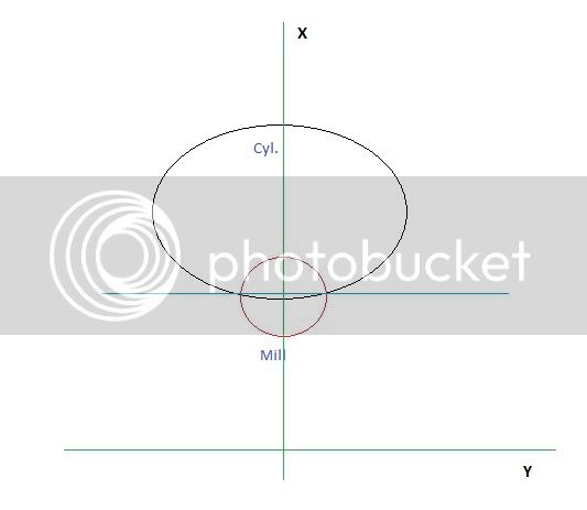
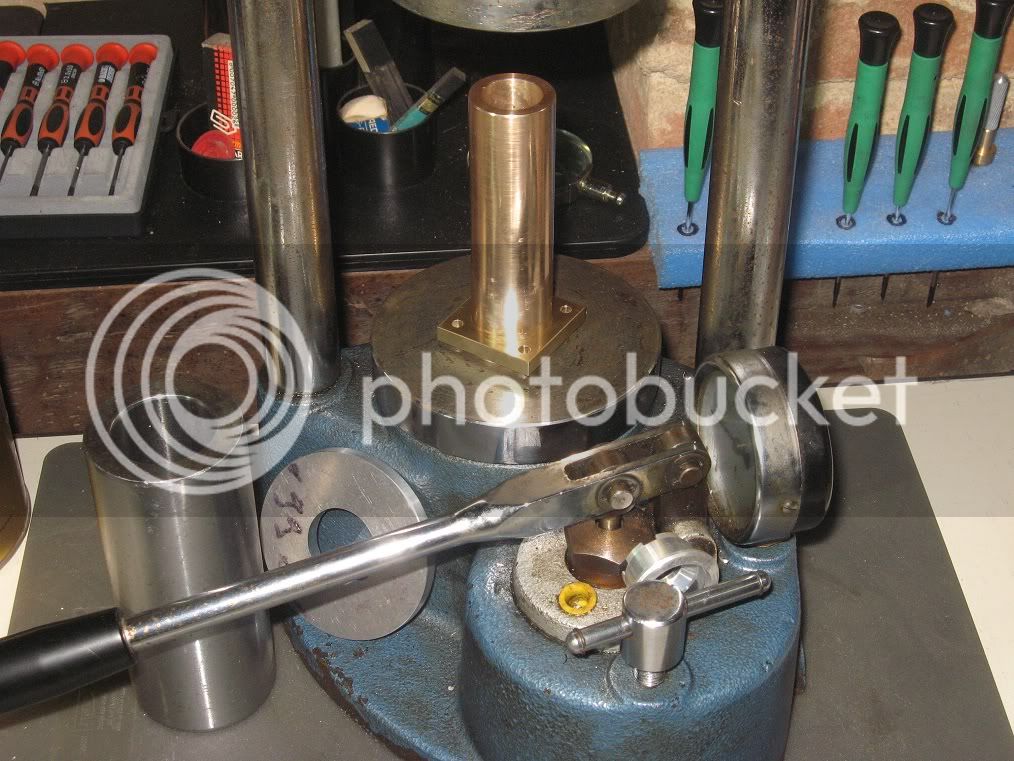
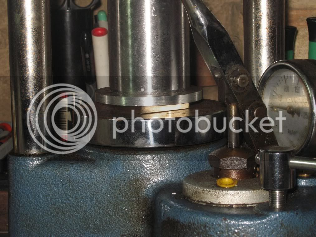
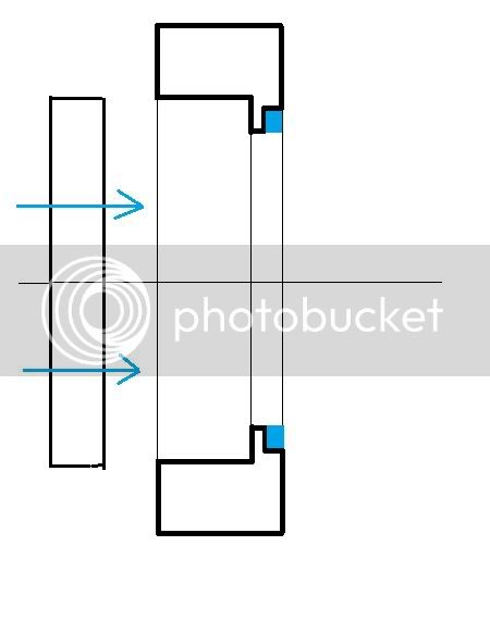
The ring was grabbed with the internal jaws and bored as deep as possible to a diameter 2mm shorter than the already completed part, with the exception of the initial 2.5mm that were enlarged to the

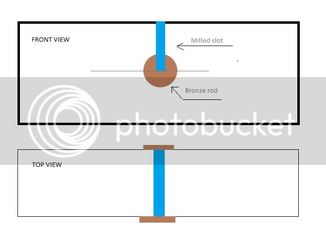
final diameter. Then it was reversed into the chuck, grabbed by the inside jaws on that step and to press fitting diameter, leaving about 1mm on the bottom to act as a stop for the press.

19Fw_IMG_0302.jpg


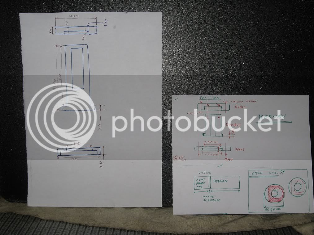
This might clarify the idea.

19Fw_IMG_0302_drawing.jpg


19Fw_IMG_0308.jpg


19Fw_IMG_0310.jpg


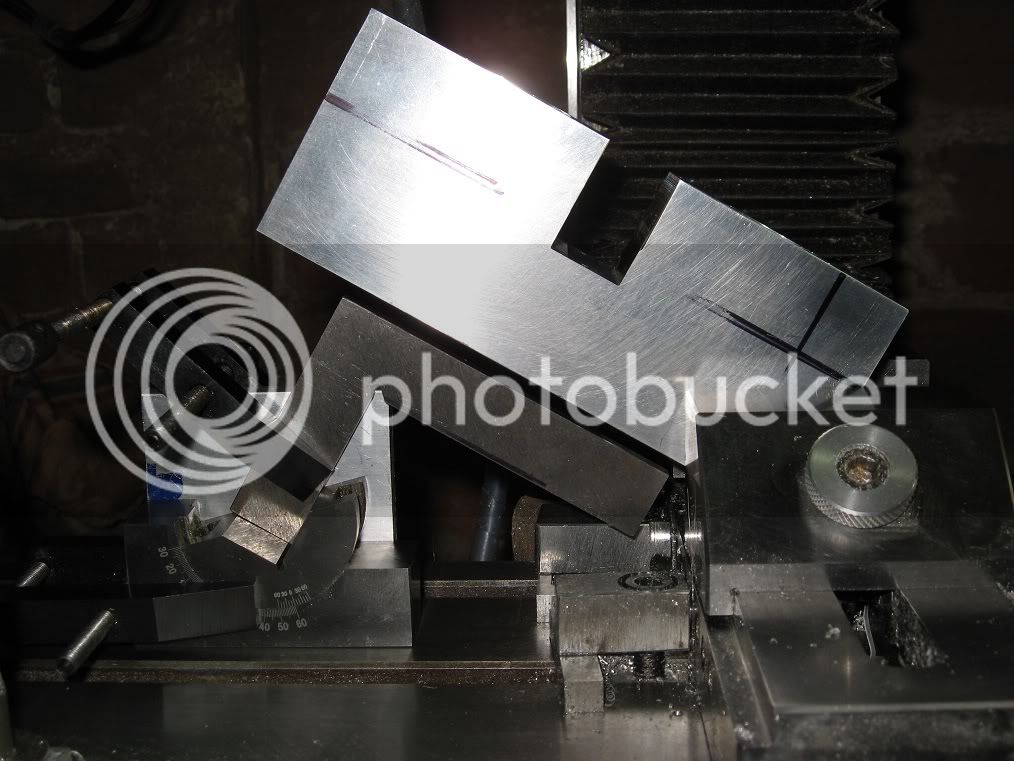
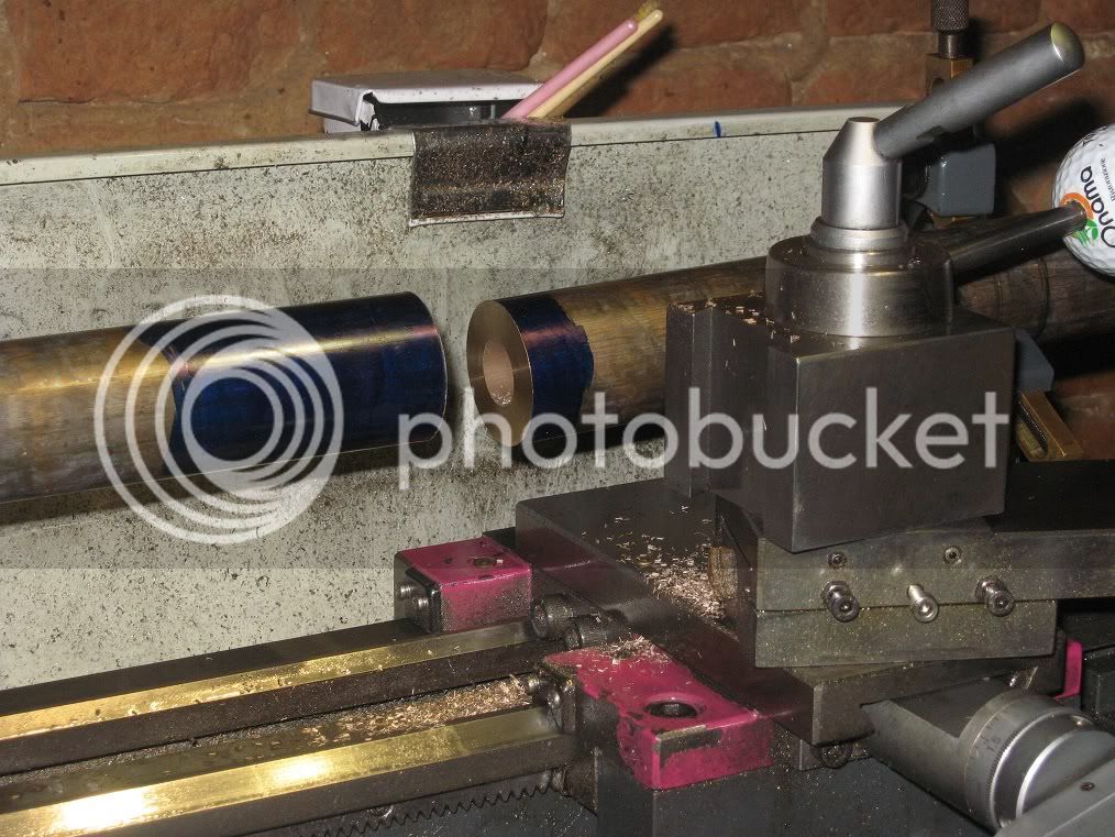
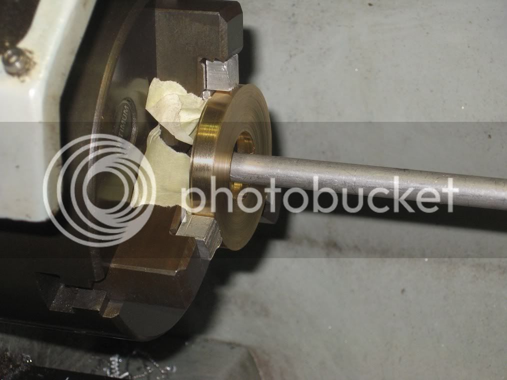
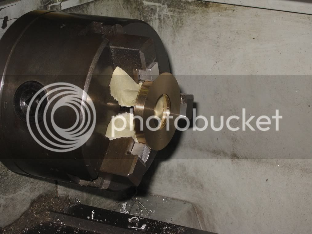
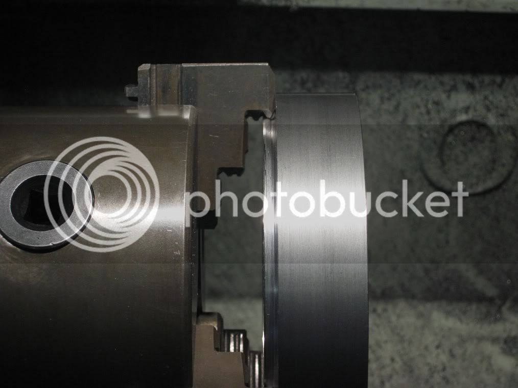
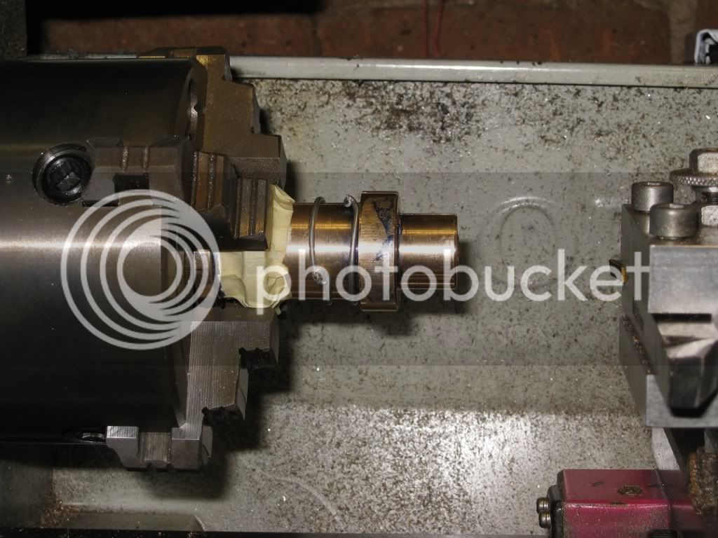
On the second tyre, I took a different approach: having the ring chucked by the internal jaws, I machined a small portion to about 90mm, with the tool at an angle so to have the inner diameter shorter

than the outer: that should ensure it won’t escape from the jaws.

19Fw_IMG_0314.jpg


A bit of paper tape stopped short chips from being thrown directly at me through the space amont chuck and workpiece.


19Fw_IMG_0315.jpg


Here’s the two flywheels: when I mounted them on a mandrel for the final truing, I could get mirror finish on the external surface and the ugliest chatter when cutting on the sides, though the mandrel I

used was rather stiff (a 12mm HSS bar)


19Fw_IMG_0317.jpg


19Fw_IMG_0319.jpg


I suppose they will go on the faceplate, someday. ;D


Marcello
 

Your fly wheels look great! and heavy duty too.

 
Cylinder Heads

This steel rod gave me a few problems ending with burning the motor brushes.
Finish was ugly, anyway, whatever tool and speed I was using with it, unless I took deep cuts and cranked like hell to keep the feed rate well above the 0.1mm turn of my lathe.
When I replaced the lathe motor, I realized there were no reasons to use a material so nasty to make some low stressed parts as the cylinder heads.

20_IMG_0331.jpg


Went to the metal recycler, instead, and bought myself 18kg of these, for the price of 4euros and a coupla baskests of swarfs.

20_IMG_0332.jpg


I removed most of the surface scale on a couple of them, using a well-worn insert, then moved to a much better one to continue the machining.

Here, I’m making one of the upper heads: a few mistakes will become evident soon.

20_IMG_0333.jpg


a) the smaller diameter was made ¼” thick, as per specifications. Had I left it much longer, things would have been easier, later.
In fact, I had no ready made means of holding it for parting, the upper step of the external jaws being too large, the lower step too deep… tried to put it into a collet, but the thingy went flying through the shop.
In the end, I tapped it for the piston gland nut, machined a threaded mandrel and screwed the soon to be parted heads on it. (See next picture)

b) The chuck end of the workpiece had a blind hole in it, much like the hole the .0438 hole specified in the drawings for the lower head. What a luck, I will make use of that!!!
Wrong! I should have faced it to remove all that area, where I will find loads of cracks and blows (well visible into the items shown three pictures below)

Upper and lower heads, and the threaded mandrel I made to hold them to part them off.

20_IMG_0337.jpg


A small fixture to drill the bolt circle on the heads: I zeroed the DRO, bored the central hole to size, drilled four holes at coordinates, and repeated the last operation for all the heads.
(Gotta do something with the rust on that boring bar: doesn’t show well in pictures).

20_IMG_0338.jpg


20_IMG_0340.jpg


Marcello

 
Cylinders Heads (again…)

Tapping the holes for the feet into the lower heads was a real pain!

All my M4 taps were dull (time to buy myself some new ones) and the only way I could tap them holes was in careful steps: one thread with the taper tap, then with the second and the plug. Back with the taper, second, ..., …, and again, and again…

That steel was unexpectedly hard.
On the LAST hole (there were four) I lightly bottomed the tap: very - very - lightly.

Here’s the results:


21_IMG_0341.jpg


If it were not for some thin metal layer I had left around the bore, the whole area below the ring was a continuous blow!

There might have been reasons they were sent to the scrapyard.


The new, still unparted, heads (below): I had the material carefully faced till it was all clean and bright, before.


21_IMG_0344.jpg


As for the old ones, I’ve not yet reached a decision about their final destination.


Marcello
 
I have never seen a piece of stock come apart like that from a bottom tap!....clearly it is hard!....and probably cracked, though from what I can see in the photo, it looks like a brittle tensile break.......

Must be harder than woodpecker lips! ;D


YUCK!....find some nice free machining stainless Marcello!... :)


Dave
 

Latest posts

Back
Top