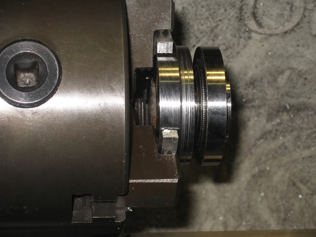
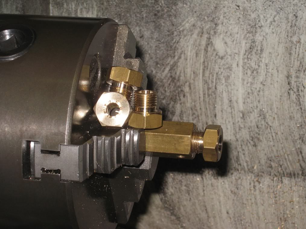
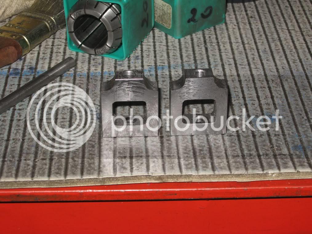
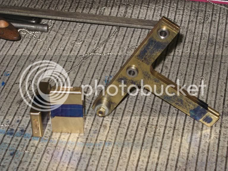
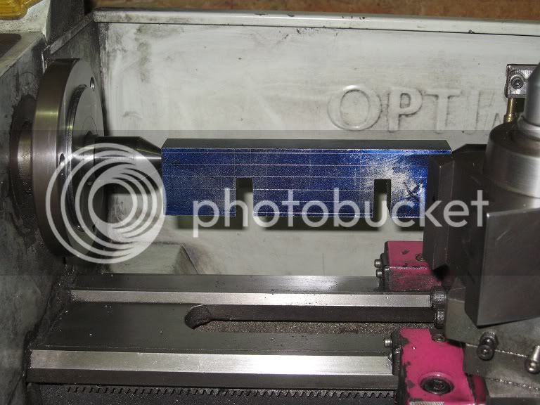
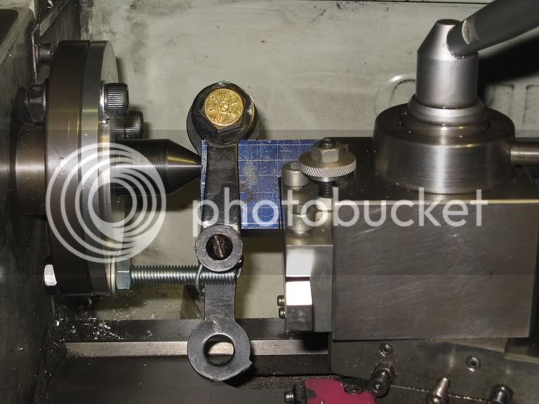
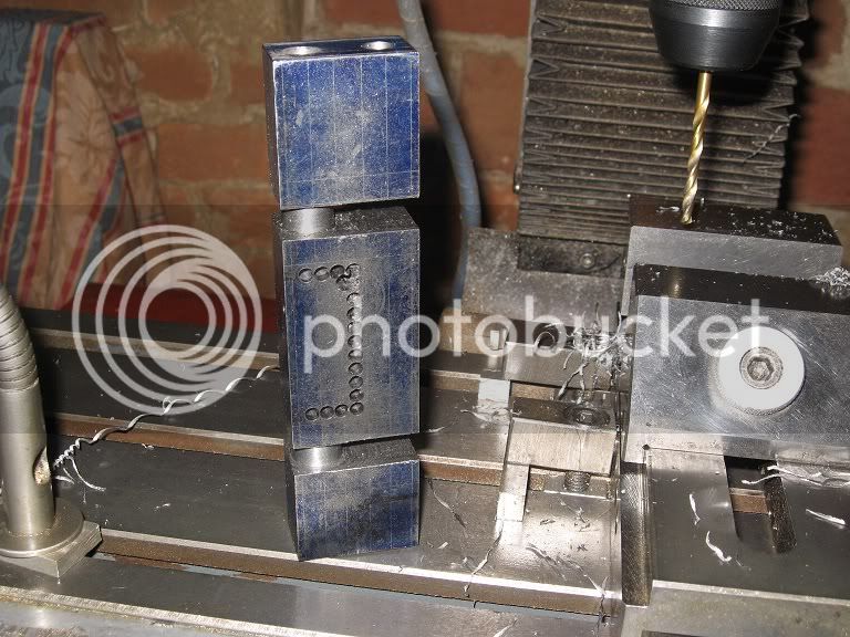
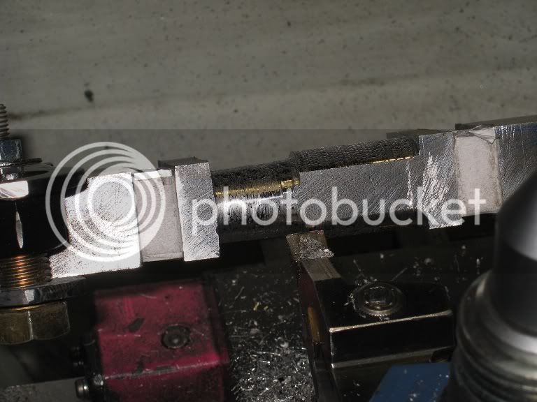
Bernay build - MZT

Home Model Engine Machinist Forum

Help Support Home Model Engine Machinist Forum:

This site may earn a commission from merchant affiliate links, including eBay, Amazon, and others.
Dave,

Yes, the whole area was cracked, but I did not imagine things were so bad int it, from the little lines I had sen into the bore.
I've attached an unresized (but cropped!) portion of the previous picture: the cracks should be more visible.
Marcello

21_IMG_0341-pt.JPG
 
Hi Marcello.sorry about little of topic!

you wrote"This steel rod gave me a few problems ending with burning the motor brushes."

is this motor construction weak??
what model do you have?
I am about to by lathe so nice to know.
Very interesting build by the way..inspiring :)
 
EL,

my next line was "...unless I took deep cuts and cranked like hell to keep the feed rate well above the 0.1mm turn of my lathe."
A bit more about it here -> http://www.homemodelenginemachinist.com/index.php?topic=15962.msg163199#msg163199
And then there were all those pictures about turning barbell weighs....
No, I don't think I can put any blame to that motor. Not after six or seven years of berserking.
The lathe is an Optimum D180x300: I'd buy another, especially if the new model were longer, larger ... ;D

Had some problems with the (same brand) BF20 mill motor, too: again, aint much sure I could put any blame to the motor itself, as I ran it continously, at maximum speed, in REVERSE, for an entire afternoon. And that was duriing the hot season, say about 35C in the shop.
As I understand it, those little motors with no independent cooling fans are not happy when run in reverse: a bit of care is in order.

Marcello


Pictures and more pictures... I love it!!!

Very nice job!

:bow:

Thanks for share with us!

Cheers,

Alexandre
 
Parting off one of the ‘new’ lower heads: had to get a bit creative into holding it into the chuck: no way to close the workpiece into the normal jaws, no way to part it if held into the lower step of the external jaws…
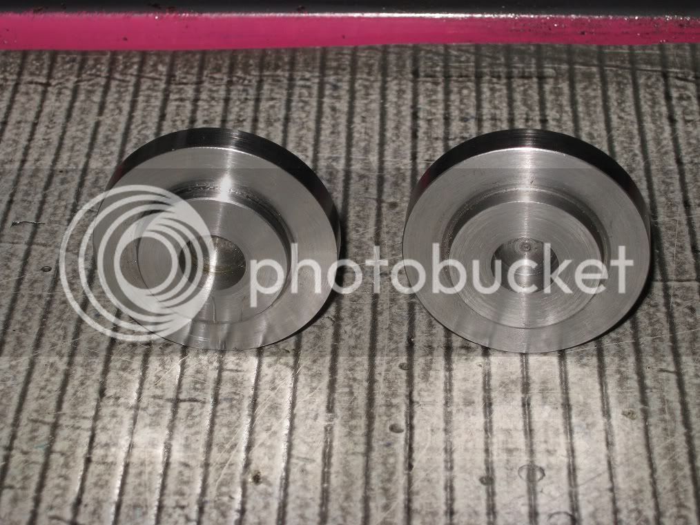
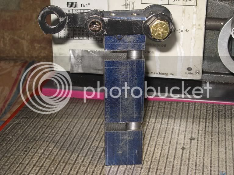
22_IMG_0373.jpg


Here’s the heads, before drilling the holes. (They’re finished, now – but for tapping the foot holes).

22_IMG_0374.jpg


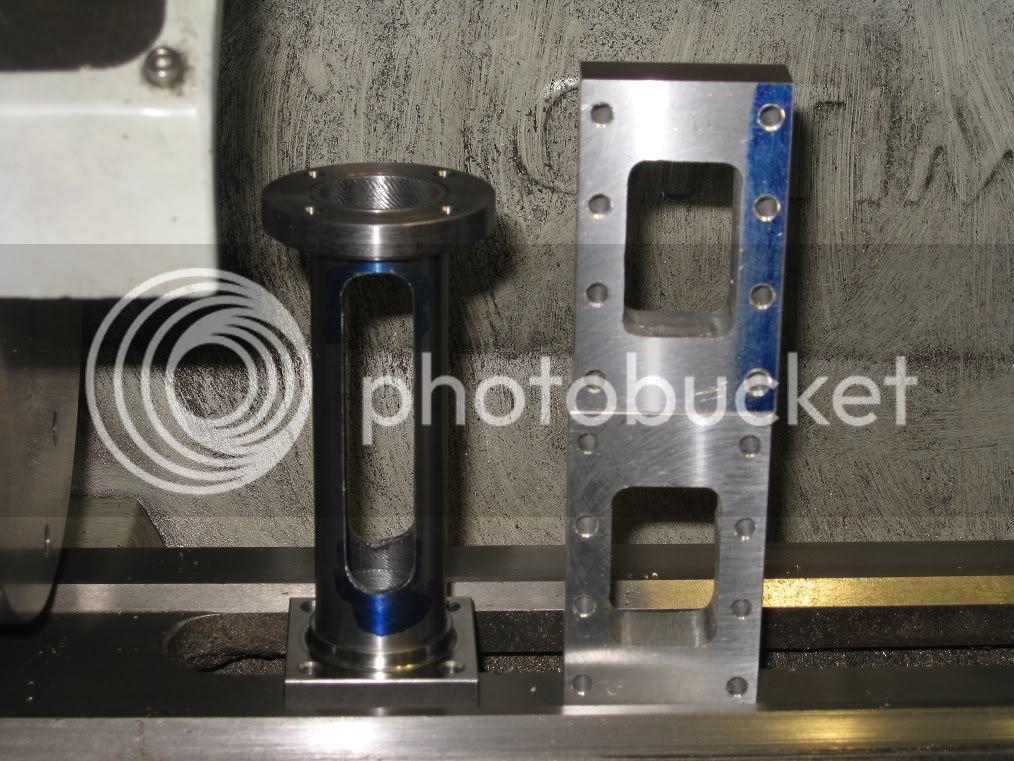
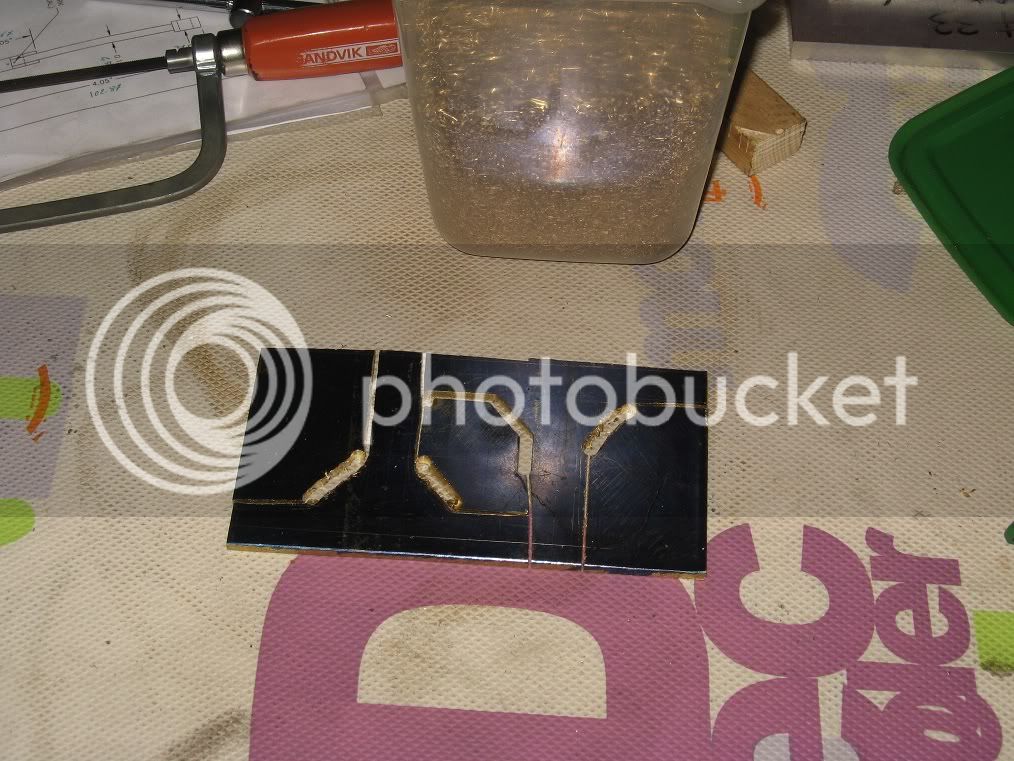
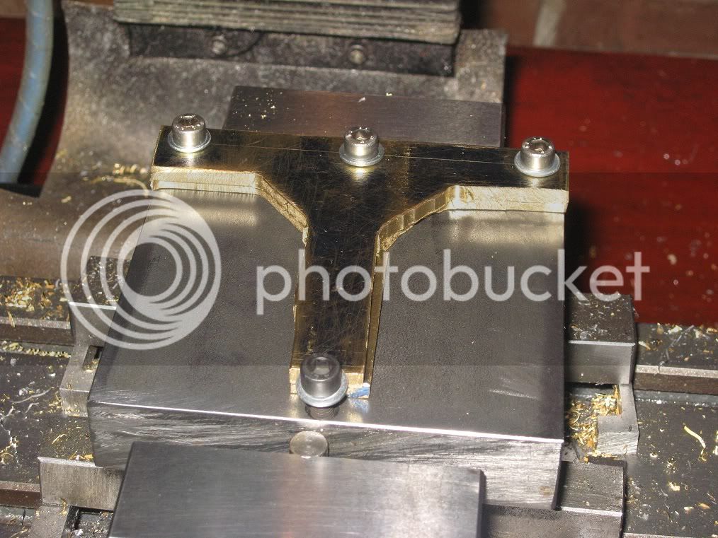
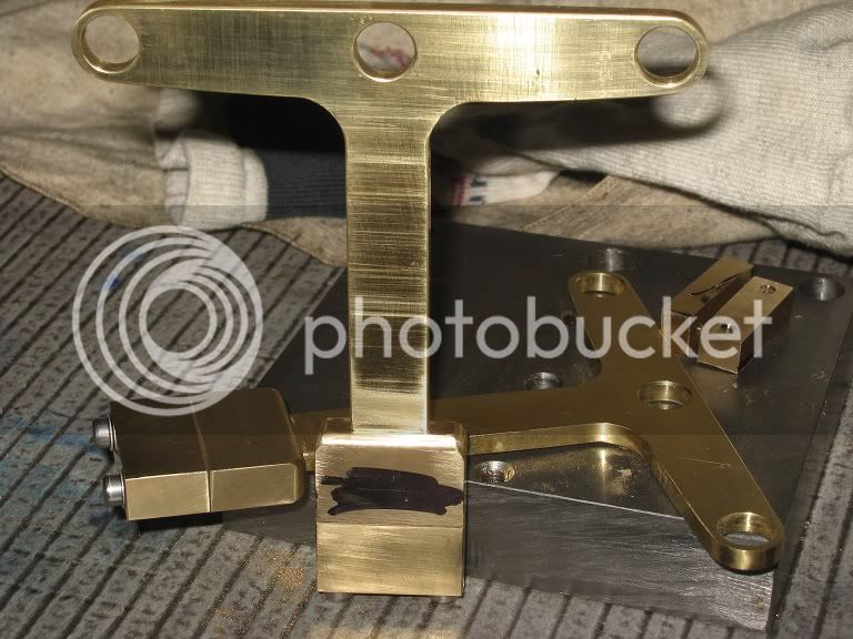
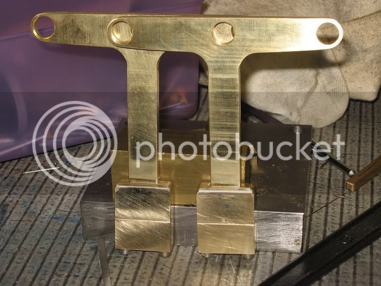
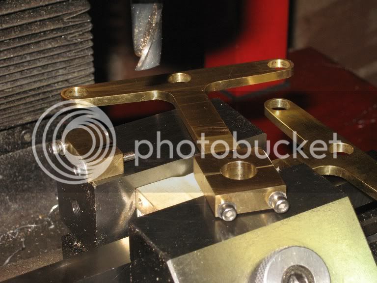
Back on the waterpipe crosshead and al. steam chests.

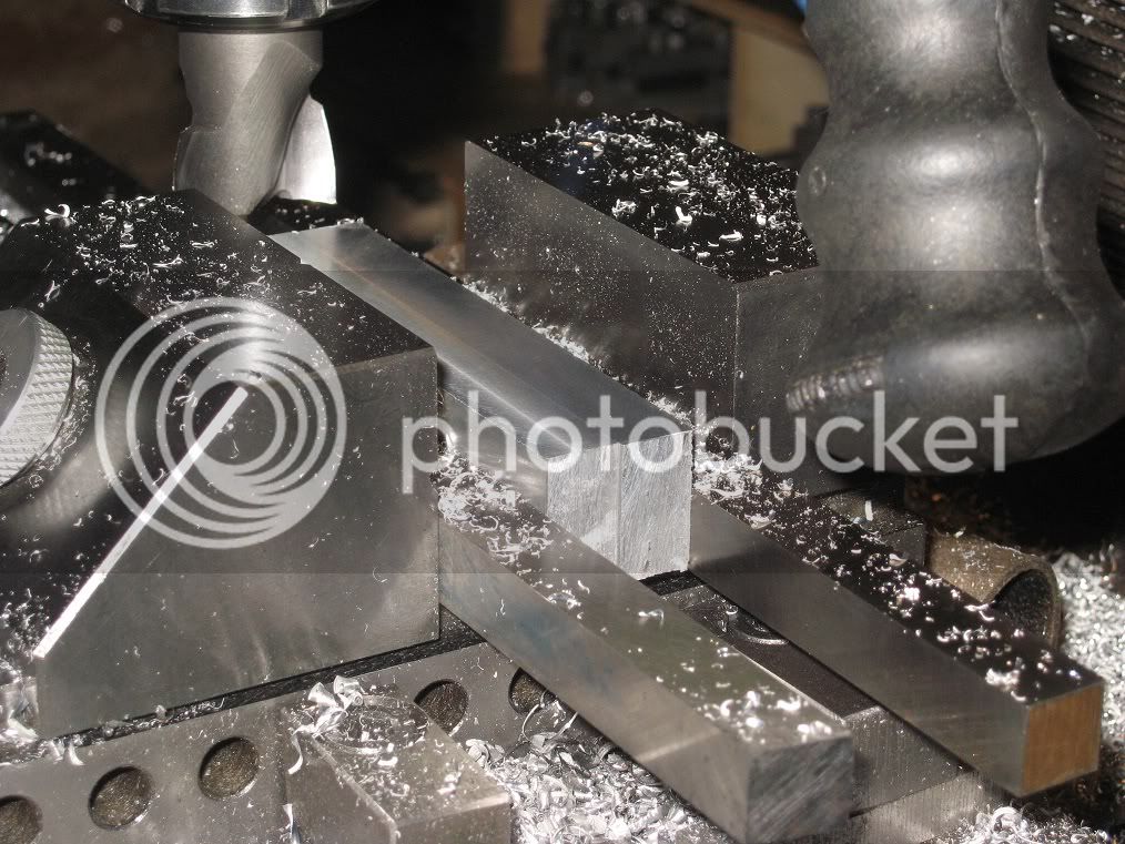
Spent too much time turning, lately: needed a little milling for a change.
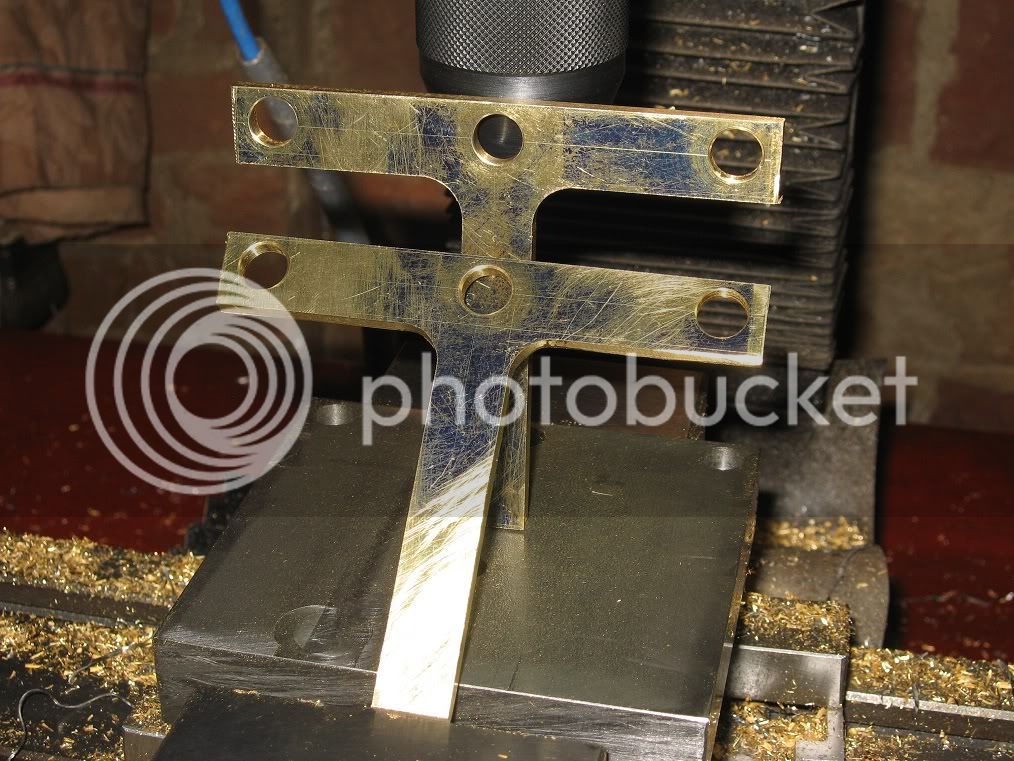
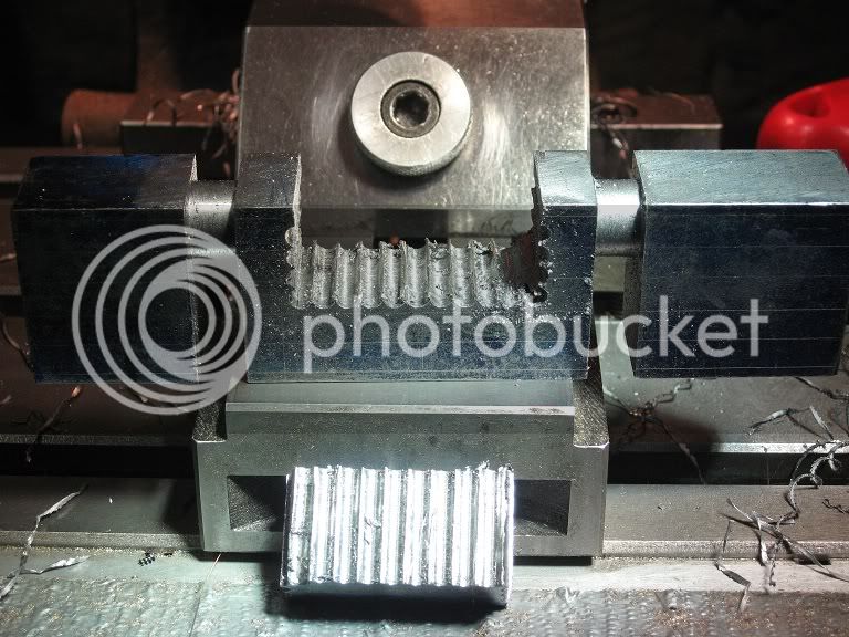
Took no pictures of the works, here’s the results, yet to be deburred.

23_IMG_0392.jpg


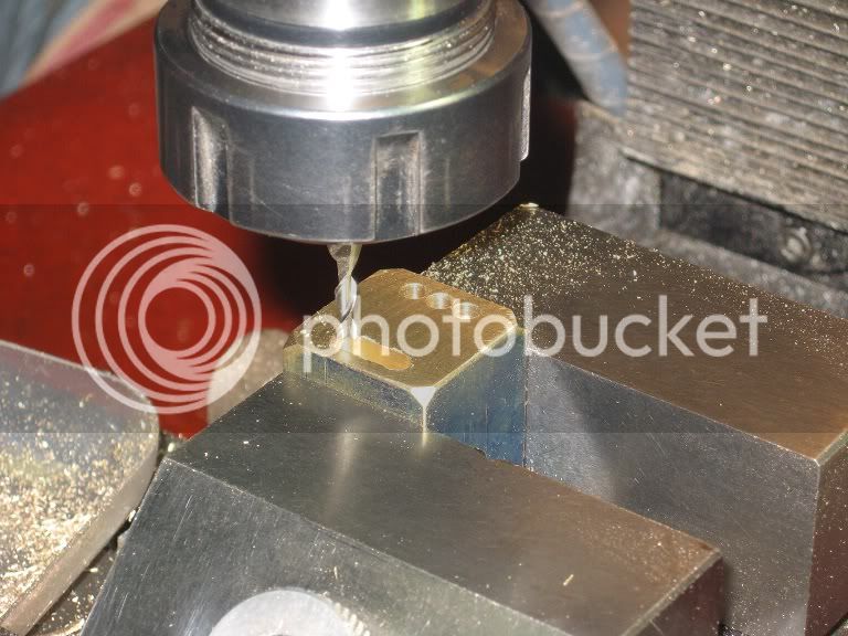
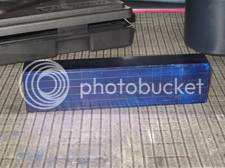
As a side note, the opening into the first steam chest came out definitely tapered. – “Strange! Sounds like a milling bit flex problem. I might have been feeding too heavily while milling”.
(...)
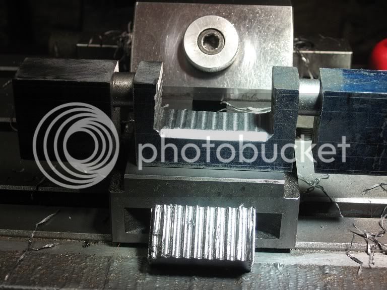
The second came out as bad as the first: “this al. is definitely a bad alloy!!”.
(...)

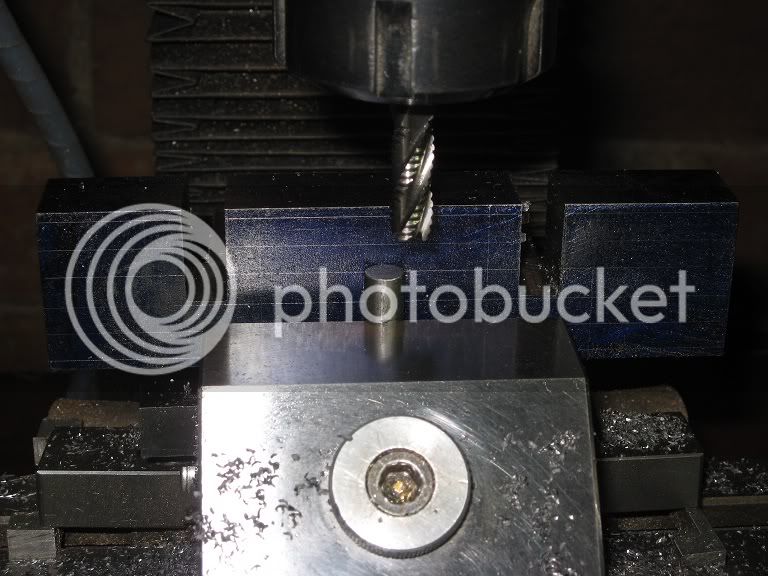
When I started milling the slot into the steel, I realized there was again more than a fair share of play into the spindle: that recent session with the large flycutter (60mm, radius) more than 1mm deep cuts...

Bet I know what You will say.

Had to spend a little time into re-setting the spindle preload.


… and back to the bronze cylinders block.

“Gotta get that done, soon or later!” (In other words, I could find no excuses to postpone this operation a little more).
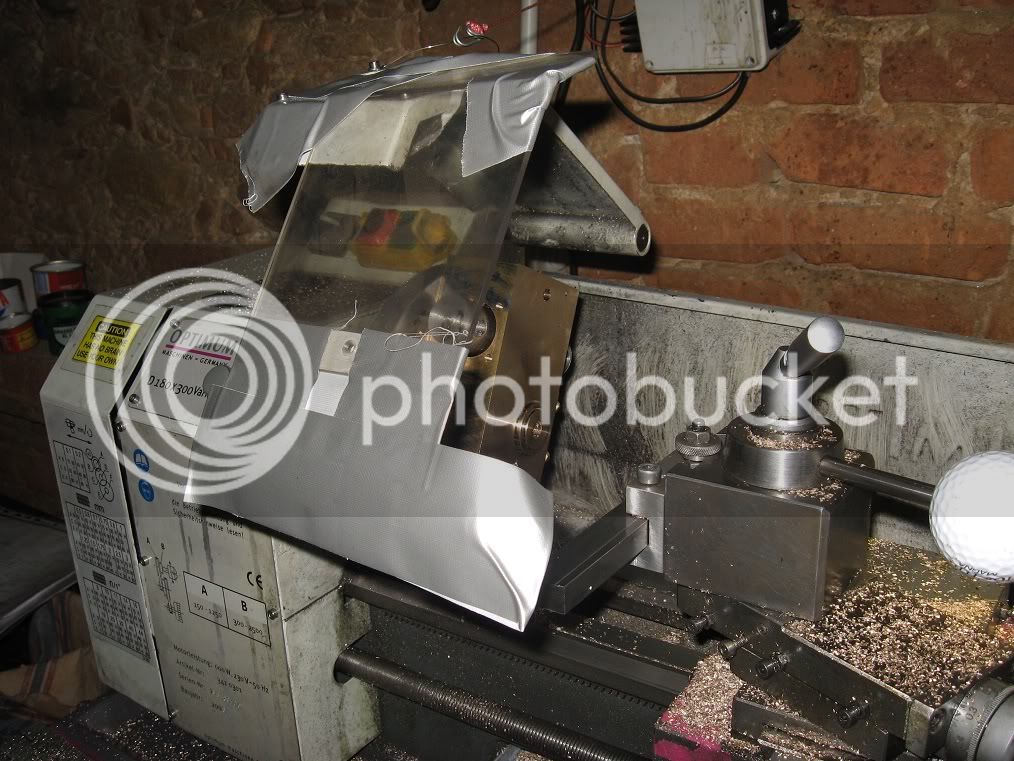
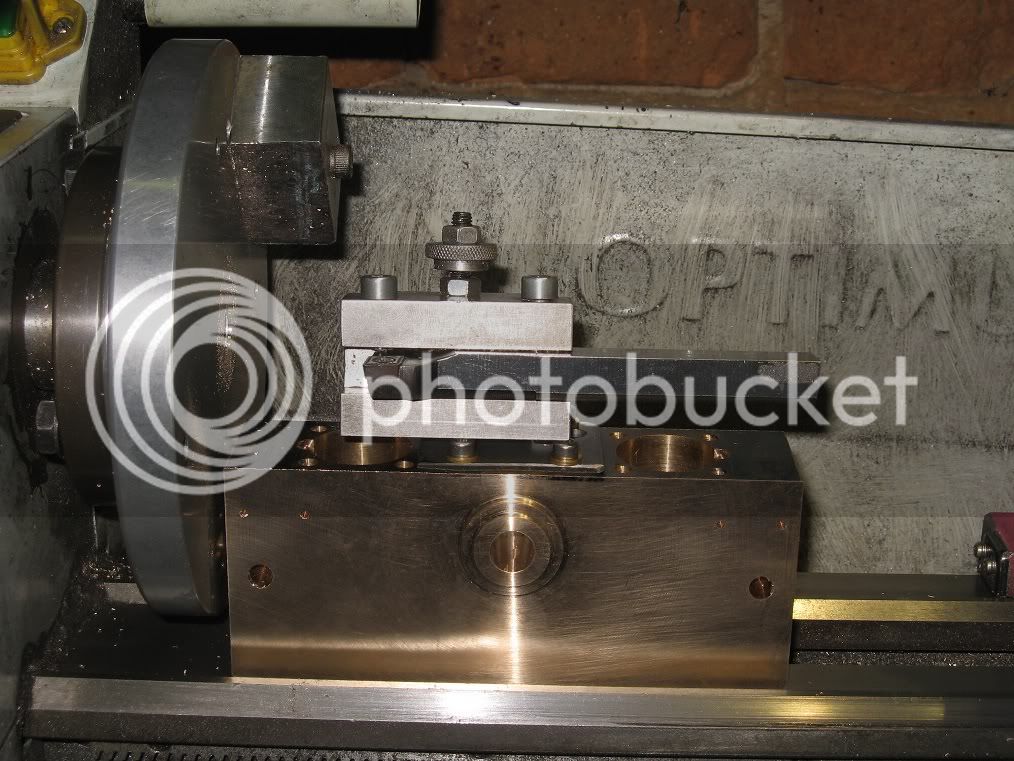
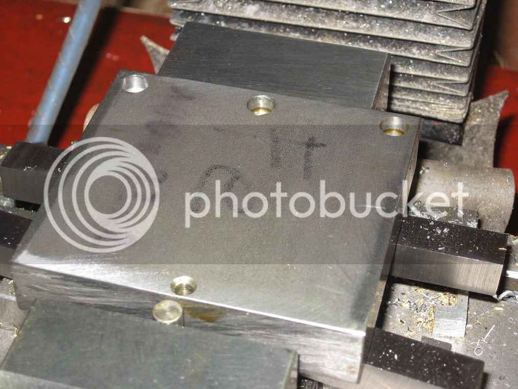
Here it is, the, still mounted on the faceplate, first side already made:


24bb_IMG_0379.jpg


It barely swung on the lathe: about 1mm of clearance between the lower corner and the V on the lathe ways.
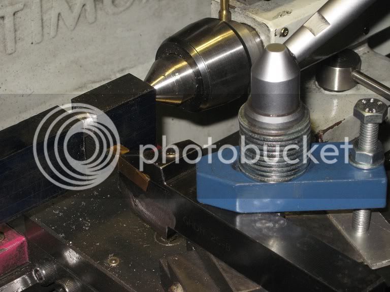
The tool is an insert holder, with a carbide insert made for cast-iron: had to mount it into the holder as back as I could to reach the external end of the workpiece.
Another option would have been a LH tool, turning the QCTP 90deg towards the operator.

Had to make a temporary chip shield extension, too.
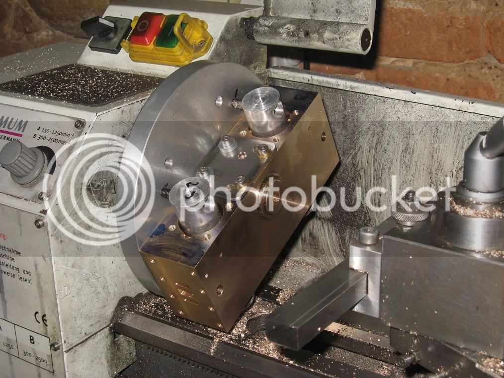
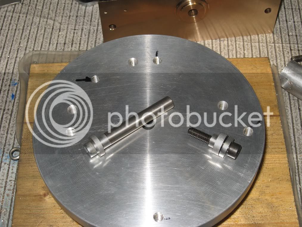
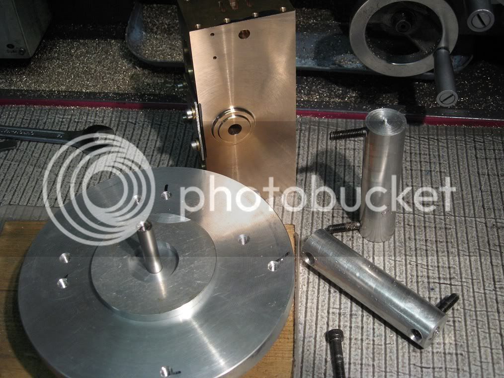
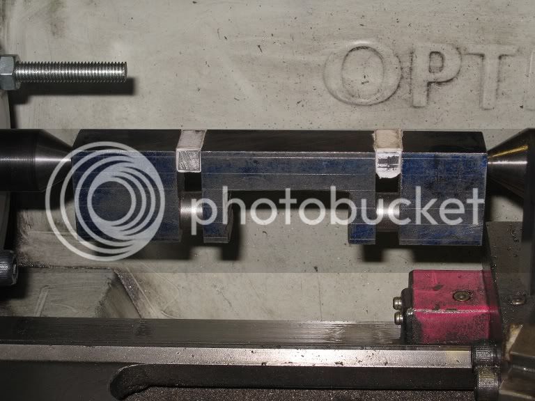
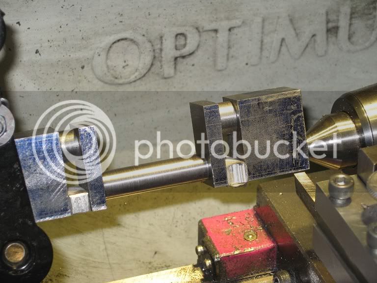
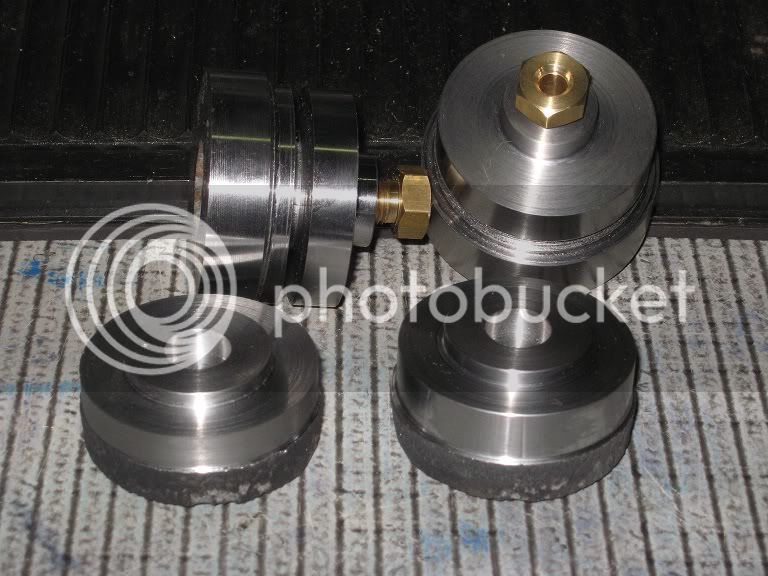
24bb_IMG_0381.jpg


Here’s how I mounted the block:

The 8mm rod fits nicely into the faceplate hole and into the (still undersized) crankshaft hole of the cylinder block: that should ensure alignment.

25_bb1_IMG_0385.jpg


The two aluminium rods will go through the cylinders bores, and the aluminium disk on the faceplate will accept the already machined bearing taper

25_bb2_IMG_0383.jpg


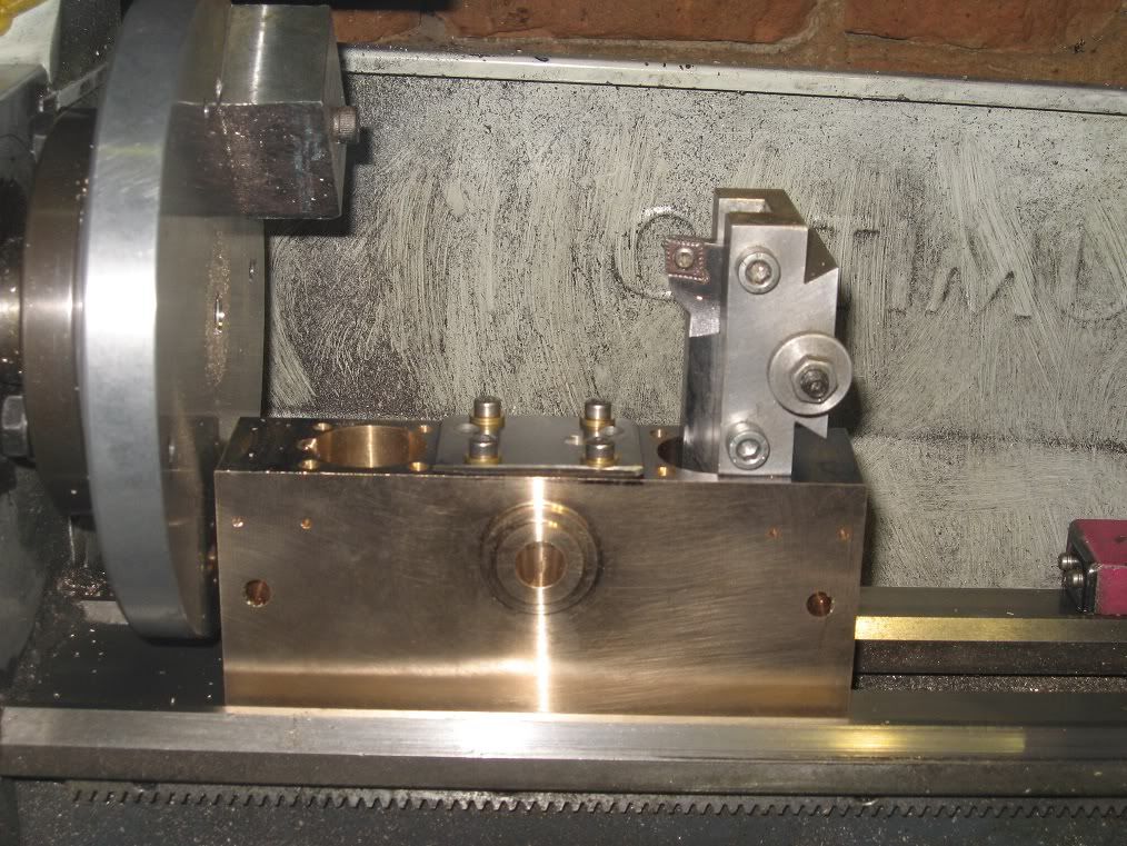
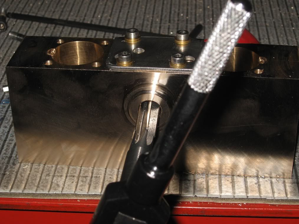
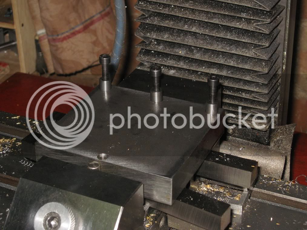
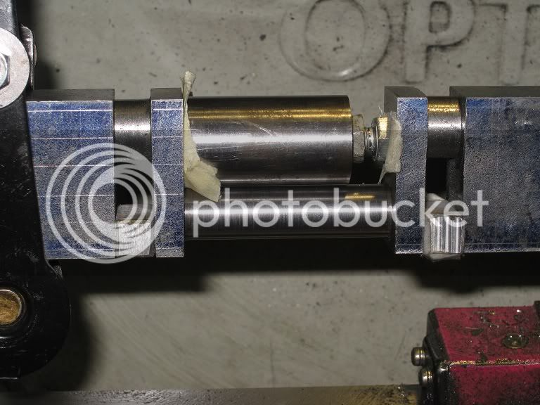
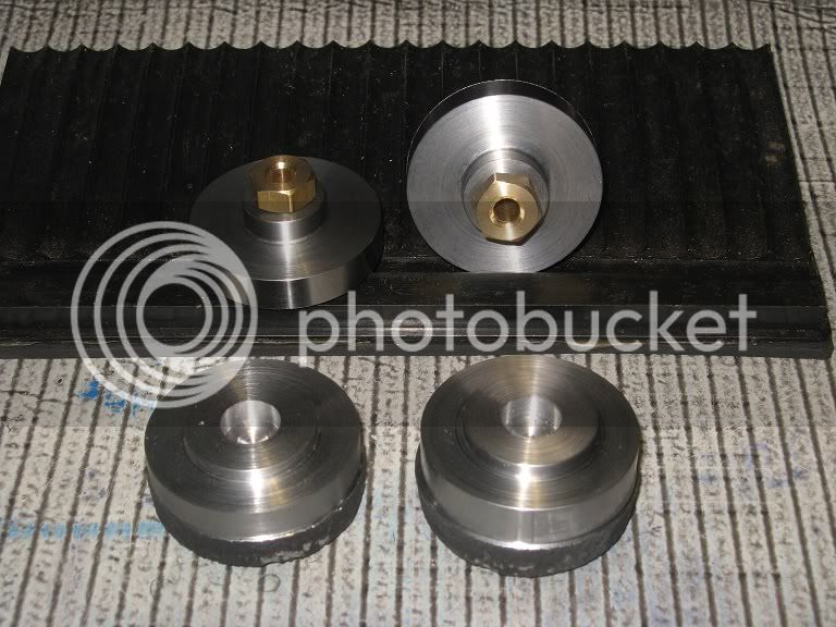
A couple of pictures of the finished block, with the crankcase bore already enlarged to 11.85mm (drilled to 10 and then bored to the final size) and the tool I had used to face it.


25_bb3_IMG_0391.jpg


25_bb4_IMG_0387.jpg


You have probably noticed there’s a counterweight, still mounted on the on the faceplate, if not its absence in the previous pictures: definitely, a must I should have added before.
I could complete the first side without it, by turning the wp. at very low speeds, but it took soooOO long…
Much more than what I spent into drilling a couple of holes, and tapping the one I had put on the faceplate.

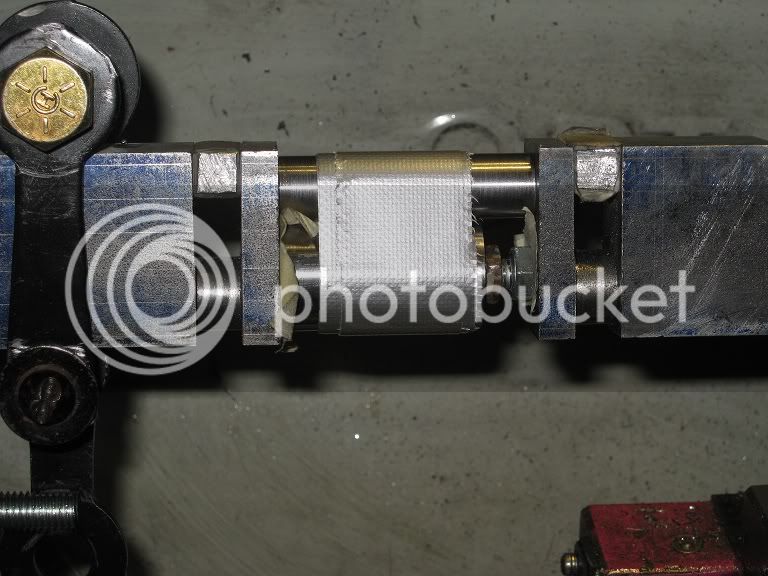
Reaming the crankshaft bore, to the (chosen) final size of 12mm.

25_bb5_IMG_0386.jpg


Marcello

 
Small progress

Had very little time left from work lately: the shop was freezing cold, and I figured that chopping woods, shoveling snow and occasionally giving heat to iced water pipes was much more fun than working at the lathe or mill. Sort of.

Anyway, I managed to make some bits and fittings:

The piston rod gland nuts, turned from the 12mm hex brass bar, tapped M10x1, now being chamfered on the outer end.

26_IMG_0394.jpg


The feet

made them in pairs from some al. offcuts.

26_IMG_0397.jpg


A nice surprise.
Got a phone call from a friend, one evening: “show Yourself at the pub, tomorrow. Got something You’ll appreciate”

26_IMG_0398.jpg


They’re all finely grained cast iron!! but for the flywheel (gear) blank which is steel. Definitely appreciated.

I was a bit worried about scale, hard spots or blows (they were risers from castings) : turning and facing four or five of them revealed no flaws.
But I don’t think the lathe will ever get clean again, however hard I will scrub it.

Used one of them to make the pistons (though the use of CI pistons into bronze/aluminium cylinders makes me wonder…).


26_IMG_0404.jpg


A temporary mounting of what I’ve made so far.


26_IMG_0408.jpg


The piston rods.

After drilling some holes into the steel block to remove the bulk of metal, I milled a pocket to (my) size and then slit the ‘finished’ part.


26_IMG_0411.jpg


26_IMG_0413.jpg


As it goes, I drilled the first hole for the 6mm shaft using a 5.8mm bit: result, was a fit a bit too-tight.
When I enlarged the hole with a 5.9mm bit I got it exactly how I wanted it to be. Drilling the next three holes using the 5.9mm bit (without pre-drilling 5.8 ) it brought an almost sloppy fit.
Sure, not tight enough to hold the shaft in place. (GRRRR!!!)
A bit of light knurling on the ends of the piston rods should solve the problem, maybe some loctite, a cross pin… …all the above options.

Marcello
 
Connecting Rods

The two items were sawed and milled roughly to shape from a 4mm brass plate

27_connRod_IMG_0448.jpg


Then, I drilled and tapped M5 four carefully spaced holes on a piece of scrap (that’s iron, not even steel), three of which were subsequently counterbored 9mm dia. for a depth of 7.

27_connRod_IMG_0456.jpg


After a few minutes spent on the on the lathe, the simple fixture was ready to hold both the blanks in place.

27_connRod_IMG_0459.jpg


27_connRod_IMG_0461.jpg


Then, I chucked a 15mm end-mill and brought them near to dimensions, cutting full depth: they still need rounding the ends and tapering. That will probably be filing work, for a change.

27_connRod_IMG_0463.jpg


As for the making the bearings, which are plainly missing at the moment, I still have no clear ideas: will have a look into the metals shelf next time I will go to the shop.

Marcello
 
Connecting Rods (continued)

Here, I’m chain drilling and milling two pockets on the top of a 25mm brass square

28_connRod_IMG_0471.jpg


Next, came the splitting of the item, milling to size, polishing, and then filing the lower edges of the connecting rods.
Here they are, together with the still unused filing buttons.

28_connRod_IMG_0473.jpg


Tried to press fit the rods into the bearing area, using the bench vise, but they showed a tendency to bend: solution came through holding each of them upside down into the vise (aluminium jaws) and hammering the bearing area in place, having a piece of plywood interposed among the bearing and hammer face.

Here’s a picture of them, the bearings already split, ready to be drilled (and reamed?) for the crank.

28_connRod_IMG_0482.jpg


At this point I realized I had forgotten putting a bit of loctite into that hammer-fitted joint: I’m quite sure they would not move anyway, but decided to drive a few nails through them, just to make myself sure ...

Almost ruined the job when I broke a bit (1mm dia.) into one of the holes but with a lot of patience (and another sacrificial bit) I managed to get it done.
After driving them into the holes, I cut those (soft iron) nails a little longer then needed and punched them into the brass forming some sort of head on each side. I suppose that will do for the entire five minutes working life this engine is gonna expect.

28_connRod_IMG_0484.jpg


Crankshaft

However hard I tried to postpone this moment, time came: I definitely need one on this engine.
The blank is pure unknownium (hope that’s steel, not iron) not large enough (only 35mm) and, worse of all, already to size.

29_crankShaft_IMG_0492.jpg


Milling the webs was easy: that Dormer 8mm roughing mill cuts steel like butter.

29_crankShaft_IMG_0493.jpg


Working among the centers, for the first time on this lathe. I soon realize I have no lathe dog, nor driving plate.

29_crankShaft_IMG_0495.jpg


The driving plate came from the ER32 backplate I had made some Years ago, the dog.. ..well, I had that couple of car safety belts locks hanging around the shop for Years, hating the idea of throwing them away.
Loda springs inside the plastic cases, too.

29_crankShaft_IMG_0498.jpg


Had to content myself with turning the bearing areas, still oversize, for the day. I need to make myself a few more tools to get it done.

29_crankShaft_IMG_0500.jpg


Marcello
 
A coupla quick question about the above cranckshaft: am I more likely to see it distort while milling/sawing the main bearing area or while turning? i/e should I roughly mill the whole shape and then go to the lathe or finish the eccentric bearings and then go for the main?

I'm slowly getting into the opinion I should have machined the larger bearing first.

TIA
Marcello


Hi Marcello,

Well, if it were me.....and I hate crankshafts...for the reasons you state :big:

You started just fine, Now that the throws are done, I would perhaps clean up the cheeks a little and then glue in some steel filler blocks to support the part. The blocks need to fit well!...so spend some time fitting them. Then I would rough out the stock on the mill and finish on the lathe. A little heat from a torch will make the glue let go later and you can clean up with acetone.

I think your doing fine.....multithrow cranks are a pain in the )*@&$( !
Just my opinion, worth what you paid for it... ;D

Dave
 
steamer said:
clean up the cheeks a little and then glue in some steel filler blocks to support the part. The blocks need to fit well!...so spend some time fitting them.

There are faster(?) ways, BUT I DON'T KNOW WETHER THEY WOULD WORK OR NOT. ;D
Yet.

BTW, I plainly forgot cleaning three out of four cheecks before cutting away the main bearing area. :-[
Now I have nicely mangled surfaces everywhere I could make good use of flat ones.
Something to do with thinking about the next step while still in progress on the current one.
Oh well, I have a few good files.

Marcello

 
Crankshaft (continued)

Here’s the tool, shown into the temporary mounting I used while I’m waiting for a skilled hand to come and solder a dovetail to the shank.
It worked very well into cleaning one of the cheeks, not so into turning the throws. (The cutting edge being 8mm wide: a bit too much for my 7x10)
Some grinding work on the insert (a notch in the middle of it) should help when I will turn the main bearing, where traversing the cutter will be possible.


30_crankShaft_IMG_0506.jpg


In the meanwhile, I experimented a bit with finishing cuts, on the still oversized throw bearings: my T-blades revealed to be too thin to be used with that overhang (they flex)
but a cutter purposely ground from a 8x4mm vanadium bar brought decent results.

Now I’ve gained some confidence into machining the throws, I’m willing to see what happens to the main bearing area.
A bit of chain drilling (3.9mm bit, holes spaced 4mm).

30_crankShaft_IMG_0508.jpg


The munched area on the top left being an extra hole to let the hacksaw blade turn 90 deg. when cutting the vertical area.
A few minutes later, I realized the little hacksaw I planned using for that part has no means of setting the blade at any angle but vertical.

Had to do without the frame.


Sawn.

30_crankShaft_IMG_0514.jpg


And a bit of filing, just for the fun of doing that.


30_crankShaft_IMG_0517.jpg


Marcello
 
Crankshaft (continued 2)


With the throws bearings still oversize, I decided to finish the main bearing area.
First of all, I cleaned the cheeks to ‘finish’ and then searched the scraps box for a couple of items to be used as temporary fillers for the gaps.

Two short portions of aluminium square wrapped into a strip of writing paper till they got a push-fit (finger force only) among the cheeks may solve the problem.

31_crankShaft_IMG_0518.jpg


Then it will only a matter of bumping the workpiece against the cutting tool for a long while. That cutter id definitely too wide for the job on my little lathe:
ended with cutting a thin groove with a parting tool on the HS. side, subsequently enlarging it using only half of the big cutter.
As You can see, the finish is ugly, and I’m slowly tapering the bearing. But the job is getting done in seconds.

31_crankShaft_IMG_0521.jpg


Later, I cut a second grove almost to depth close to the TS. cheek and traversed the tool back and forth till it was almost to size,
switched the cutter to whatever material that bar is made of and finished the part to a close fitting with the bearing.

31_crankShaft_IMG_0523.jpg


Had I been a little more confident into my skills of bringing it to the correct size, I’d have left this “finishing” where it should be: the last operation.

Back to the throws, I filled the gap into the main bearing area with rod and screw, interposing a couple of strips of paper not to marr the surfaces.

31_crankShaft_IMG_0526.jpg


Got curious about the eventual distortion into the workpiece after a good locking the screw: a few tenths of millimeter. Bet it would be too much.
Filed a nut, turned the screw VERY LIGHTLY ad prevented unwanted motions by locking it in place through the nut.
In a few tries, I got a distortion of about 2 hundreds (of mm). I can live with that, but would not trust spinning the object without having taken some safety measure.

31_crankShaft_IMG_0528.jpg


I realized I could make use of some gauge when bringing the throws to size. What about the connecting rods themselves?

One of them is shown into the vice, wrapped into paper so I can slid and screw the foot in place after finding the edge and centering the cutter among the vice jaws.
Drilled a pilot hole and enlarged it using a plunge mill to whatever size it came.
It came out a bit less than the 12.065mm reamer I had, so that will be the throws size.

31_crankShaft_IMG_0530.jpg


Here’s the thing, I will break the sharp edges through filing.

31_crankShaft_IMG_0534.jpg


More Heads

Some more shop time to spend, with no intention of working to close tolerances: just interested into filling a basket with coiled swarfs.
Two head broke while tapping them, two are still missing…
The steel blanks I used had a thick crust, which had to be removed before they’d give a decent finish: as it goes, I got six of them undersize, while making the four shown below.

Left the hacksawing for another day, took the picture, cleaned the hands..

32_heads_IMG_0535.jpg


..and changed my mind.

32_heads_IMG_0538.jpg


Marcello

 
I just virtually finished building my engine and thought I would share hope you all like it. :)
Get it virtually.... :D
PS. Keep up the good work Marcello.


01.jpg


02.jpg
 
Darren,

nice work on that model: now, get to the machines and show us the real thing. ;D ;D
Marcello

--
PS.
Does it 'move', if run into whathever program You used to make it?
 
Thanks Marcello. Yes it does run in Inventor 2012 Pro, but I don't know how to record it sorry :(
 
If You ever get around recording a movie, please, do not forget posting a link: I have ideas it would be nice watching at it.

Marcello


Latest posts

Back
Top