Bernay build - MZT

Home Model Engine Machinist Forum

Help Support Home Model Engine Machinist Forum:

This site may earn a commission from merchant affiliate links, including eBay, Amazon, and others.

Connecting Rods Bushings

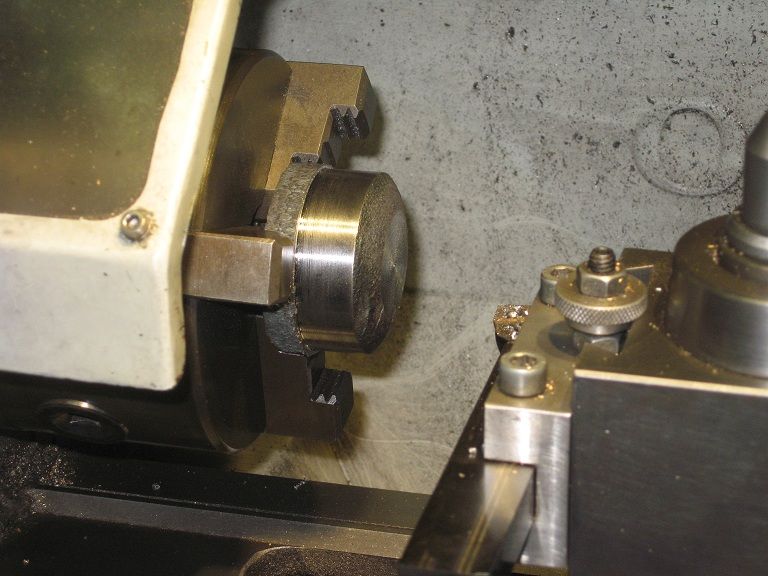
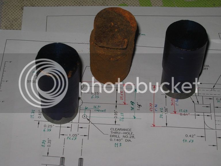
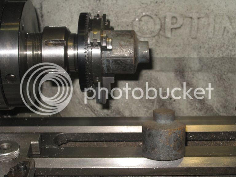
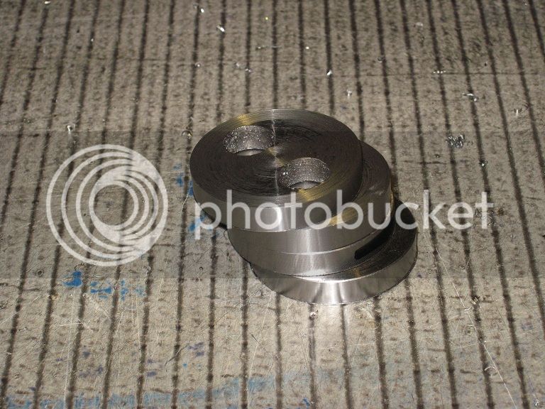
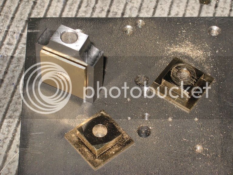
Had a small chunk of bronze rod with dozens of blow holes in it: the right material to make short bushings (providing You’re positive into discarding two third of the semi-finished parts)

33_connRod_IMG_0553.jpg


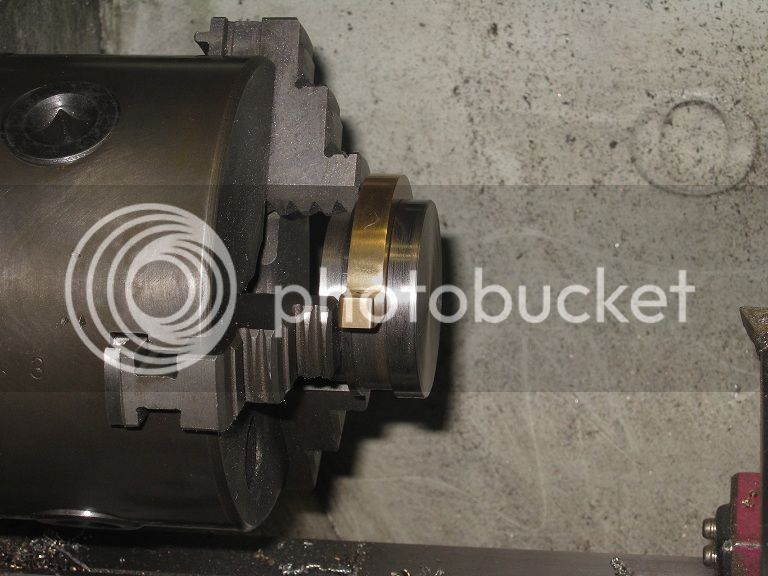
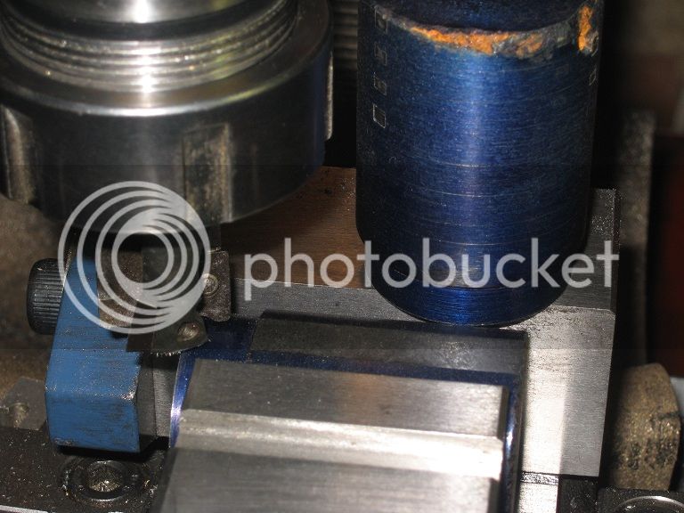
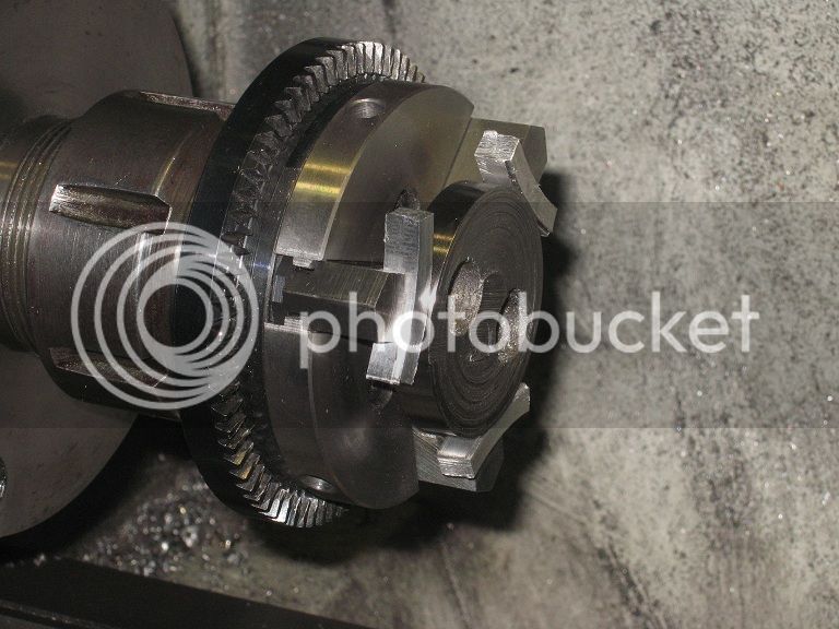
One of the bushings had a too light interference with the hole in the rod: at some point during the reaming it started turning.
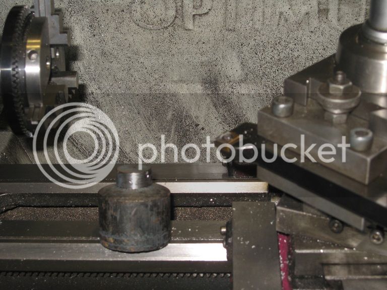
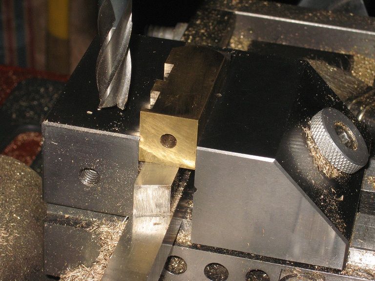
When the long line of self expressed comments finally ended, I went for a gentle squeezing of the part into the bench vise:
the deformation I got (on second try) was enough to set it firmly. And that should do.

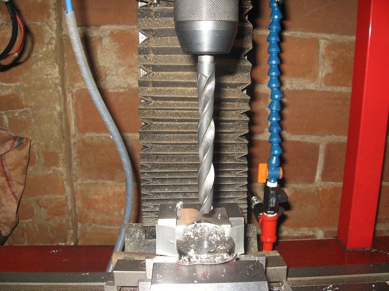
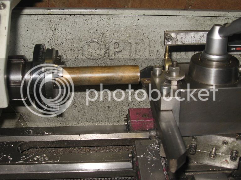
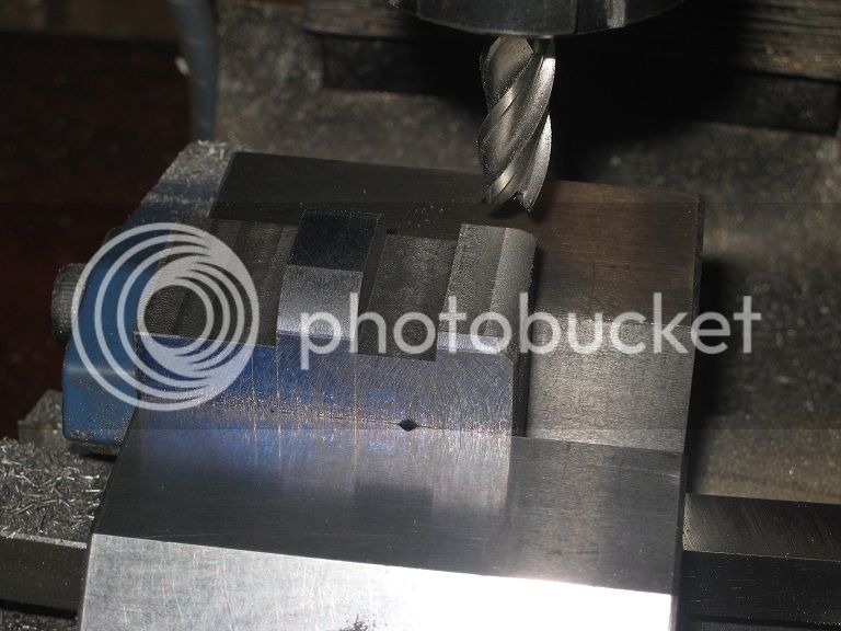
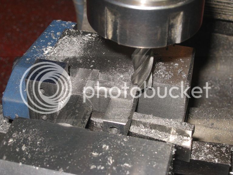
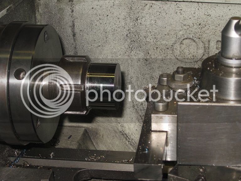
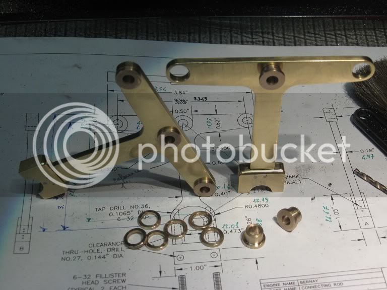
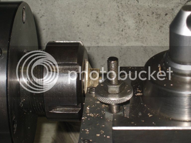
Then, the sixth of the bushing rings cracked partially while being driven in place: it took quite a while of fiddling with needle files and
sand paper to realize I had that already turned and bored to size rod still set in the lathe chuck, even the hacksaw blade parting tool still
in the post. One minute? Probably less.
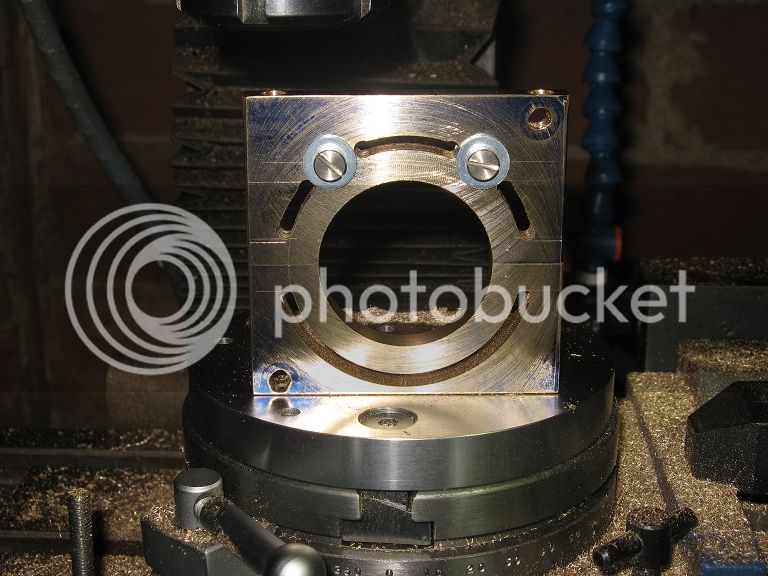
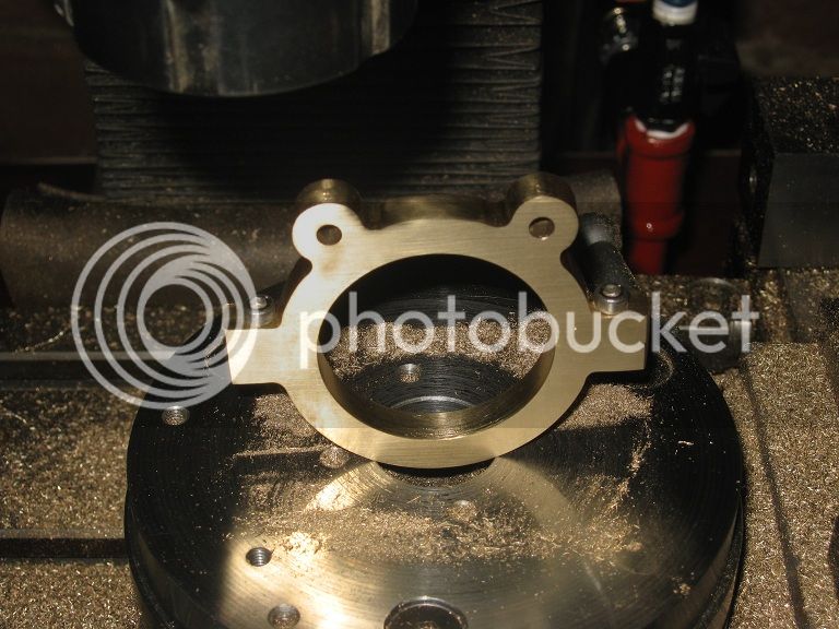
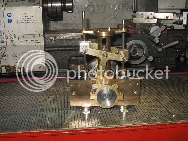
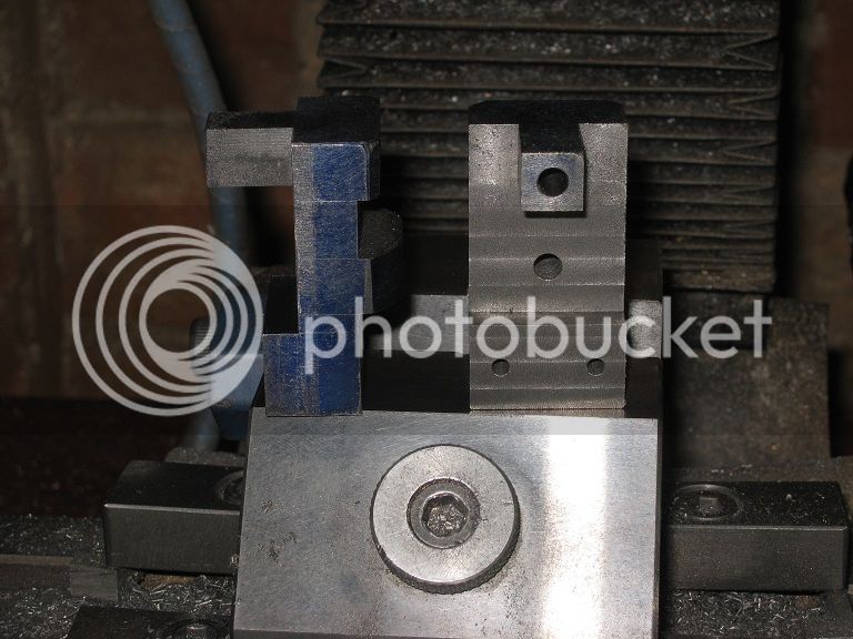
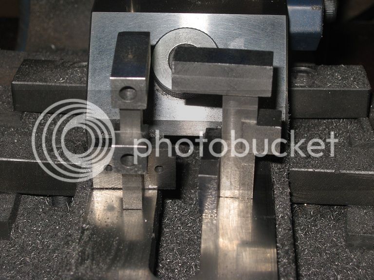
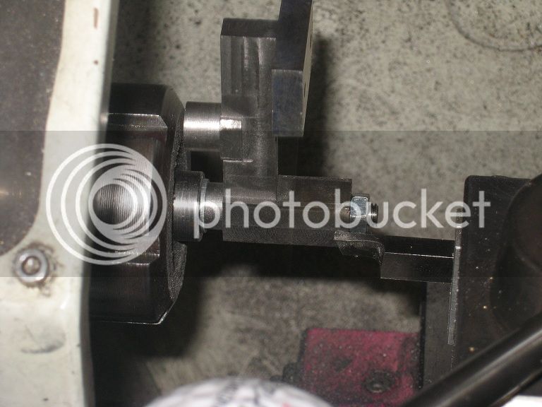
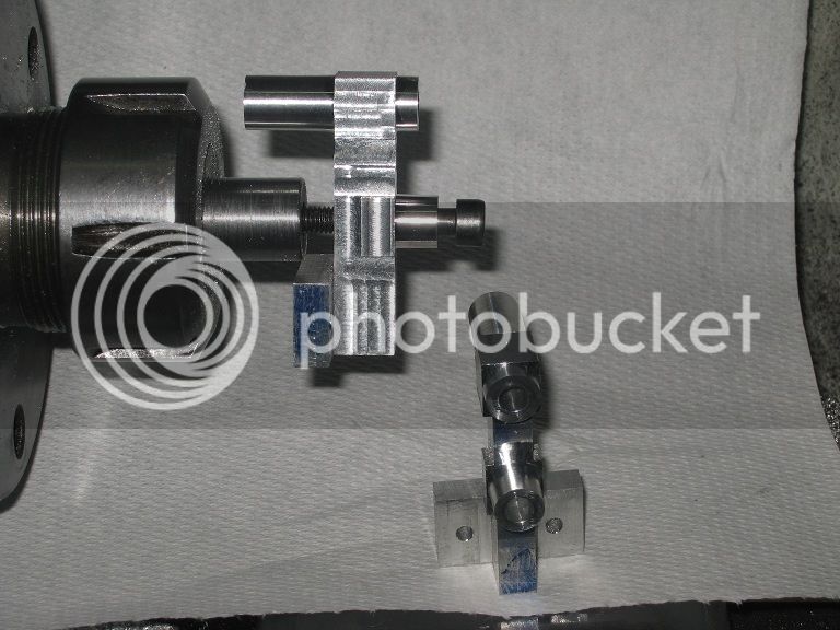
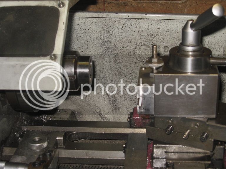
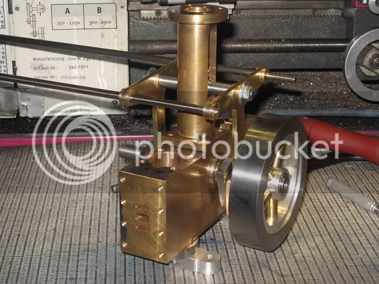


First assembly

Now that thing starts looking like an engine!
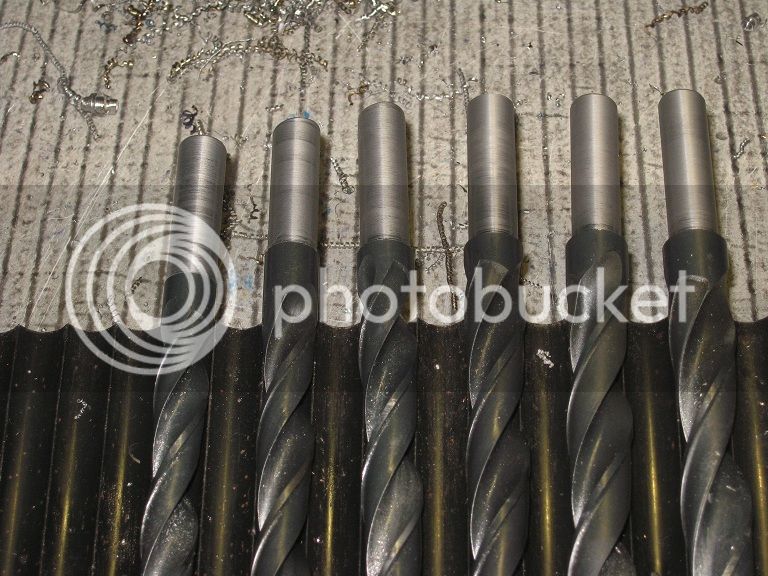
The two (long, You see) 6mm printer shafts were rather stiff into their bushings: after a while, I removed them one at a time and
hand reamed the bushings in line. Another bit of oil ..hey! It turns smoothly!

34_1stAssemby_IMG_0558.jpg


Having (in hindsight, regretfully) spent most of the remaining shop time (and there was still plenty) playing with the moving parts,
I found no points into wasting my dinner time into the same activity…


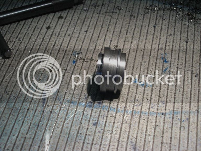
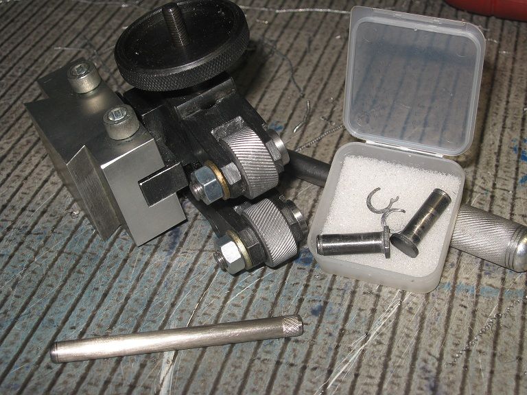
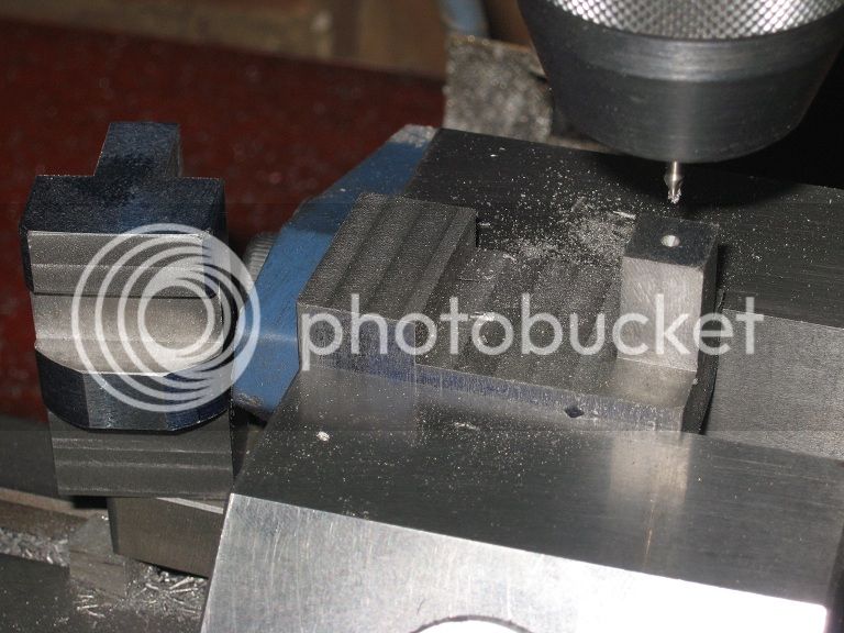
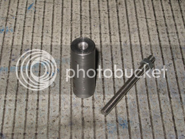
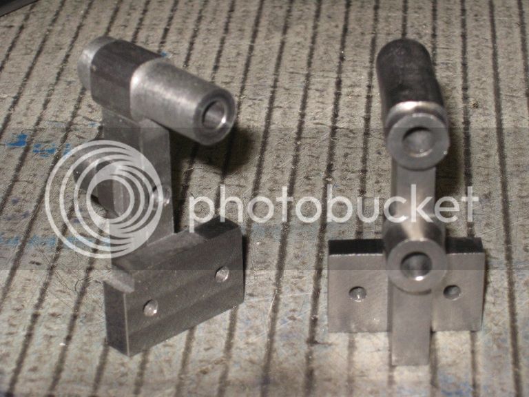
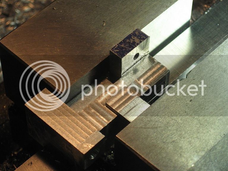
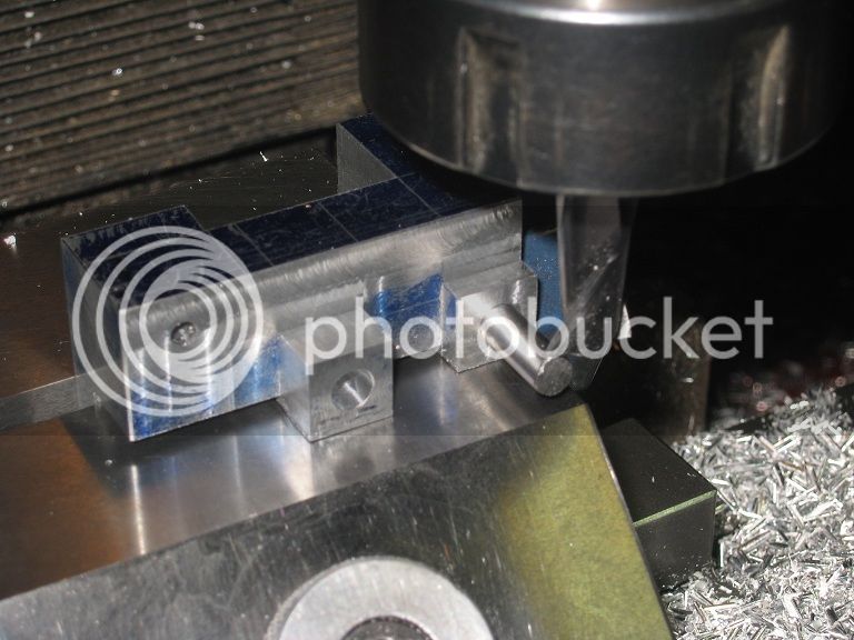
Connecting Rod Shafts (..of course)


They were supposed to be made into two pieces only (to say nothing about the diameter reduction from ½” to 10mm) but I had
a 6mm threaded bar just a little bit too long to fit into the so labeled box. Now, I can close the lid.


35_ConnRodShafts_IMG_0560.jpg


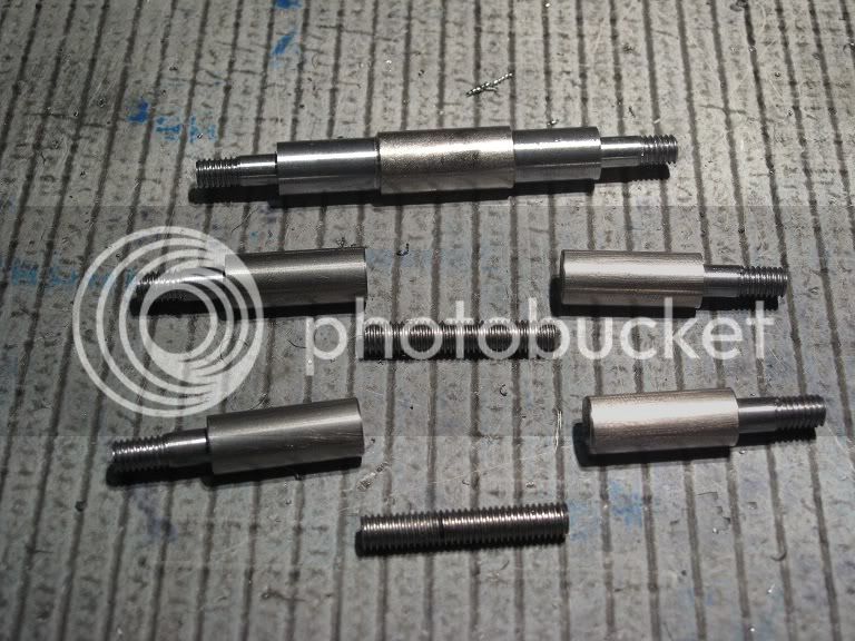
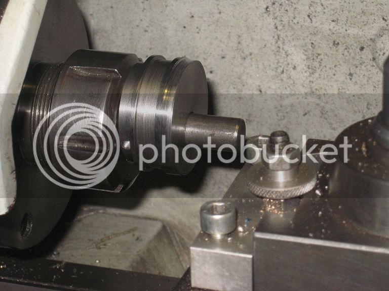
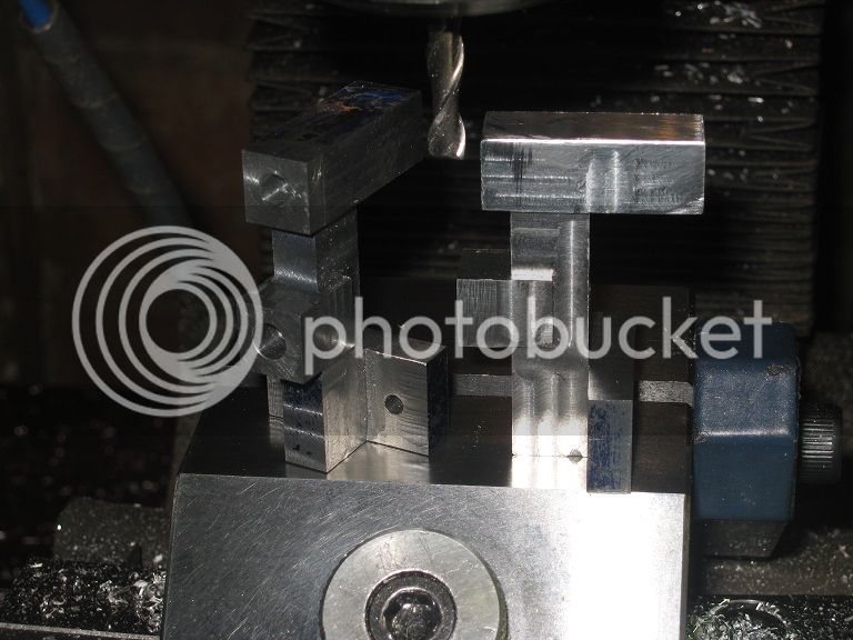
I left them slightly over length, just in case I got a bit creative with the dimensions of the parts they will be fitting to.
As for the missing runout groove clearly not visible on those threads, I decided to postpone that work till I will grind a thin round
nosed grooving tool purposely made for the job, the parting tool being too wide and the hacksaw blade too thin.

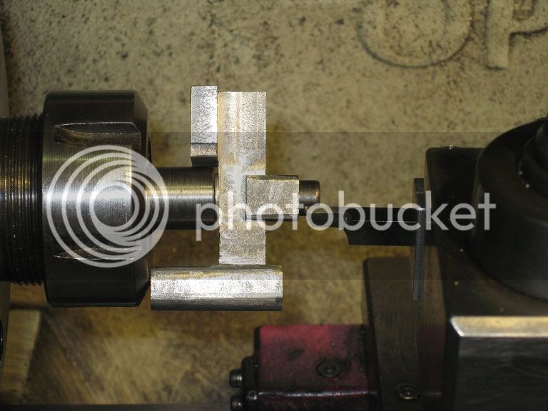
As it usually happens on the (frequent) occasions I wander from the drawings, the single-piece “crosshead pin and bolt” cannot
be set in place unless BOTH the connecting rods were disconnected from the crankshaft.
Not sure it can be seen as an improvement.

Marcello
 
Eccentric Strap


Had no brass plate thick enough to make it, no better option than hacksawing a portion of a brass block.
Here it is, the first cut already made, scribed and ready for the second half.

36_EccStrap_IMG_0580.jpg


Before cutting it, a second check on the metal shelf revealed a brass remnant large enough to make the lower part of the strap. Its thicker than needed, but not much.

Here’s the two of them, already milled on all faces and drilled for the joining screws.

36_EccStrap_IMG_0586.jpg


The two parts fitted together and roughly scribed: I will probably use the DRO and ROT-table, but a visual check of what I will be doing...

36_EccStrap_IMG_0588.jpg


Had I checked twice the drawings before drilling the screw holes, I might have put the clearance holes on the correct part.
Now, I will have to insert the mounting screws from the top, or drill again and make use of bigger screws.

Will face that the day it will come.
For today, I’ve really no interest into working with the rot-table, will use the remaining shop time to make some more small items.


Piston Rod Inserts

Material is 20mm brass square: I set it vertical in the vice, faced the top and drilled a 5.9mm hole through the center.

Next, I set it on a couple of stacked cheap man parallels and hogged a 12mm wide full depth (minus ‘safety’ allowance) slot on the four sides,
taking care to have the workpiece re-aligned with the vise jaw side anytime I turned it 90deg.

37_PRI_IMG_0590.jpg


The four pieces were then hacksawed and filed to a ‘nice fit’ into the matching area of the piston rods.


Machining the outer surfaces was no problem: I just fit them into the vice and face milled away all the unwanted material, maybe a little more, maybe a little less.
All I wanted was having the four of them as identical as I could.

Holding them inserts by the larger square to machine the roughly hacksawed inner surface is a bit different: aint sure the vice would hold the wp. on that thin surface.
I could figure a few safe ways to do that, but had to sit for a while in that (comfortable, really) armchair with a cup of tea to think for the best one.


It took a while…


When I was awake again, I decided a mandrel in the lathe would do.

Made use of the already present hole in the items and screwed them to the mandrel, by interposing a paper washer not to marr the external surface should they slip.
Then used a parting tool to remove the metal till it reached the screw head, and made the four of them in a row.

37_PRI_IMG_0591.jpg


The little area that was under the screw head was then filed away.

37_PRI_IMG_0594.jpg


Connecting Rod Shafts and Piston Rods


Took no pictures at all, sorry.

Now I had the inserts finally brought to size and polished, I could take a few measures and bring the connecting rod shafts I had left a bit too long to the correct length.
As simple as chucking them in the lathe and facing .55mm from each of them.

Then, I mounted the engine, measured more than carefully, and cut the piston part of the piston rods to a fitting length.
It came 5.5mm shorter than the 3”.01 + ((0.90 - 0.504) / 2) shown on the drawings, but the piston travels the same amount of cylinder on both strokes* and that should be ok.
Won’t know for sure for another while.

Another dismounting and remounting (how many more???) of the whole engine to fit the heads gave the pleasant result of having the parts positively checked for smooth moving.


Marcello

---

*) On drawing B1-D, I could not find a way to calculate the distance from the top centre hole to the bearing centre.
Bet I made some error when I took it from the graphics scale.


38_B1D.jpg


Cannot say about the 3".25, I don't think I have the sheet of cheese paper I used to write it down, still.
Can still measure the distance between the centers, tho. But not at the moment.
Thank You for showing me how: NOW, it is obvious.

Marcello

 
That measurement is close, but the rod slopes down across the top, it is not flat.

The correct distance is 3.21".


That is some beautiful work you are doing Marcello!

I enjoy seeing your nice set-ups.
 
UNIcastings said:
That measurement is close, but the rod slopes down across the top, it is not flat.

The correct distance is 3.21".

Oh well, I had written the measure taken on the scale on the drawing itself: 3" 7/32. Same value on the part itself: close enough, for my standards.
Not that I mind much about those missing 5.5mm (as long as the engine will run): as usual with my engines, from some point on the build has to switch towards the 'made to fit', taking the figures printed on the paper as general ideas about the parts dimensions. THAT'S DUE TO THE ROUNDINGS TO THE CLOSEST METRIC HUNDRETH WHILE CONVERTING FROM IMPERIAL MEASUREMENTS (and I dare You to believe into that. ;D ;D ;D).
Please, do not ask why I'm rarely working on metric plans.

On that same drawing, the left and right bearing are quoted at two different values: 3.5" and 3.345": I chose the second, being the same value as the distance among the cylinder axes.

Marcello


Hi UNI.
Just wondering how you actually came up with the amount of slope for the top if that is the case ?
Also if it was to the top it would be to the top of what appears to be a web and that web should be shown on the side views.
If you look all 3 top bosses are in line and the measurement is to the top of the bosses.
Just MTCW. :)

Bernay-Rod-Dimension-01.jpg
 
The drawings were developed by disassembling and measuring the engine shown below, built in 2004 by Bob Jorgensen.

How he came up with the slight angle on the top of the rod, I don't know, but he tended to give a slight curve to things to eliminate the 'flat' look.

You are correct, the web should be shown in the side views, but was overlooked.
It was rather a pain to measure and draw this engine, but I knew people would have fun with this information.

The method was to measure each part exactly, and then the intent was to round of as many numbers as possible/practical. Looks like I forgot to take out one of the initial measurements on the rod when I rounded.

Jesse Livingston modeled a similar engine in Live Steam Magazine in 2006, but it was a smaller version of Bob's engine, and Jesse left out many of the finer details of Bob's engine, so I wanted an accurate set of drawings to be out there.

Took quite a while to develop the drawings, but well worth the effort in my opinion.

rCIMG_0576.jpg
 
Back to the Eccentric Strap …

My previous scribing was no good: rather wipe off and start over.

39_IMG_0608.jpg


Now I have a visual check I can feel comfortable with, time to align the RT

39_IMG_0612.jpg


Setup the WP spaced from the holding plate by 4 washers not to ruin it and milled away all the unwanted material plus the uncareful machinist’s share.

39_IMG_0614.jpg


39_IMG_0616.jpg


4 cheap, ready made, commercial filing buttons

39_IMG_0617.jpg


And a lot of polishing.

39_IMG_0620.jpg


..then the Eccentric

Decided to turn the bearing area first, then offset the bore.
Here it is, being hugged off in the 3jaws, then grooved

39_IMG_0622.jpg


..a bit too deep.

39_IMG_0623.jpg


Another foundry scrap came out to a better fitting

39_IMG_0625.jpg


Took a break from the eccentric: now, the 10.5 to 13mm step .5 drill bits will fit 10mm keyless chucks I have on both the mil and lathe TS!

39_IMG_0626.jpg


Here’s the eccentric in the mill: centered under the spindle then offset 4.76mm. Centre drilled and drilled in a few steps to 11.5mm. Next, it’s been reamed to 12.

39_IMG_0631.jpg


Back on the lathe, held on the mandrel by the two grub screws, to complete the machining.

39_IMG_0634.jpg


Finishing the Piston Rods …

Them clips on the knurl wheels arbors had ever been a pain to remove, to say nothing about finding them again among the swarfs on the shop floor.
Here’s the result of 10’ work on a 11.5mm rod and two nuts.

39_IMG_0640.jpg


Switched the wheels to a medium coarse couple, and ruined the end of one of the top rods enough for press fitting purposes into a hole a bit too large.


..and the Top Support Bracket
where the bushing were still missing. Material is 21mm bronze, held in a collet mounted chuck to be faced and reduced to 20mm for a length of about 200.
Then, I reversed the WP holding it into a 20mm collet, and machined the two bushes to be press fitted into the top bracket.

39_IMG_0642.jpg


Some more parts going to place. A bit stiff at the start.

39_IMG_0646.jpg


Dremel polishing compound mixed with oil made wonders, after a while.


Marcello
 

Rocker arms support brackets

One of the blanks as it came from the scraps bin, and two already skinned and scribed.

40_IMG_0647.jpg


Parted to lenght

40_IMG_0651.jpg


Replacement heads

I had left them uncompleted ages ago, I took the occasion of having the lathe in a mess of cast iron powder to bring them too to finish.
Here, I’ve centered the jig and I’m drilling the bolt holes at coordinates.

40_IMG_0654.jpg


The jig. With a total of ten heads, having made it paid well.

40_IMG_0656.jpg


40_IMG_0658.jpg


Rocker arms support brackets

Back to the C.I. risers, some facing to bring them to the required sizes. The blue clamp on the side of the vice will be used later as a wp. stop,
so I won’t have to find the edges more than once for all the faces.

40_IMG_0659.jpg


Carving the shape with a 10mm four fluted mill, depth of cut being 1 / 1.5mm

40_IMG_0662.jpg


Centre drilling, drilling and reaming the required holes.

40_IMG_0664.jpg


40_IMG_0665.jpg


Working on the sides, now with a 6mm end mill. The wp. is laying on parallels (HSS blanks) and held into the vice jaws through
a short portion of steel rod. Not much of contact surfaces, but it did not move. I carefully avoided climb milling.

40_IMG_0668.jpg


Here they are, all but finished. A lot of rounding, filing and polishing is still in order.
Gotta think something about the missing portion on one of the flanges, too: it came there on the last op.
“too simple to be worth bluing and scribing” – Then, I turned the wrong wheel to the expected reading on the display.

40_IMG_0669.jpg


Marcello
 
Hi Marcello,

I have watched this from the beginning and must say it's been a very good write up and build.
I am looking forward to seeing it run!

On a side note:

Pat, your dad was a very clever chap.

Kind regards to both,

Ron.
 
Ron-

Marcello is doing a great job.
It is fun to watch his many methods and materials.
He is very creative.

As far as Bob J, it wasn't until I was able to disassemble some of his engines that I came to realize all the finer detail that he put into his work. He maintained the same level of quality inside the engine as outside.
Bob had an artistic flair, and was a very good machinist on top of that, so not only do his engines run well, they have a nice "look" to them, with just enough small subtle details to give them a finished look.
Definitely not museum pieces, but a good example of how you can quickly build some pretty nice scratch-built engines.

Pat J

 
Ron, Pat

Your words are much appreciated!
It will run someday, at the cost of being filmed while it is driving an electric drill. ;D ;D ;D

Still, sooo many parts to be made.
But aint no haste so far: I'm really enjoying the travel.

Marcello


Rocker arms support brackets(continued)

Made this simple jig with the intentions of using it to bring the brackets to a higher finish.

41_IMG_0674.jpg


Then, I changed my mind (that’s a habit!) and decided to go for a bit of hand work with files and sandpaper,
maybe a coupla small grinding wheels on a Dremel..

Managed to STOP that right before the poor thing got mangled beyond recovery: the picture below shows it being set up on the lathe.

The second picture was taken while the lathe was spinning the second bracket, the chuck side already finished.

The pictures do not show the carriage stop I set on the lathe bed to prevent cutting too deep.
The small parting tool I used is ¼” square with a huge overhang: took that into due account and never fed the cross slide more than .25mm.


41_IMG_0676.jpg


41_IMG_0677.jpg


It worked.

41_IMG_0681.jpg


They are far better than what can be seen in this picture (others I’ve taken are worse, btw),
especially the one on the right which I’ve polished using a wire wheel on the Dremel till I got it shiny.
I’m definitely satisfied with the job I’ve done.

Next two will be made differently.

Marcello


excellent build! excellent thread! 8)

it's threads like this one that makes me give my self a ruddy good kick up the bum........ to get on with building stuff.


thx :)
 
Two more rocker arms support brackets

Here’s the starting piece: being already to the same length as the sum of the brackets heights, I’ve gotta pay special attention into avoiding wandering cuts.

42_IMG_0685.jpg


Managed to do a decent job with that hacksaw.

42_IMG_0687.jpg


Flycutting the rough cuts, and squaring the faces. Love that finish!

42_IMG_0688.jpg


Scribed

42_IMG_0693.jpg


Drilled. I’m now milling all what I can using a 10mm 2fluted mill.
Just hogging most of the unwanted metal, will have to finish the work later with a smaller mill.

42_IMG_0700.jpg


Forgot about a couple of holes (per bracket). Not a precision work, here: I could use an old drill chuck in held into a collet to speed-up the tool changes.

42_IMG_0702.jpg


Into the vice, to mill the brackets sides. Had to use a piece of al. square between the workpiece and the fixed jaw, to put holding pressure on a convenient point.

42_IMG_0704.jpg


The opposite face of each bracket was milled holding them into the vice through the flange only: was a little concerned about deflections
and eventual breakages, so I clamped the top area to the big blue mill clamp I’m using as vice stop. It worked.

42_IMG_0707.jpg


Here they are: ugly as the picture can improve improve their look. I’ve never found a way to get a decent finish when milling aluminium, except flycutting.

42_IMG_0708.jpg


Jig turned on the lathe. Too early: now, I’ve gotta put many more attentions into polishing them flat areas.

42_IMG_0734.jpg


Constructed crankshaft

Being lazy, looking for troubles. (Will get them).
Didn’t want to waste time switching the lathe from collets to 3jaws to machine a short portion of the two blanks so I could hold them into a collet.

Decided for an attempt with my collet held 3jaws for small works, no TS center: You guess what it's gonna happen.

43_IMG_0737.jpg


Here’s the workpiece after recollecting it from the floor, the insert cutting edge being completely destroyed.
But the lathe missed the throw: so, I learnt it cheap in the end.

43_IMG_0740.jpg


Put the chronometer at work: switching to lathe setup to the 4” 3jaws took 3’15”, and I had to hunt for the 14mm wrench.
Getting back to collets took 3’10”. Shop gremlins had hidden the 14mm wrench again.

43_IMG_0742.jpg


After a short session on the mill, to drill 2 carefully spaced 11.5mm dia. holes on the face, back on the lathe to part off.

43_IMG_0745.jpg


Facing. Scary setup again, though more reliable than the previous. Someday I will get some soft jaws for these types of works.

43_IMG_0747.jpg


Here’s the crankshaft cheeks. What I will choose among the thousand options for a built up crankshaft from now on, I still don’t know.

43_IMG_0749.jpg


Marcello
 
It's a lovely looking engine and I am enjoying watching you at work, thanks :)

Jan
 
A joy to see this beautiful engine grow, Fabulous work Marcello

Brock
 

Latest posts

Back
Top