
You are using an out of date browser. It may not display this or other websites correctly.
You should upgrade or use an alternative browser.
You should upgrade or use an alternative browser.
Another Comber / Coomber build
- Thread starter arnoldb
- Start date


Help Support Home Model Engine Machinist Forum:
This site may earn a commission from merchant affiliate
links, including eBay, Amazon, and others.
arnoldb
Well-Known Member
- Joined
- Apr 8, 2009
- Messages
- 1,792
- Reaction score
- 12
Dave / Robert / Jim / Danstir - Thanks Gents ")
Stole an hour in the shop after work today; decided I'll fix up one of the eye-sores...
I removed the big ugly PTFE bushing from the "thin-shaft-side" bearing column, and turned up an aluminium filler piece and smaller PTFE bush, all for press fits:
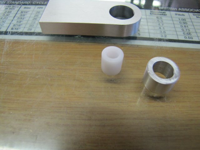
The PTFE bush I did twice; on the first attempt I turned it's OD 0.02mm under the size needed, and that resulted in too light a fit...
The aluminium insert pressed into the big hole:
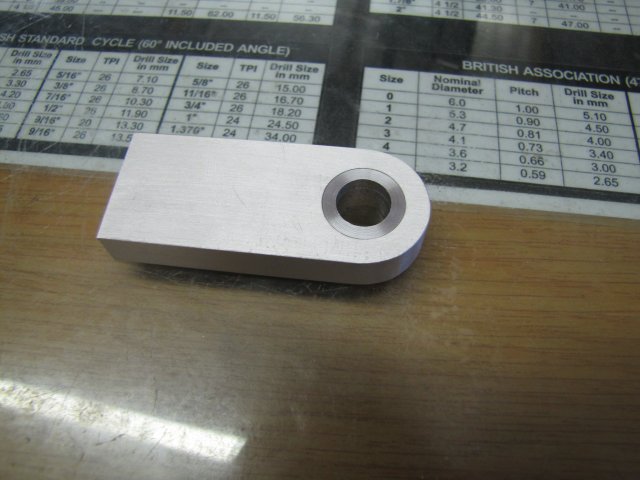
After a bit of filing and emery, the joint is nearly invisible:
You can click the photo above to see a bigger version; there it's more visible.
New bush pressed in - intentionally standing 0.5mm proud on either side of the bearing column:
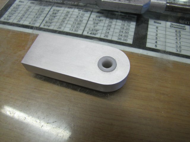
That looks a lot better; in fact, once the flywheel is mounted, the plastic bush will be nearly hidden:
Regards, Arnold
Stole an hour in the shop after work today; decided I'll fix up one of the eye-sores...
I removed the big ugly PTFE bushing from the "thin-shaft-side" bearing column, and turned up an aluminium filler piece and smaller PTFE bush, all for press fits:
The PTFE bush I did twice; on the first attempt I turned it's OD 0.02mm under the size needed, and that resulted in too light a fit...
The aluminium insert pressed into the big hole:
After a bit of filing and emery, the joint is nearly invisible:
You can click the photo above to see a bigger version; there it's more visible.
New bush pressed in - intentionally standing 0.5mm proud on either side of the bearing column:
That looks a lot better; in fact, once the flywheel is mounted, the plastic bush will be nearly hidden:
Regards, Arnold
Well your terrible, just terrible. Now I'm hooked, starting a sketch up of something to build. I don't think I can wing the Comber with what I have to work with and still keep my brain cell intact, but something close.
Gone some thirty days now with no smoking so its about time I started on something that will give me items to throw
Like Plato? try Kafka
Robert
Gone some thirty days now with no smoking so its about time I started on something that will give me items to throw
Like Plato? try Kafka
Robert
arnoldb
Well-Known Member
- Joined
- Apr 8, 2009
- Messages
- 1,792
- Reaction score
- 12
:big: :big: Thanks Robert - I'll take that as a huge compliment ;D - I never knew "terrible" and "passionate" were synonyms :big:. You're thirty days plus ahead of me then... I need to quit as well, but I'm scared of what will happen to my boss and assistant...........
Today's bit; I had a good shop session, so lots of photos...
I started work on the piston. Earlier in the build, I left the bore of the cylinder just a tad under the 16mm I wanted. That was on purpose; I have some 16mm round brass bar to make the piston from, but it needs a bit of skimming, so will end up under 16mm. I chucked the brass bar up in the collet chuck on the lathe, and faced it and then parted it down part-way on 5mm length:
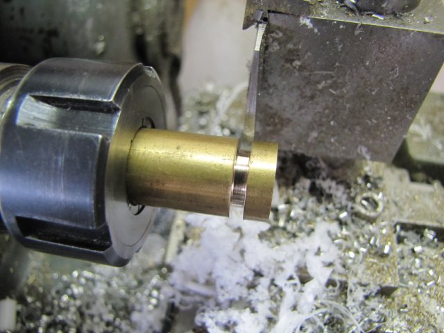
Starting with a partial parting cut might seem silly, but there's a reason for it. If you look closely at the above photo, you'll see the burrs raised on both sides of the parting cut. If I left this for last, that would leave a ridge on the piston that I'd have to remove in some or other fashion - and there's no easy or accurate way.
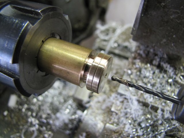
A little later, and I'd used a small file to put chamfers on both sides of the piston, a free-hand oil groove with a triangular needle file, then turned it to final size and drilled it 2mm through the center:
After finishing the parting cut, I ended up with this:
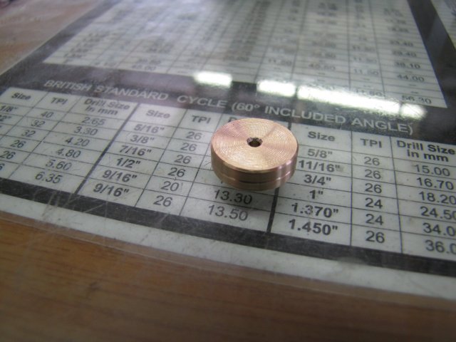
The face shown is on the parted-off side; I still need to practice parting a lot more to get better finishes. The pronounced countersink on the hole was added manually; on both sides of the piston; these are needed for later steps.
Next I started on the forks. Drilled a 1.6mm hole through some 6mm thick square brass:
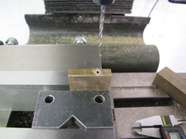
Then I mounted the slitting saw on the mill and used my height gauge to pick up the top of the block and set the slitting saw to height:
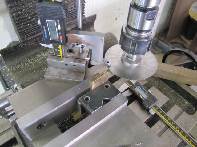
I just used my 0.5mm slitting saw to slit through for the fork bodies deep enough to later cut them off. Then added my 1mm slitting saw to the arbour to start cutting the forks - using the height gauge again - this left a 1.5mm wide slot; which I just slit to depth on the line I'd marked:
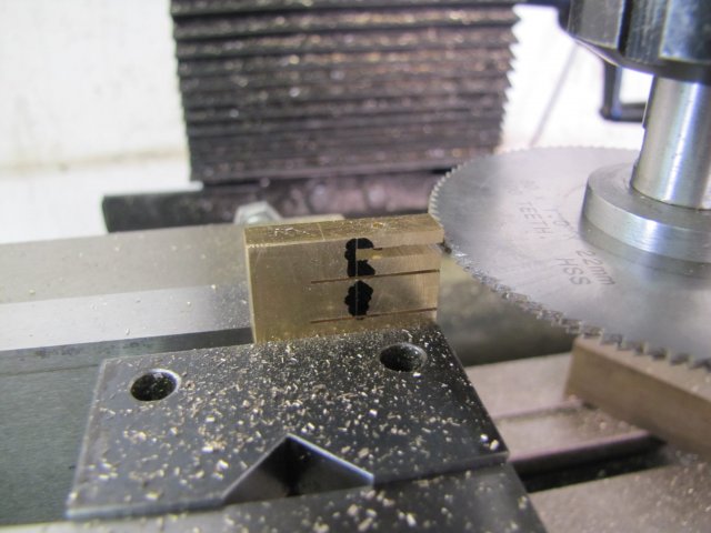
I then moved the mill quill down by 1mm, and slit again - leaving a 2.5mm wide slot, and then moved down and repeated:
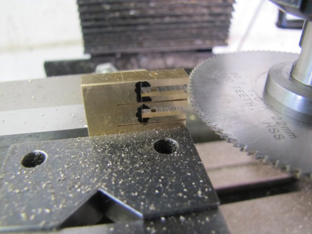
If you look carefully, you'll see there's two stilling saws ganged together; a 1mm and a 0.5mm one. I really need to buy more slitting saws :big:
The block was then flipped in the vise and clamped down with a generous bit of cardboard to prevent things moving, and then the two forks slit off from the parent stock:
I then drilled the backs of the workpieces 1.6mm to tap M2 later:
After tapping and then some free-hand filing to round over the ends, the forks were done:
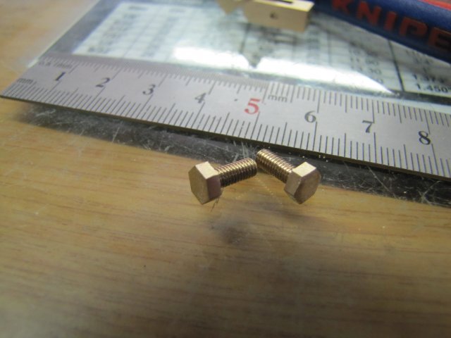
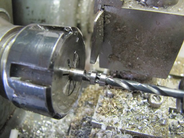
I needed some bolts to hold the cam to the base. Any old 3mm screw would have done, but I rather made my own. Here's some 5mm hex brass turned down and threaded with the tailstock die holder:
After some more machining, I had these:
The cylinder block needed some holes plugged - just two bits of 2mm brazing rod plugged in with high-strength retaining compound:
Ugly, innit ? ;D
Some more 2mm brazing rod followed to make the connecting rod; threaded both ends M2 to fit the forks and lock nuts. The piston have to be soldered on in the middle:
I used some aluminium drinks-can plate to clamp down the connecting rod with the piston in place. The plate keeps the piston on the correct height and prevents the vise from marring the connecting rod. Any solder that leaks through won't stick to the aluminium plate either:
Some soft-solder flux was brushed on before assembly, then I soldered the lot together with some electronics solder. I just used a small plumber's blow-torch to heat things up. It looks horrible here, but worked quite well:
Remember the chamfers I mentioned on the piston earlier on? - This is where they came into play; I made the hole in the piston a relatively tight fit to the connecting rod, but they had to be soldered together, and with the hole being tight the solder would not flow through. The chamfers provide the necessary area for the solder to make a reasonable secure joint.
Next I cleaned up some 6mm silver steel rod and drilled it through and reamed to 4mm, and parted off two rings 2.4mm thick:
Some brass followed, a tad under 4mm OD for a smooth running fit in the silver steel above, and parted off at 2.5mm lengths:
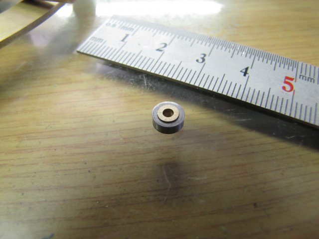
Makes for some OK bearings:
A quick trial-fit in the cam, and I could see how much to adjust the forks in the connecting rod:
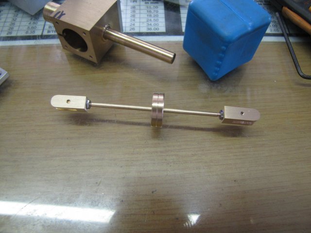
All assembled together:
Please excuse all the oily marks and so on; when I assemble something for the first time, I use a LOT of oil. As can be seen from the photo, I''d also filed down and smoothed over the plugs on the air passages to blend in to the main shaft
There was a couple of tight spots on the cam with things all assembled; that was easily taken care of with some light filing and emery paper.
Things turned over fairly smoothly after that by hand, but wouldn't give me the easy flick with multiple rotations... and I was NOT happy; I'd built this engine so far to be EASY to run!
It was supposed to spin like a top...
At this point Thor threw a hammer at me noggin, and connected... HARD... ; Well, DUHHH - I've not yet drilled the main bearing column for an air supply or exhaust... - There is nowhere for the cylinder to suck or vent... So obviously it would not run well :big:- It needs a bit of breathing :big:
Today's bit; I had a good shop session, so lots of photos...
I started work on the piston. Earlier in the build, I left the bore of the cylinder just a tad under the 16mm I wanted. That was on purpose; I have some 16mm round brass bar to make the piston from, but it needs a bit of skimming, so will end up under 16mm. I chucked the brass bar up in the collet chuck on the lathe, and faced it and then parted it down part-way on 5mm length:
Starting with a partial parting cut might seem silly, but there's a reason for it. If you look closely at the above photo, you'll see the burrs raised on both sides of the parting cut. If I left this for last, that would leave a ridge on the piston that I'd have to remove in some or other fashion - and there's no easy or accurate way.
A little later, and I'd used a small file to put chamfers on both sides of the piston, a free-hand oil groove with a triangular needle file, then turned it to final size and drilled it 2mm through the center:
After finishing the parting cut, I ended up with this:
The face shown is on the parted-off side; I still need to practice parting a lot more to get better finishes. The pronounced countersink on the hole was added manually; on both sides of the piston; these are needed for later steps.
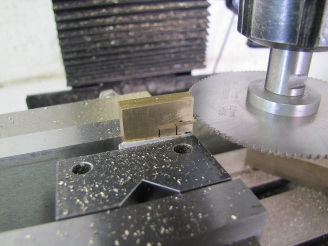
Next I started on the forks. Drilled a 1.6mm hole through some 6mm thick square brass:
Then I mounted the slitting saw on the mill and used my height gauge to pick up the top of the block and set the slitting saw to height:
I just used my 0.5mm slitting saw to slit through for the fork bodies deep enough to later cut them off. Then added my 1mm slitting saw to the arbour to start cutting the forks - using the height gauge again - this left a 1.5mm wide slot; which I just slit to depth on the line I'd marked:
I then moved the mill quill down by 1mm, and slit again - leaving a 2.5mm wide slot, and then moved down and repeated:
If you look carefully, you'll see there's two stilling saws ganged together; a 1mm and a 0.5mm one. I really need to buy more slitting saws :big:
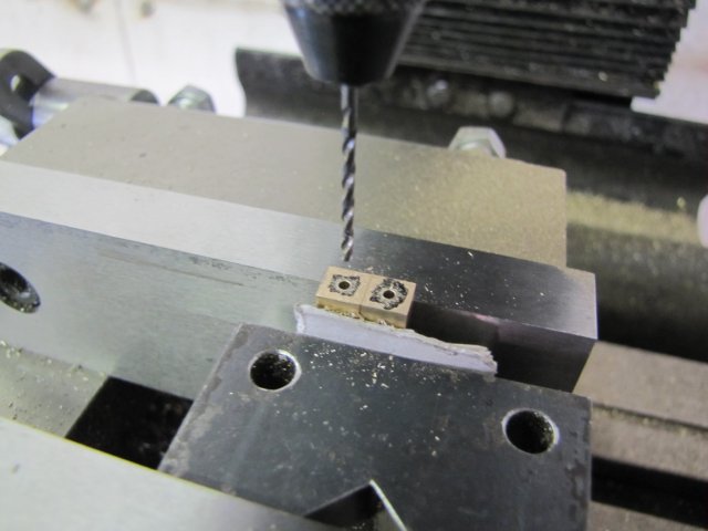
The block was then flipped in the vise and clamped down with a generous bit of cardboard to prevent things moving, and then the two forks slit off from the parent stock:
I then drilled the backs of the workpieces 1.6mm to tap M2 later:
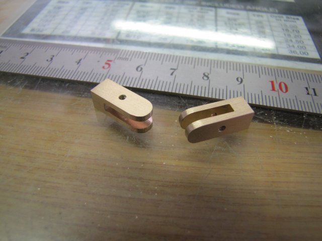
After tapping and then some free-hand filing to round over the ends, the forks were done:
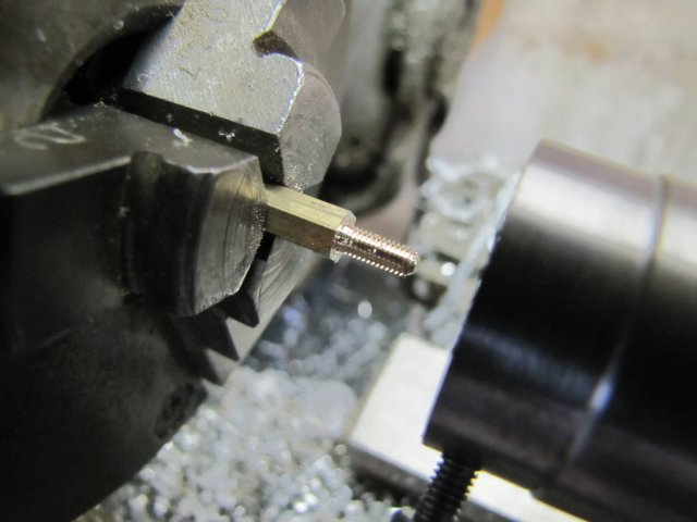
I needed some bolts to hold the cam to the base. Any old 3mm screw would have done, but I rather made my own. Here's some 5mm hex brass turned down and threaded with the tailstock die holder:
After some more machining, I had these:
The cylinder block needed some holes plugged - just two bits of 2mm brazing rod plugged in with high-strength retaining compound:
Ugly, innit ? ;D
Some more 2mm brazing rod followed to make the connecting rod; threaded both ends M2 to fit the forks and lock nuts. The piston have to be soldered on in the middle:
I used some aluminium drinks-can plate to clamp down the connecting rod with the piston in place. The plate keeps the piston on the correct height and prevents the vise from marring the connecting rod. Any solder that leaks through won't stick to the aluminium plate either:
Some soft-solder flux was brushed on before assembly, then I soldered the lot together with some electronics solder. I just used a small plumber's blow-torch to heat things up. It looks horrible here, but worked quite well:
Remember the chamfers I mentioned on the piston earlier on? - This is where they came into play; I made the hole in the piston a relatively tight fit to the connecting rod, but they had to be soldered together, and with the hole being tight the solder would not flow through. The chamfers provide the necessary area for the solder to make a reasonable secure joint.
Next I cleaned up some 6mm silver steel rod and drilled it through and reamed to 4mm, and parted off two rings 2.4mm thick:
Some brass followed, a tad under 4mm OD for a smooth running fit in the silver steel above, and parted off at 2.5mm lengths:
Makes for some OK bearings:
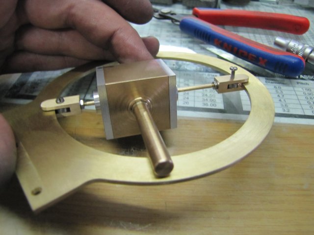
A quick trial-fit in the cam, and I could see how much to adjust the forks in the connecting rod:
All assembled together:
Please excuse all the oily marks and so on; when I assemble something for the first time, I use a LOT of oil. As can be seen from the photo, I''d also filed down and smoothed over the plugs on the air passages to blend in to the main shaft
There was a couple of tight spots on the cam with things all assembled; that was easily taken care of with some light filing and emery paper.
Things turned over fairly smoothly after that by hand, but wouldn't give me the easy flick with multiple rotations... and I was NOT happy; I'd built this engine so far to be EASY to run!
It was supposed to spin like a top...
At this point Thor threw a hammer at me noggin, and connected... HARD... ; Well, DUHHH - I've not yet drilled the main bearing column for an air supply or exhaust... - There is nowhere for the cylinder to suck or vent... So obviously it would not run well :big:- It needs a bit of breathing :big:
arnoldb
Well-Known Member
- Joined
- Apr 8, 2009
- Messages
- 1,792
- Reaction score
- 12
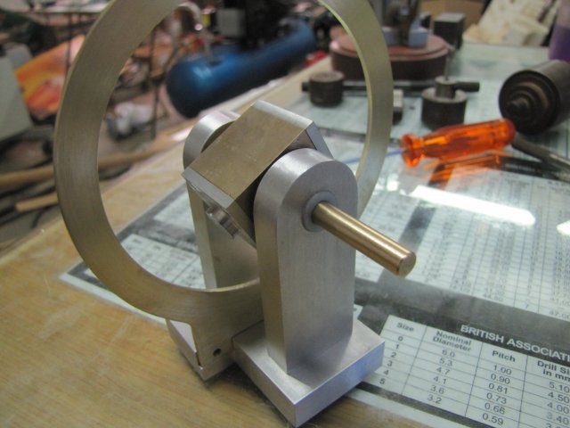
Thanks Brock - the cam ring isn't really difficult - just a bit time consuming. It's a worthwhile engine to build; videos doesn't really do it justice - it has to be seen first-hand
I didn't get a lot done today, but had quite a bit of fun ;D
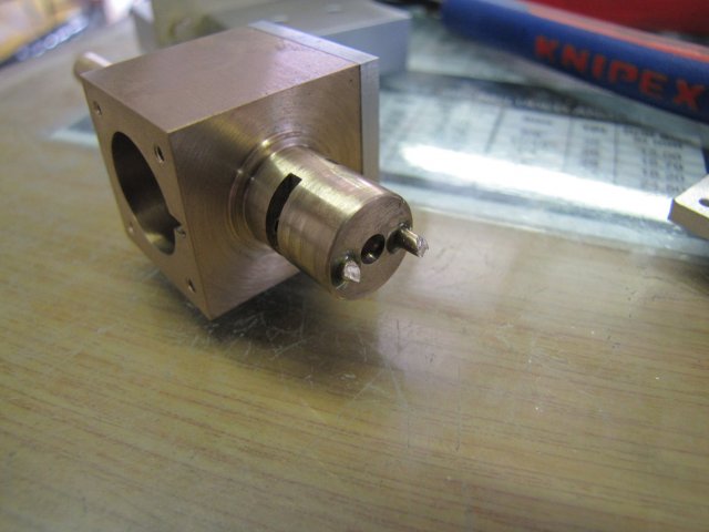
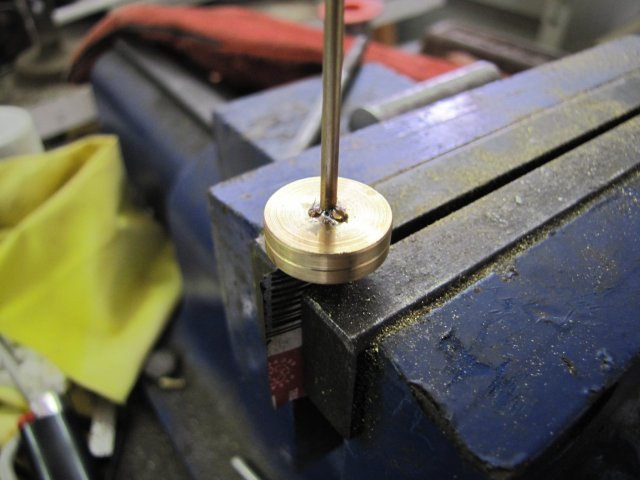
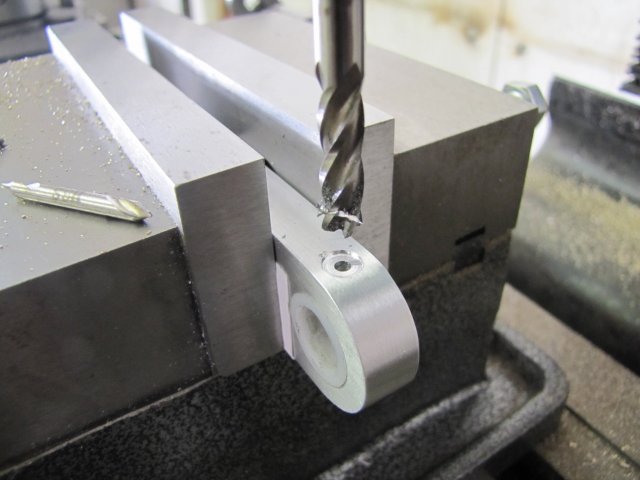
First I drilled the column for the port holes - just 2.5mm straight through the center through both sides. One side will be tapped M3 for the airline connection, and I used a 6mm end mill to make a flat for the connector to screw up to:
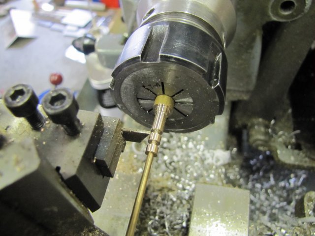
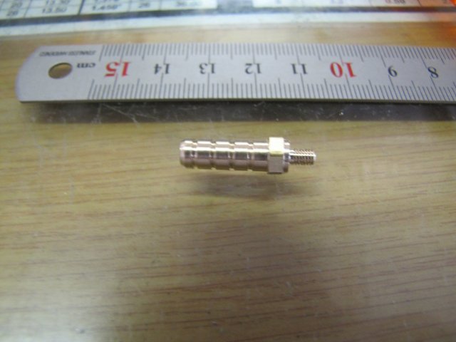
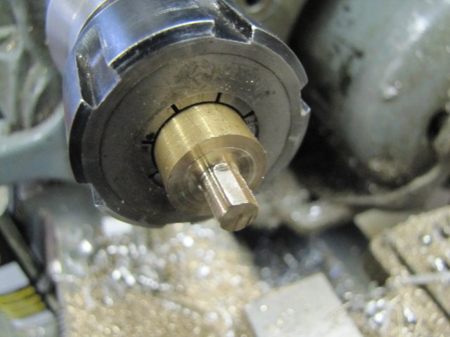
Then I turned up the airline connector from some 6mm hex brass:
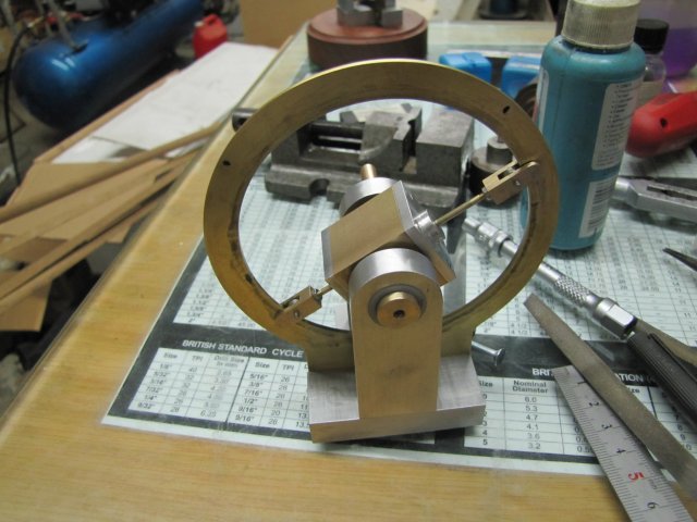
And then the real fun started; everything except the flywheel was there to give the engine a test run - so I tried it ;D:
[ame]http://www.youtube.com/watch?v=jHJ0YAyGoA4[/ame]
woohoo1 - I didn't even know if it would run after all the changes I made.
I borrowed the flywheel off my grasshopper engine, and added that; after about 10 minutes of running, it could do slow too:
[ame]http://www.youtube.com/watch?v=gSra3sXZQoE[/ame]
It's not quite running on breath power; an almighty blow gets me a couple of turns, but I think I can get it running as I want with a slightly bigger diameter flywheel with most of the weight in the rim and some additional run-in time.
So, it's flywheel, wooden base and final cleanup to go now...
Regards, Arnold
- the cam ring isn't really difficult - just a bit time consuming. It's a worthwhile engine to build; videos doesn't really do it justice - it has to be seen first-hand I didn't get a lot done today, but had quite a bit of fun ;D
First I drilled the column for the port holes - just 2.5mm straight through the center through both sides. One side will be tapped M3 for the airline connection, and I used a 6mm end mill to make a flat for the connector to screw up to:
Then I turned up the airline connector from some 6mm hex brass:
And then the real fun started; everything except the flywheel was there to give the engine a test run - so I tried it ;D:
[ame]http://www.youtube.com/watch?v=jHJ0YAyGoA4[/ame]
woohoo1 - I didn't even know if it would run after all the changes I made.
I borrowed the flywheel off my grasshopper engine, and added that; after about 10 minutes of running, it could do slow too:
[ame]http://www.youtube.com/watch?v=gSra3sXZQoE[/ame]
It's not quite running on breath power; an almighty blow gets me a couple of turns, but I think I can get it running as I want with a slightly bigger diameter flywheel with most of the weight in the rim and some additional run-in time.
So, it's flywheel, wooden base and final cleanup to go now...
Regards, Arnold
You never cease to amaze.
I haven't even finished sketching up the gizmo to be my next project.
Really is a nice looking engine you built.
Robert
I haven't even finished sketching up the gizmo to be my next project.
Really is a nice looking engine you built.
Robert
arnoldb
Well-Known Member
- Joined
- Apr 8, 2009
- Messages
- 1,792
- Reaction score
- 12
Thanks Robert - I'll give you a bit of a break then; I'm waiting to get some stock to make the flywheel from
Dave, thank you Thm: - yes... Checking those seals... I might start believing it Rof}
Andrew, thanks I hope she will like it ;D. It just takes a bit of effort to make it look easy; anybody can do it ;D
Thanks Danstir - there's some more to come.
Chuck, thank you I think a two cylinder is doable and should be a very nice runner.
The biggest problem would be the valve porting... the easiest way would be to have ports in both bearing columns feeding the pistons in parallel, with the the second cam offset at 90 degrees. The cams can be machined in one go with two plates clamped together, so that will not take much more time to do. A very interesting thought!
Regards, Arnold
- I'll give you a bit of a break then; I'm waiting to get some stock to make the flywheel from Dave, thank you Thm: - yes... Checking those seals... I might start believing it Rof}
Andrew, thanks
I hope she will like it ;D. It just takes a bit of effort to make it look easy; anybody can do it ;DThanks Danstir
- there's some more to come.Chuck, thank you
I think a two cylinder is doable and should be a very nice runner.The biggest problem would be the valve porting... the easiest way would be to have ports in both bearing columns feeding the pistons in parallel, with the the second cam offset at 90 degrees. The cams can be machined in one go with two plates clamped together, so that will not take much more time to do. A very interesting thought!
Regards, Arnold
arnoldb
Well-Known Member
- Joined
- Apr 8, 2009
- Messages
- 1,792
- Reaction score
- 12
I didn't post yesterday's work, as a social commitment yesterday evening interfered :big:
Work started on the flywheel.
I got a phosphor bronze off-cut from one of my suppliers - not cheap, but it was the best I could do:
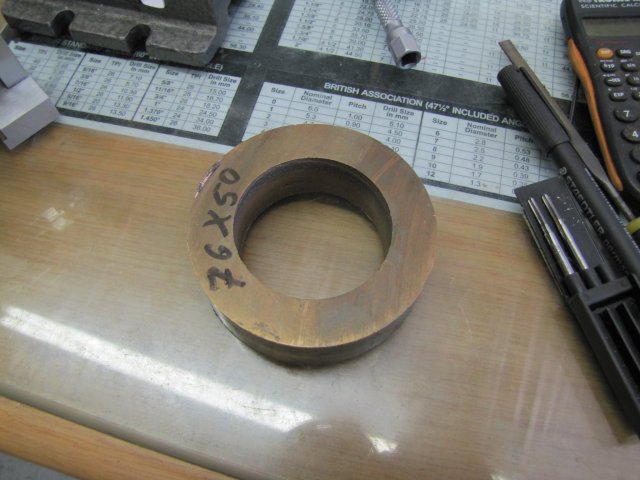
Started cleaning it up; this piece is just long enough to make two flywheels from. I've machined quite a bit of PB so far - always without any problems, but this piece was giving me some grief; it had soft and hard spots in it and was a bear to turn:
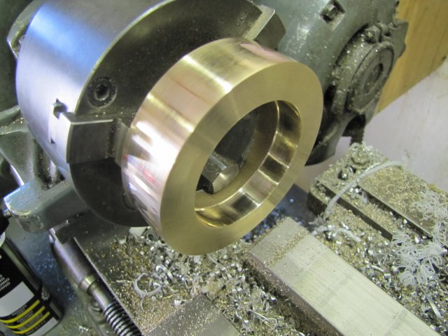
Parting it off was no fun; my rear parting tool wouldn't touch it, even though I'd honed it up super sharp! So I tried my old jig-saw parting bit and that ran through it without any problems:
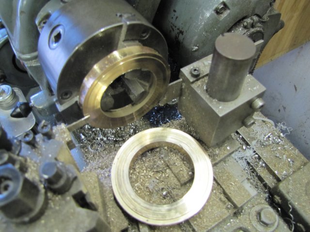
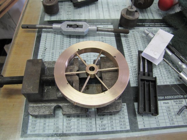
After some more turning, I had the flywheel rim:

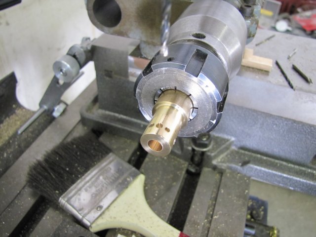
Next I turned up the flywheel hub, and drilled six 2mm holes in it for spokes, and a 2.5mm hole between two spoke locations to tap M3 for a grub screw:
While I had the dividing head mounted on the mill, I also drilled the rim for the spokes. The hard and soft spots made the drill wander quite a bit in each hole...
Spokes were cut from 2mm brazing rod, and one end of each cleaned up with a file:
The wandering of the drill in the rim made for a tight fit for the spokes through the rim; I had to resort to a small hammer to tap them in to just outside of the hub's radius. Then I set the hub on a piece of 6mm rod in the tailstock to help with positioning:
I put a drop of retainer in each hole in the hub, and also on the bits of the spokes still sitting outside the hub. Then I tapped each spoke in. I then moved away the tailstock, and with the rod left in the hub, I clocked the hub as center as I could by lightly tapping the bits of spoke still sticking out of the rim. Because the holes through the rim had wandered, axial run-out would have caused a very wobbly flywheel - so I checked further away as well, and used the rod to bend the spokes slightly to get the wobble out:
The flywheel was then set aside to let the retainer cure overnight. The spokes need to be filed or turned down later:
On to some woodwork...
Earlier this year while visiting, my father brought me a circular saw and a mounting table that my grandfather had very generously donated to me:
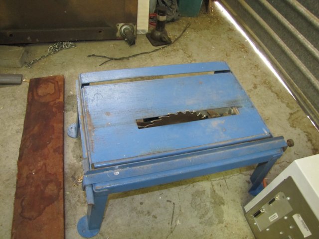
I haven't used it yet as I steer away from woodwork in general, but now was the time to try it ;D
The piece of teak I have for bases is quite difficult to cut with a jigsaw as I had done in the past - the circular saw did in seconds what used to take me many minutes to get done:
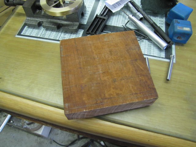
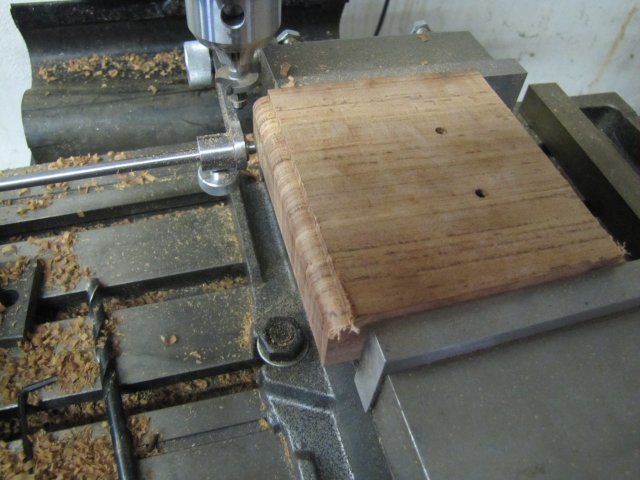
A final cleanup of the uncut edges of the block was done on the mill:
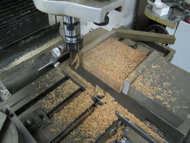
The piece of timber is very rough, and had spent quite a bit of time out-of-doors before I bought it, so all the faces are impregnated with dust and sand, so instead of breaking out the wood plane to plane down the flat faces, I used a very sharp HSS flycutter on the mill:
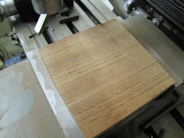
That left a really smooth finish
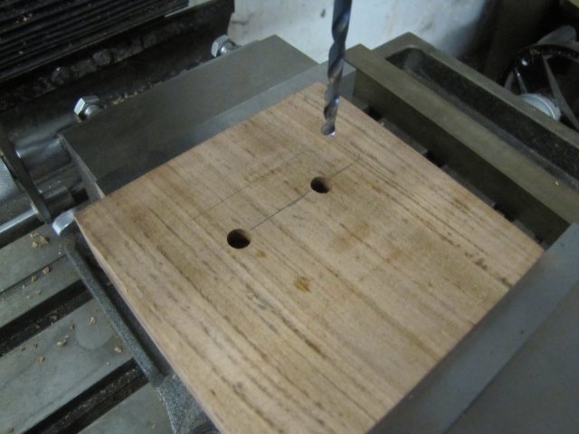
Mounting holes for the engine base was drilled - part-way 8mm and then 4mm through - to match some M4 countersink screws I have:
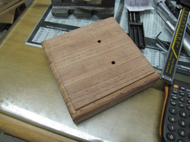
I used a router bit to add a bit of detail - first on both cross-grain faces:
As can be seen in the photo above, the cross grain faces splintered out a bit, but the splintered bits are in areas that would be removed when routing along the grain - without additional splinters coming off.
After a final bit of work with sand paper, the base was looking OK:
I then lavishly applied furniture wax to it, and set it in the sun to have the wax draw into the wood a bit.
Work stopped there for yesterday - I'll carry on in another post for today's bit; have to finish uploading some things.
Regards, Arnold
Work started on the flywheel.
I got a phosphor bronze off-cut from one of my suppliers - not cheap, but it was the best I could do:
Started cleaning it up; this piece is just long enough to make two flywheels from. I've machined quite a bit of PB so far - always without any problems, but this piece was giving me some grief; it had soft and hard spots in it and was a bear to turn:
Parting it off was no fun; my rear parting tool wouldn't touch it, even though I'd honed it up super sharp! So I tried my old jig-saw parting bit and that ran through it without any problems:
After some more turning, I had the flywheel rim:
Next I turned up the flywheel hub, and drilled six 2mm holes in it for spokes, and a 2.5mm hole between two spoke locations to tap M3 for a grub screw:
While I had the dividing head mounted on the mill, I also drilled the rim for the spokes. The hard and soft spots made the drill wander quite a bit in each hole...
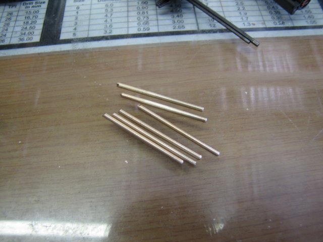
Spokes were cut from 2mm brazing rod, and one end of each cleaned up with a file:
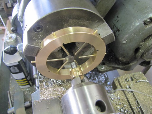
The wandering of the drill in the rim made for a tight fit for the spokes through the rim; I had to resort to a small hammer to tap them in to just outside of the hub's radius. Then I set the hub on a piece of 6mm rod in the tailstock to help with positioning:
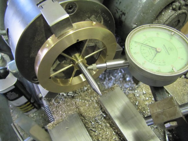
I put a drop of retainer in each hole in the hub, and also on the bits of the spokes still sitting outside the hub. Then I tapped each spoke in. I then moved away the tailstock, and with the rod left in the hub, I clocked the hub as center as I could by lightly tapping the bits of spoke still sticking out of the rim. Because the holes through the rim had wandered, axial run-out would have caused a very wobbly flywheel - so I checked further away as well, and used the rod to bend the spokes slightly to get the wobble out:
The flywheel was then set aside to let the retainer cure overnight. The spokes need to be filed or turned down later:
On to some woodwork...
Earlier this year while visiting, my father brought me a circular saw and a mounting table that my grandfather had very generously donated to me:
I haven't used it yet as I steer away from woodwork in general, but now was the time to try it ;D
The piece of teak I have for bases is quite difficult to cut with a jigsaw as I had done in the past - the circular saw did in seconds what used to take me many minutes to get done:
A final cleanup of the uncut edges of the block was done on the mill:
The piece of timber is very rough, and had spent quite a bit of time out-of-doors before I bought it, so all the faces are impregnated with dust and sand, so instead of breaking out the wood plane to plane down the flat faces, I used a very sharp HSS flycutter on the mill:
That left a really smooth finish
Mounting holes for the engine base was drilled - part-way 8mm and then 4mm through - to match some M4 countersink screws I have:
I used a router bit to add a bit of detail - first on both cross-grain faces:
As can be seen in the photo above, the cross grain faces splintered out a bit, but the splintered bits are in areas that would be removed when routing along the grain - without additional splinters coming off.
After a final bit of work with sand paper, the base was looking OK:
I then lavishly applied furniture wax to it, and set it in the sun to have the wax draw into the wood a bit.
Work stopped there for yesterday - I'll carry on in another post for today's bit; have to finish uploading some things.
Regards, Arnold
arnoldb
Well-Known Member
- Joined
- Apr 8, 2009
- Messages
- 1,792
- Reaction score
- 12
On to today's bit...
The good news is the engine runs, but bad news is there's some of the last machining photos missing, as my camera's batteries gave out after the first photo and the spare set was flat as well :
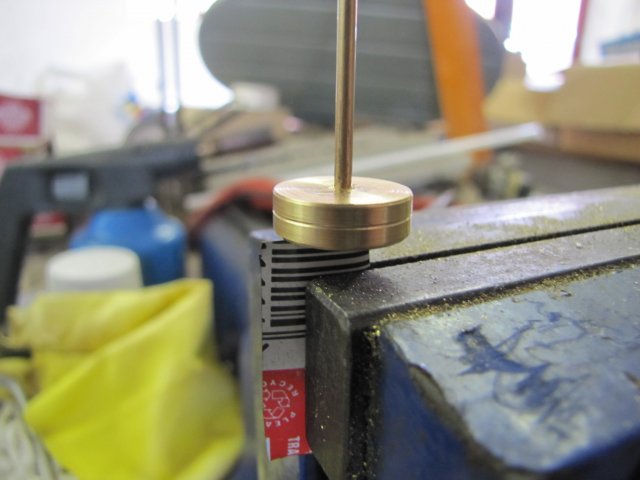
To clean the bits of spoke sticking out of the flywheel, I trimmed them as close as I could with a side-cutter, and turned up a mandrel to mount the flywheel on. I just filed a flat on it for the grub screw to locate on to hold the flywheel in position:
The batteries gave out and was put on charge, so some typing to explain what happened next:
I turned the outside of the flywheel down very carefully - till the spoke ends were off and I then gave it a very light finishing pass across the rim. Even though I worked as carefully as I could, the interrupted cuts and finishing pass brought the rim into a wobble. As I can't fiddle with it too much, I trued it up as well as I could, but it still runs slightly wobbly :-[; I should have silver soldered the spokes in instead of using the retainer.
The waxed wooden base was given a vigorous rubbing with a soft cloth, more wax applied and more buffing with the cloth. I could have painted the base with clear varnish, but I just like the way waxed & polished wood looks, feels and smells - even if it needs a bit of wax every now and then. My sis knows the drill with the floor & furniture wax
I disassembled the engine and gave everything a final clean-over. All the finishes will be left as-is; the engine is fairly big (compared to my other builds) and I think polishing bits of it will be a bit too much on the eye. Also, polished surfaces need attention over time to keep them shiny, and the engine is actually quite delicate - if the cam ring bends slightly or pressure is exerted on the connecting rod or forks, it can go from a good runner to a non-runner in no time.
After cleaning and final assembly (and charged batteries), the engine looks like this:
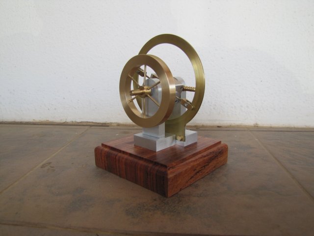
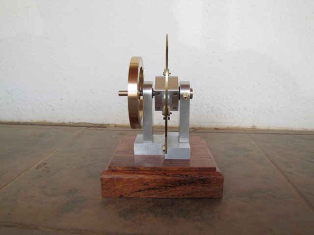
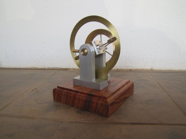
I tried a couple of different locations for taking the finished photos; the above ones were the best lot from the lot, but this one is OK as well:
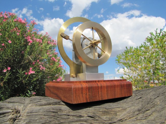
After some oil on the cam; a bit too much : - it still runs very well:
[ame]http://www.youtube.com/watch?v=rqDfsFwSgKI[/ame]
One of the aims of this engine was to have it run on breath power. It does, but still needs a bit more of running in. Please excuse the ugly mug intruding in the scene :big::
[ame]http://www.youtube.com/watch?v=flnqLdfuTIY[/ame]
My sister will hopefully visit in the next couple of weeks, then I can present it to her ;D
Another fun build done... Time to clean the machines, make a bit of tooling, and then on to the next engine.
Regards, Arnold
The good news is the engine runs, but bad news is there's some of the last machining photos missing, as my camera's batteries gave out after the first photo and the spare set was flat as well :
To clean the bits of spoke sticking out of the flywheel, I trimmed them as close as I could with a side-cutter, and turned up a mandrel to mount the flywheel on. I just filed a flat on it for the grub screw to locate on to hold the flywheel in position:
The batteries gave out and was put on charge, so some typing to explain what happened next:
I turned the outside of the flywheel down very carefully - till the spoke ends were off and I then gave it a very light finishing pass across the rim. Even though I worked as carefully as I could, the interrupted cuts and finishing pass brought the rim into a wobble. As I can't fiddle with it too much, I trued it up as well as I could, but it still runs slightly wobbly :-[; I should have silver soldered the spokes in instead of using the retainer.
The waxed wooden base was given a vigorous rubbing with a soft cloth, more wax applied and more buffing with the cloth. I could have painted the base with clear varnish, but I just like the way waxed & polished wood looks, feels and smells - even if it needs a bit of wax every now and then. My sis knows the drill with the floor & furniture wax
I disassembled the engine and gave everything a final clean-over. All the finishes will be left as-is; the engine is fairly big (compared to my other builds) and I think polishing bits of it will be a bit too much on the eye. Also, polished surfaces need attention over time to keep them shiny, and the engine is actually quite delicate - if the cam ring bends slightly or pressure is exerted on the connecting rod or forks, it can go from a good runner to a non-runner in no time.
After cleaning and final assembly (and charged batteries), the engine looks like this:
I tried a couple of different locations for taking the finished photos; the above ones were the best lot from the lot, but this one is OK as well:
After some oil on the cam; a bit too much :
- it still runs very well:[ame]http://www.youtube.com/watch?v=rqDfsFwSgKI[/ame]
One of the aims of this engine was to have it run on breath power. It does, but still needs a bit more of running in. Please excuse the ugly mug intruding in the scene :big::
[ame]http://www.youtube.com/watch?v=flnqLdfuTIY[/ame]
My sister will hopefully visit in the next couple of weeks, then I can present it to her ;D
Another fun build done... Time to clean the machines, make a bit of tooling, and then on to the next engine.
Regards, Arnold
Guess my break is over,
That thing is so cute, running slow sounds like a razor rubbing leather.
Robert
That thing is so cute, running slow sounds like a razor rubbing leather.
Robert
Another wonderful project Arnold, very nicely done indeed.
How long did you manage to stand upright after trying all that lung power?
John
How long did you manage to stand upright after trying all that lung power?
John
arnoldb
Well-Known Member
- Joined
- Apr 8, 2009
- Messages
- 1,792
- Reaction score
- 12
Thanks Robert - You have made some drawings in the meantime Thm:
Jeremy, thanks, and it's a pleasure. Running it on breath power was a bit iffy; I'm surprised as well ;D
Thank you John. :big: I Didn't feel faint at all, so not too bad then.
Kind regards, Arnold
- You have made some drawings in the meantime Thm:Jeremy, thanks, and it's a pleasure
. Running it on breath power was a bit iffy; I'm surprised as well ;DThank you John
. :big: I Didn't feel faint at all, so not too bad then.Kind regards, Arnold