arnoldb
Well-Known Member
- Joined
- Apr 8, 2009
- Messages
- 1,792
- Reaction score
- 12
I mentioned in my tooling log that I'll be starting another "Elmer" build. Besides all the Elmer engines that I still want to build, two needs immediate attention.
The Kimble engine has been nagging at me for a long time; it WANTS to be built, and I will build that one soon, but once again it's on the back-burner...
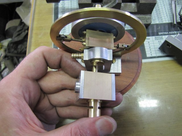
Last year at some point, I was in three minds about which engine to build next for my own collection, and after I showed my sister the pictures, she chose the Elmer #46, which I then built. When I asked her what she wanted for her birthday a couple of months ago, she said I owed her a #46 :big:. Mine is a good runner, and I can just give her this engine, but it does not quite run on breath power, so I thought it better to make her a new one, that will easily run on breath power and with a bit of added personalization. I hope this new build will do the job")
So the rules are "simple" - build a personalized, breath powered, Coomber :big: - I think I'm a sucker for punishment :big:
On to the nitty gritty then...
I'll be building mostly to Elmer's plans except for:
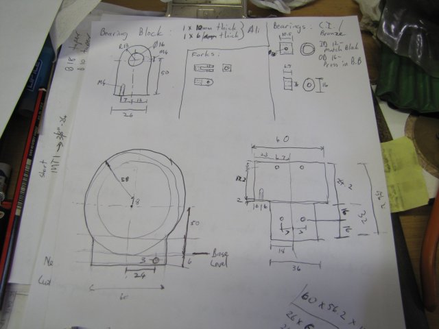
a) Increased cylinder bore size. An increased piston diameter will reduce the pressure needed to power through a stroke. Increasing the bore diameter means increasing the cylinder block dimensions; that means recalculating the bearing block spacings. I'll do that as I go.
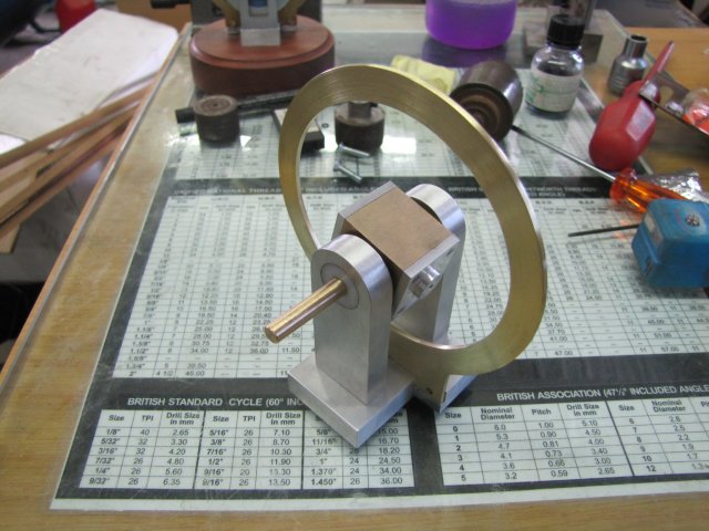
b) A flywheel that is fairly light, yet with good rim mass. Light to keep bearing friction down, and outside rim mass will help it keep up rotational momentum.
c) Minimise friction... My existing Comber has quite a bit of friction in the bearings, and some "slapping" on the cam ring. For this build, I'll add a cast-iron insert on the main/port bearing; the brass running in CI compared to brass in aluminium should be an improvement. For the "slapping", well, I'll just to add a bit more clearance to the forks, make the rollers smoother, and make the cam dead-on smooth. I could add a roller bearing on the non-port bearing block, but maybe a CI insert will do that job as well.
d) Metric - all bits are converted to metric; I don't mind working in inches and fractions and thous, but pretty much everything I have access to is in metric, so I machine in metric.
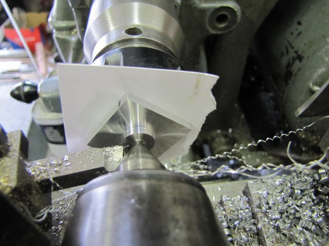
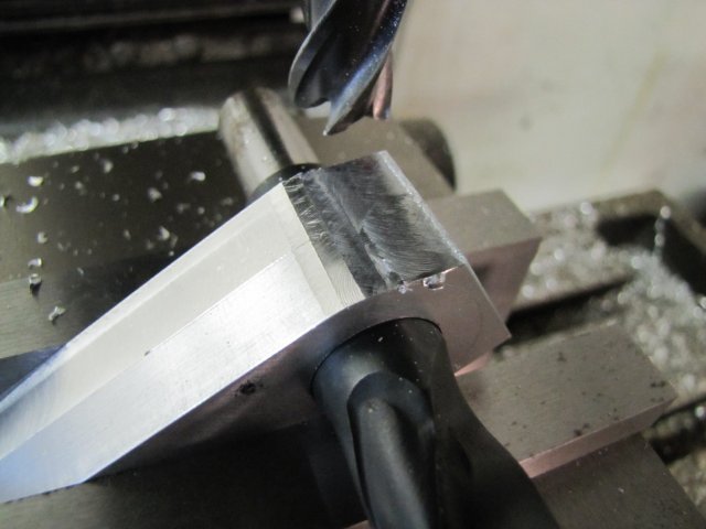
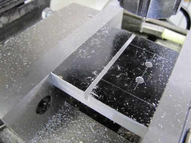
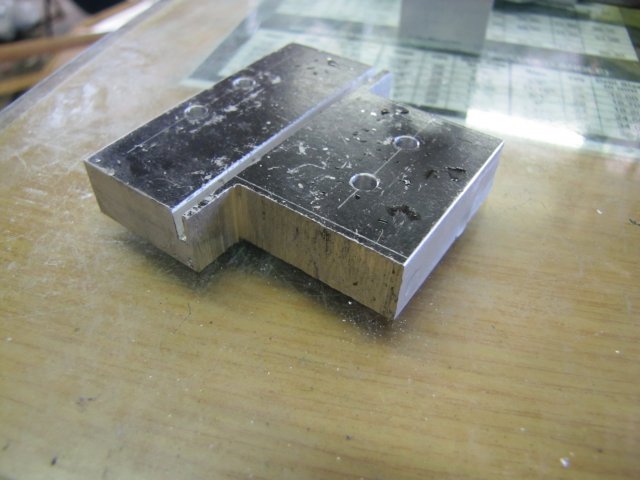
I started off the cylinder block with a bit of 25 x 25 x 40mm brass stock flycut down to get it square:
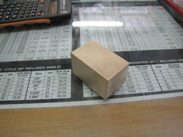
That's the beginnings of the cylinder block.
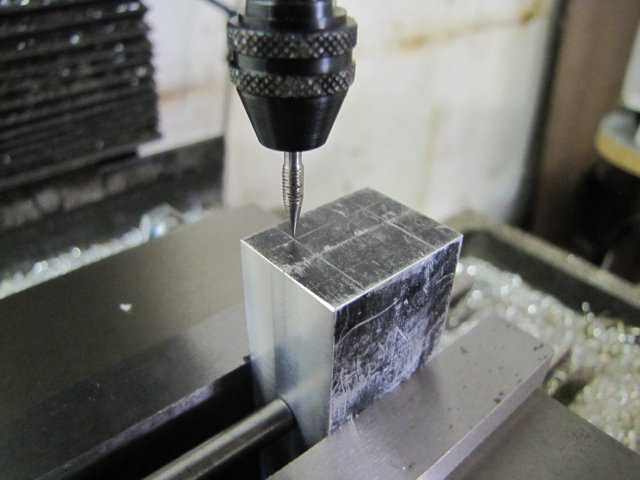
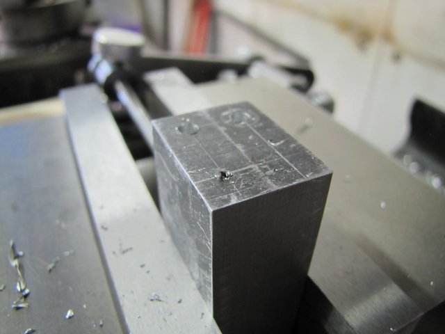
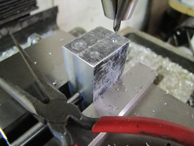
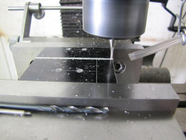
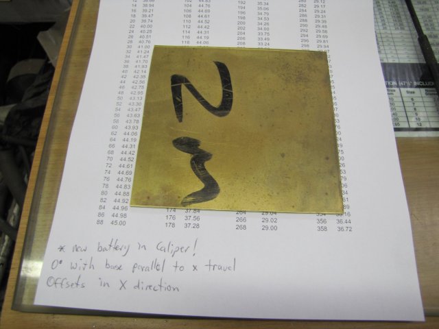
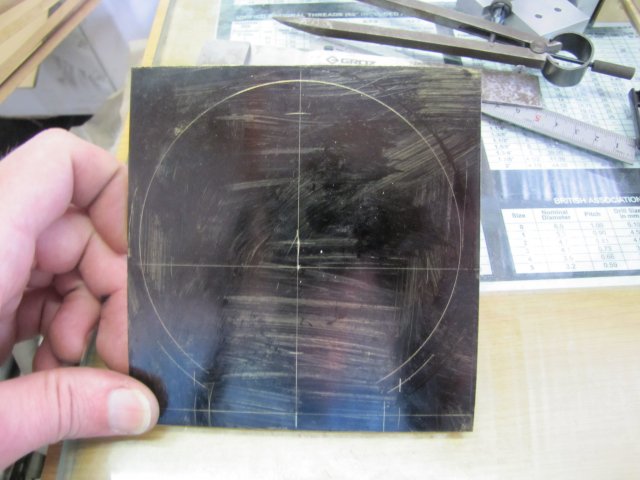
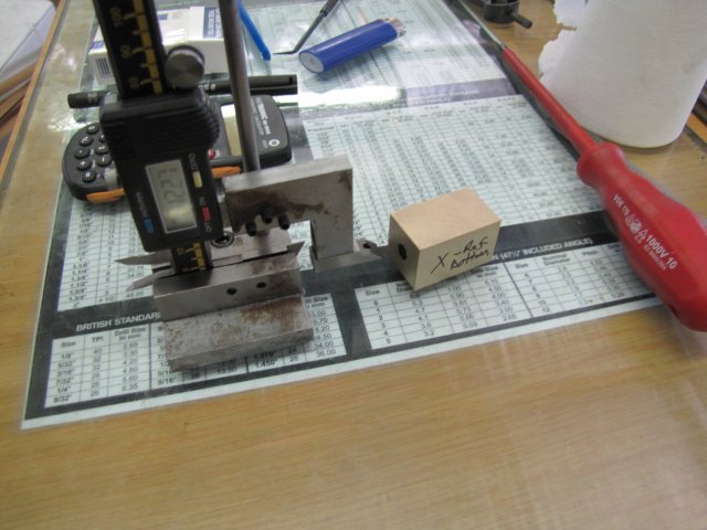
A bit of marking out - to find the center on both of the long-end faces: with two reference sides marked
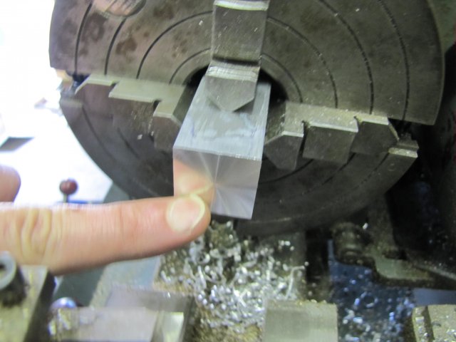
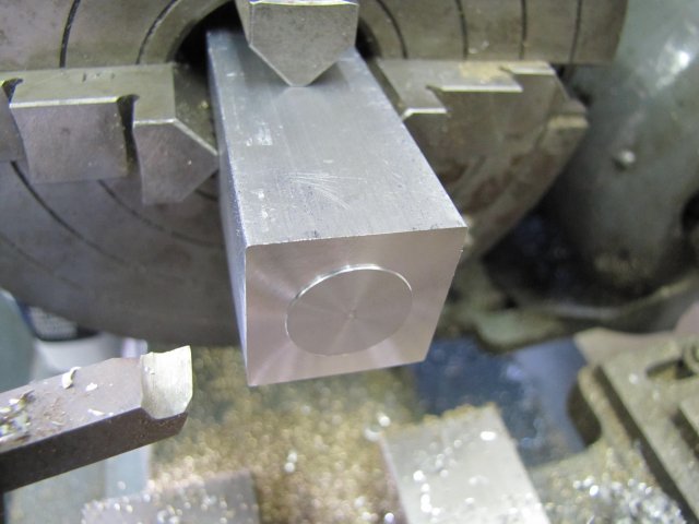
In the 4-jaw chuck on the lathe - finding center with a dead center... I REALLY need to make a proper pump center :big::
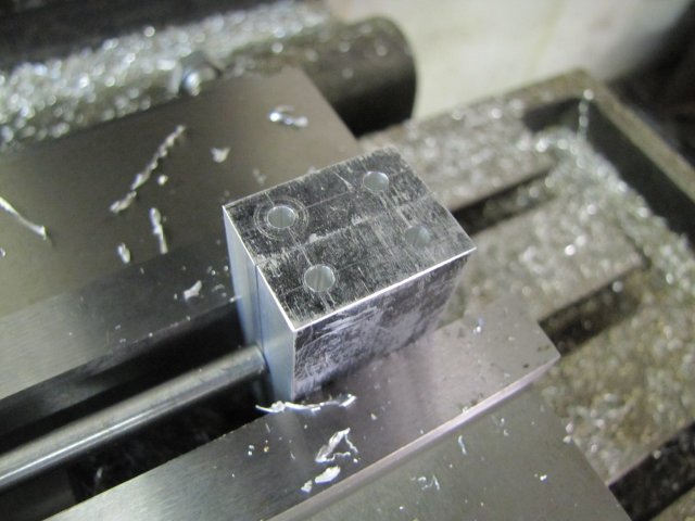
That was then center drilled, reversed in the chuck, and the other end's center found the same way, and drilled 7mm to fit a bit of 7mm round brass I have in stock:

That 7mm brass bar was a fairly tight fit, but as I wanted to silver solder it in there, it needed a bit of clearance for the solder to wick in, so I filed the end of the bar down a bit in the lathe to make it about 0.1mm under-sized, and then knurled the end:
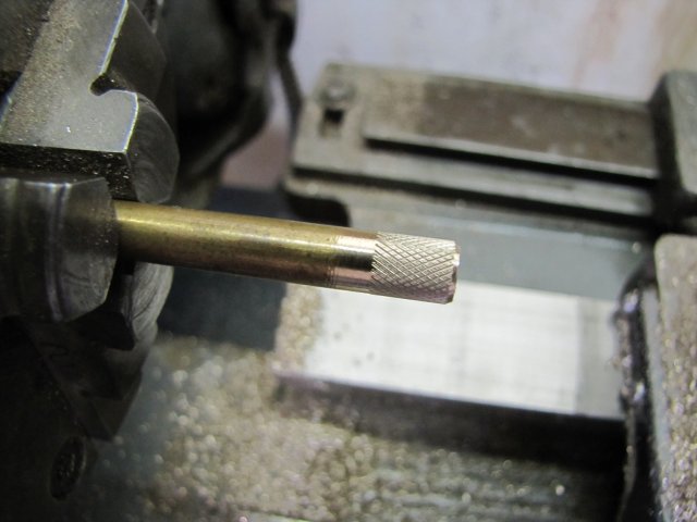
The knurling raises the effective thickness of the brass bar, making it need a good whack to go into the hole in the cylinder block, retaining it fairly straight and square in the hole. It also leaves grooves for the solder to flow (wick) into the joint. I coated the hole inside the cylinder and the knurled bit with silver solder flux paste before whacking together and added a ring of silver solder and additional flux. A bit of "colouring in" with a graphite pencil around that lot followed; the penciled area will prevent flux and silver solder sticking:
Then I showed that lot my Sievert torch - LOTS of heat concentrated on the bottom of the cylinder block to make it glow dull red, took a bit longer than I'm used to; about 50 seconds for the flux to flow (it goes from looking like bubbly sherbet, to white crystals, then like burnt and black caramel, then suddenly like water all over the place) and 10 more for the silver solder to wick in properly, but it came together:
Heat at the bottom of the cylinder, as that draws (wicks) the solder INTO the joint; if you just heat the outside and top, the solder will melt, but not penetrate into the joint.
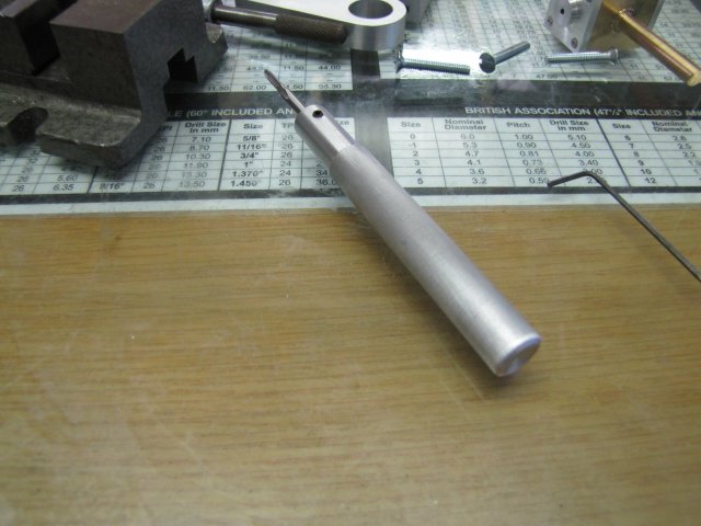
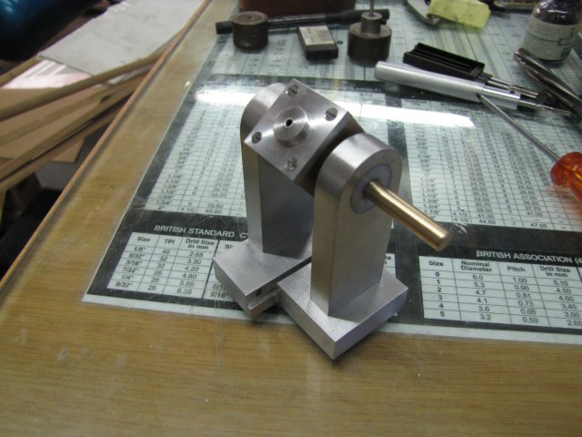
After a pickle in citric acid for the part while I had a bite to eat (~ 30 minutes) I chucked up the 7mm end in the collet chuck on the lathe, and with the tailstock support in the previously-drilled center, I turned down the end to 12mm with a 14mm shoulder:
Flipped in the chuck, and clamping down on the 12mm bit, I VERY carefully turned down the 7mm round bit to 6mm. It has a fair bit of overhang, so a sharp HSS toolbit is the order of the day:
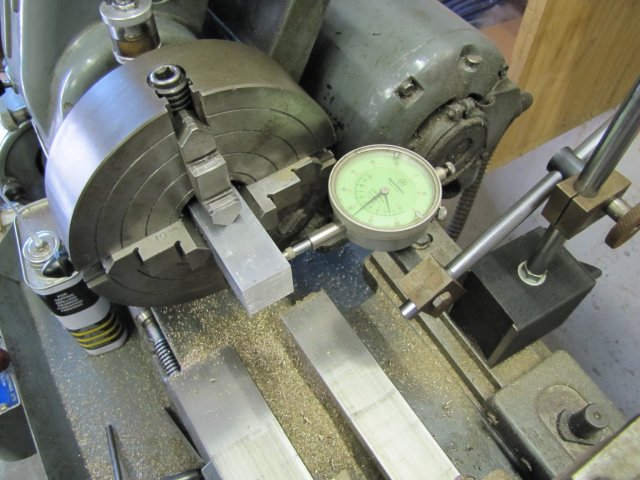
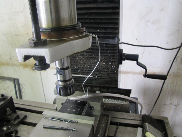
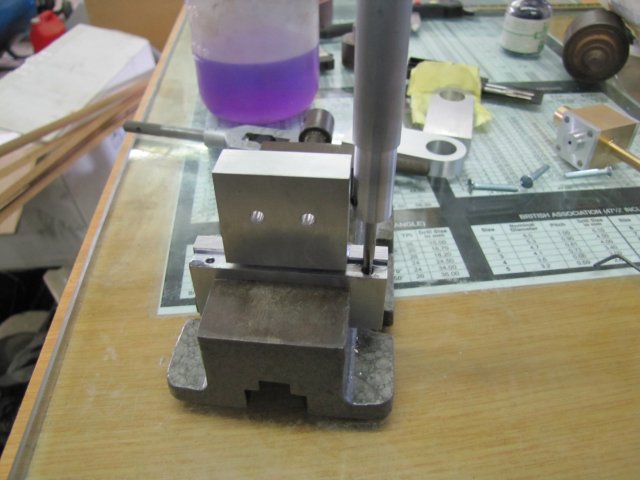
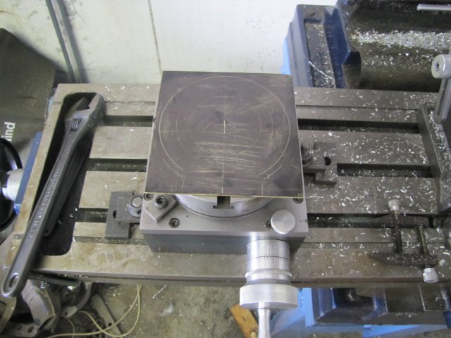
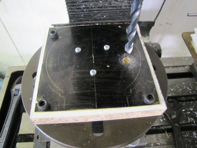
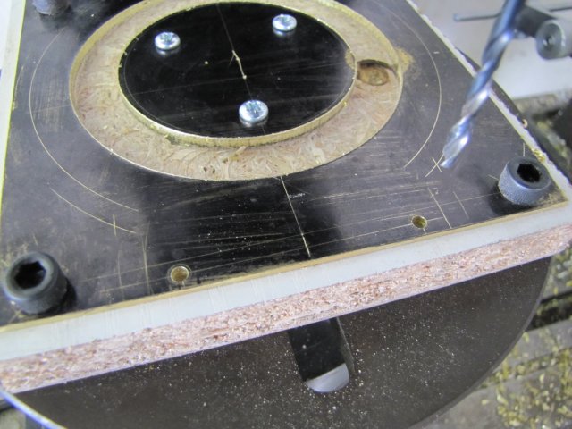
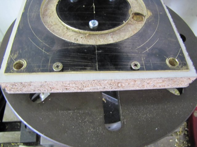
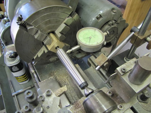
Then I set up that lot in the mill, using a dial test indicator (DTI) to check for squareness. Obviously, the mill needs to be in near-perfect tram for this and the following machining steps:
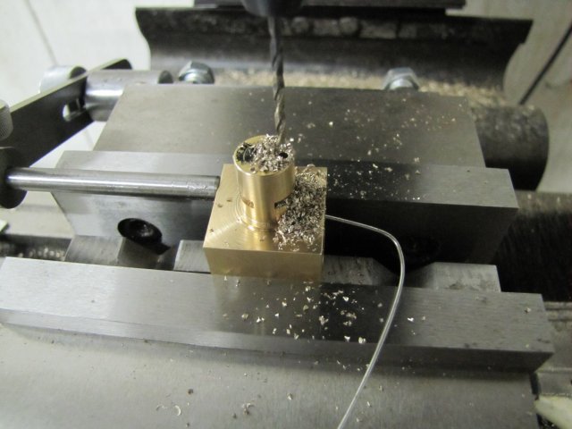
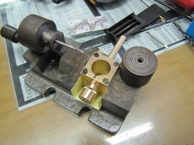
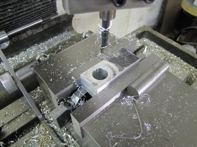
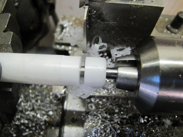
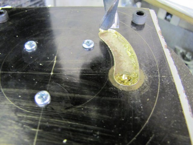
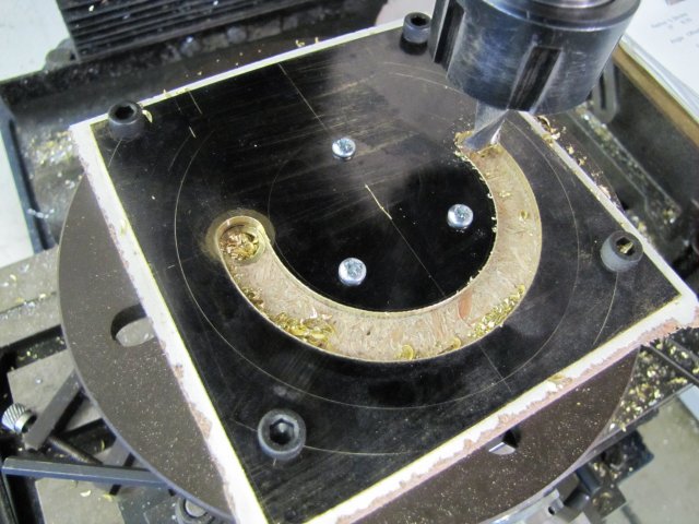
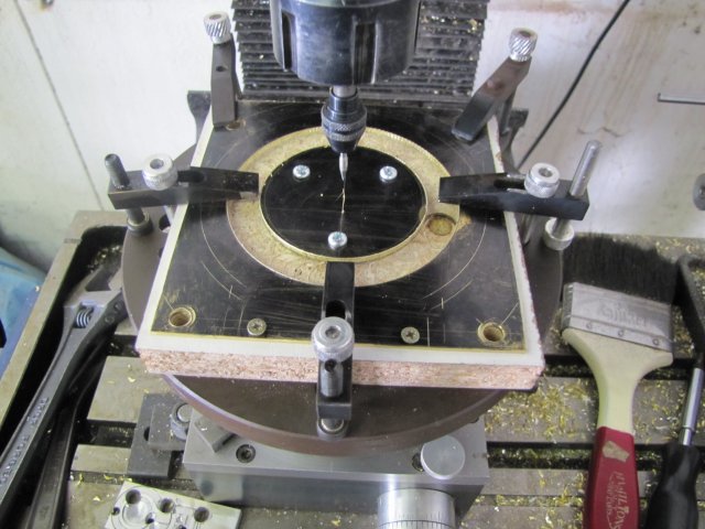
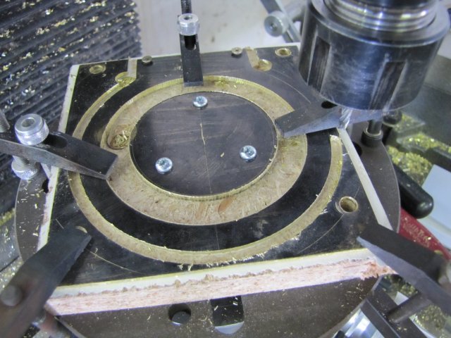
Then I drilled and bored out the cylinder with a couple of successive drill sizes -3mm, 7mm, 13mm and then the boring head to take it up to 16mm. A blurry action photo; as the boring head was running nicely balanced, this shot is at about 800 RPM, and very fuzzy as I was paying more attention to the feed than the camera :big::
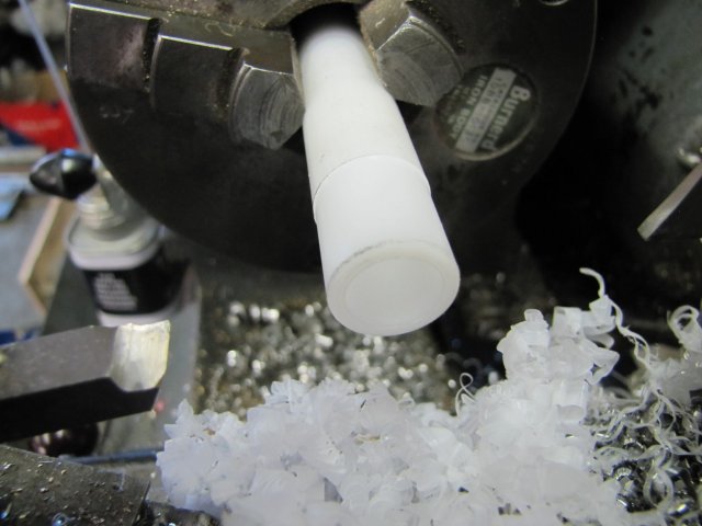
I checked for the final 16mm bore size with a telescoping gauge:
Well, not entirely true... :big: - the sizes measured are all OK, but I know that that digi caliper of mine is inclined to measure 0.05mm under size... - so that hole is actually 15.95mm :big:
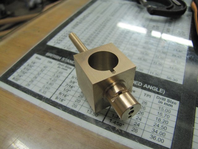
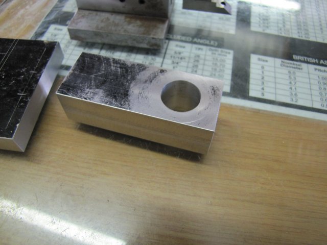
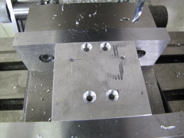
I ended up with this lot for today's work:
If you click on the last photo and have look down the left side of the non-perfect bore, you'll see the slight oval where the shaft joined the body; at least the silver solder job went exactly as planned
I wanted to be a bit further along today, but a neighbour popped in with a a gift and his young 'uns in tow. The gift is a very drinkable bottle of Scotch in return for fixing his wife's treadmill last weekend, and the young 'uns wanted to see some of my engines running. It's just as much fun as machining - if not more so - showing off my simple engines to a four and six year old... They seem to like the Elbow engine , the Comber, and of course the half-finished Cracker... pft pft pft ;D
Kind regards, Arnold
The Kimble engine has been nagging at me for a long time; it WANTS to be built, and I will build that one soon, but once again it's on the back-burner...
Last year at some point, I was in three minds about which engine to build next for my own collection, and after I showed my sister the pictures, she chose the Elmer #46, which I then built. When I asked her what she wanted for her birthday a couple of months ago, she said I owed her a #46 :big:. Mine is a good runner, and I can just give her this engine, but it does not quite run on breath power, so I thought it better to make her a new one, that will easily run on breath power and with a bit of added personalization. I hope this new build will do the job
So the rules are "simple" - build a personalized, breath powered, Coomber :big: - I think I'm a sucker for punishment :big:
On to the nitty gritty then...
I'll be building mostly to Elmer's plans except for:
a) Increased cylinder bore size. An increased piston diameter will reduce the pressure needed to power through a stroke. Increasing the bore diameter means increasing the cylinder block dimensions; that means recalculating the bearing block spacings. I'll do that as I go.
b) A flywheel that is fairly light, yet with good rim mass. Light to keep bearing friction down, and outside rim mass will help it keep up rotational momentum.
c) Minimise friction... My existing Comber has quite a bit of friction in the bearings, and some "slapping" on the cam ring. For this build, I'll add a cast-iron insert on the main/port bearing; the brass running in CI compared to brass in aluminium should be an improvement. For the "slapping", well, I'll just to add a bit more clearance to the forks, make the rollers smoother, and make the cam dead-on smooth. I could add a roller bearing on the non-port bearing block, but maybe a CI insert will do that job as well.
d) Metric - all bits are converted to metric; I don't mind working in inches and fractions and thous, but pretty much everything I have access to is in metric, so I machine in metric.
I started off the cylinder block with a bit of 25 x 25 x 40mm brass stock flycut down to get it square:
That's the beginnings of the cylinder block.
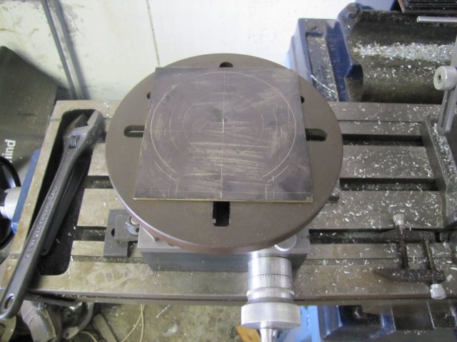
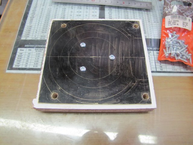
A bit of marking out - to find the center on both of the long-end faces: with two reference sides marked
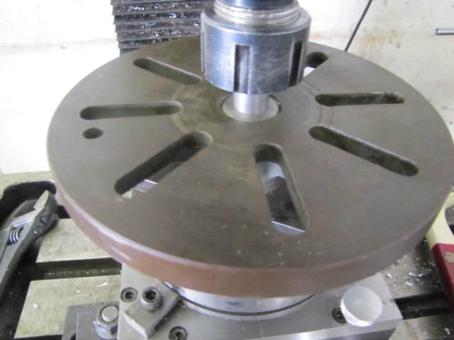
In the 4-jaw chuck on the lathe - finding center with a dead center... I REALLY need to make a proper pump center :big::
That was then center drilled, reversed in the chuck, and the other end's center found the same way, and drilled 7mm to fit a bit of 7mm round brass I have in stock:
That 7mm brass bar was a fairly tight fit, but as I wanted to silver solder it in there, it needed a bit of clearance for the solder to wick in, so I filed the end of the bar down a bit in the lathe to make it about 0.1mm under-sized, and then knurled the end:
The knurling raises the effective thickness of the brass bar, making it need a good whack to go into the hole in the cylinder block, retaining it fairly straight and square in the hole. It also leaves grooves for the solder to flow (wick) into the joint. I coated the hole inside the cylinder and the knurled bit with silver solder flux paste before whacking together and added a ring of silver solder and additional flux. A bit of "colouring in" with a graphite pencil around that lot followed; the penciled area will prevent flux and silver solder sticking:
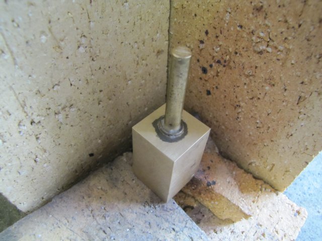
Then I showed that lot my Sievert torch - LOTS of heat concentrated on the bottom of the cylinder block to make it glow dull red, took a bit longer than I'm used to; about 50 seconds for the flux to flow (it goes from looking like bubbly sherbet, to white crystals, then like burnt and black caramel, then suddenly like water all over the place) and 10 more for the silver solder to wick in properly, but it came together:
Heat at the bottom of the cylinder, as that draws (wicks) the solder INTO the joint; if you just heat the outside and top, the solder will melt, but not penetrate into the joint.
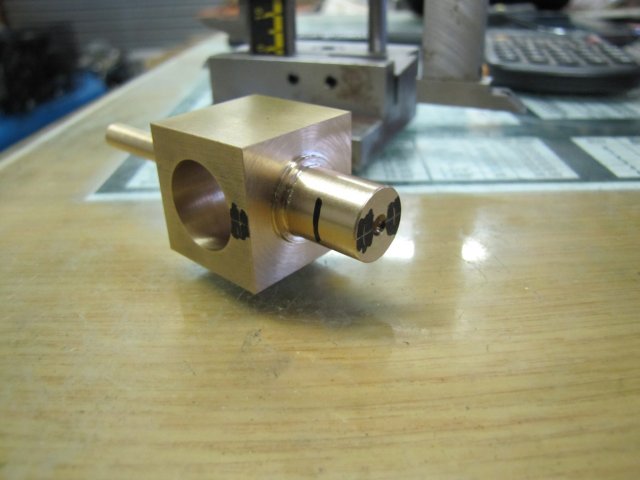
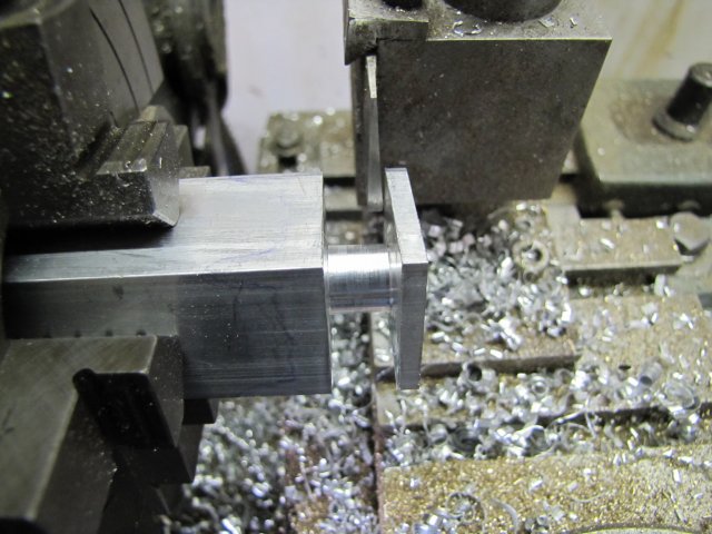
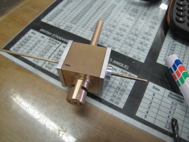
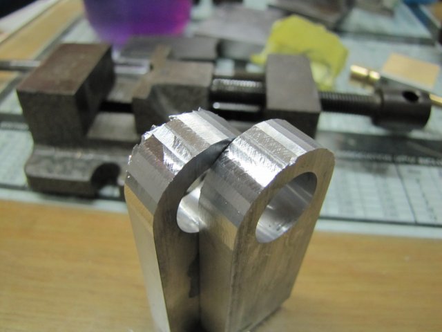
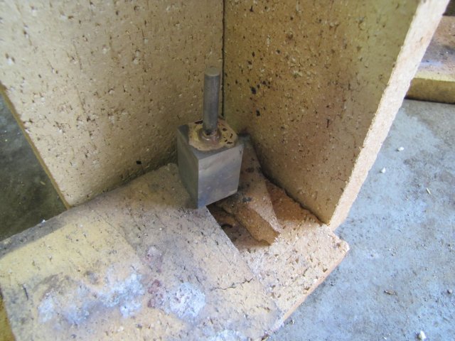
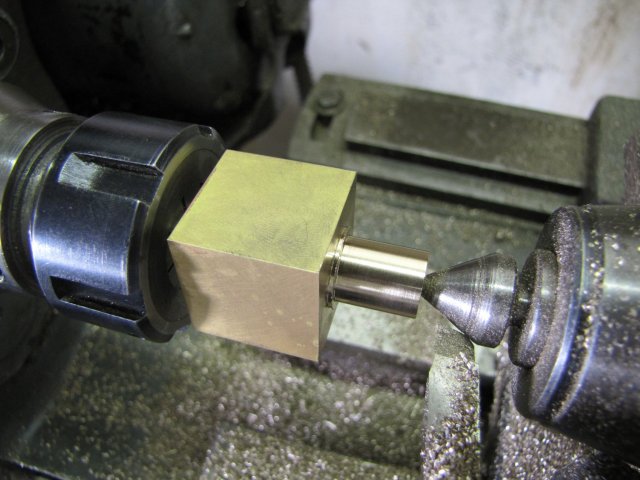
After a pickle in citric acid for the part while I had a bite to eat (~ 30 minutes) I chucked up the 7mm end in the collet chuck on the lathe, and with the tailstock support in the previously-drilled center, I turned down the end to 12mm with a 14mm shoulder:
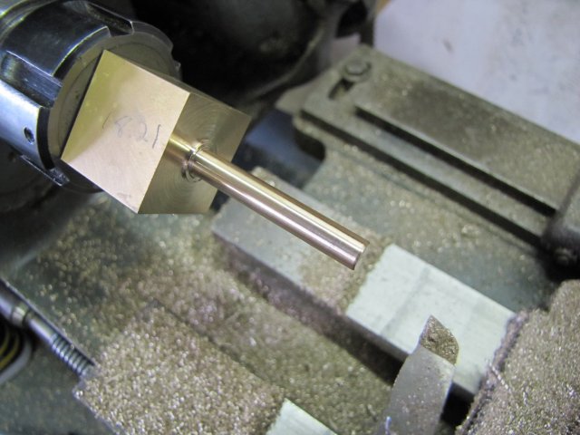
Flipped in the chuck, and clamping down on the 12mm bit, I VERY carefully turned down the 7mm round bit to 6mm. It has a fair bit of overhang, so a sharp HSS toolbit is the order of the day:
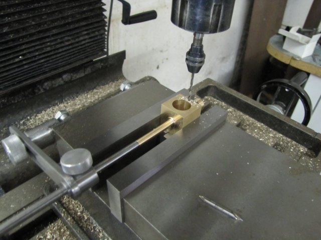
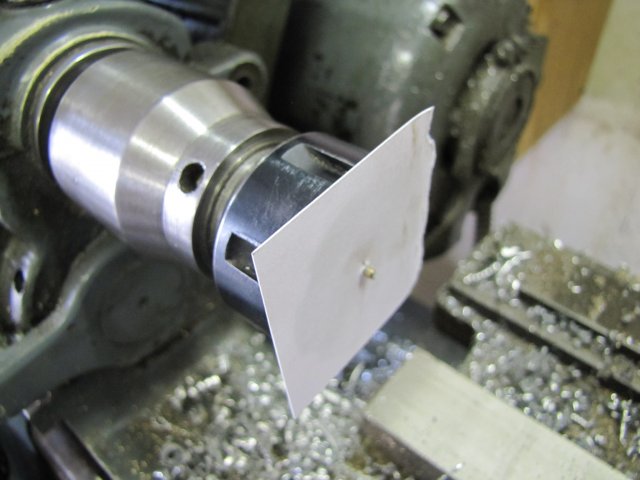
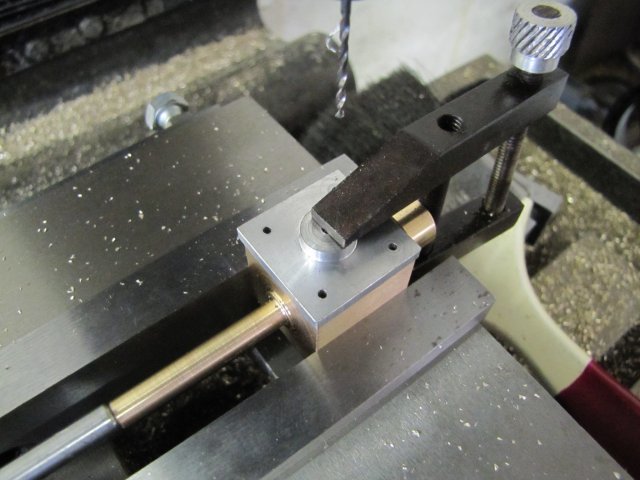
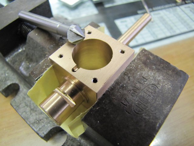
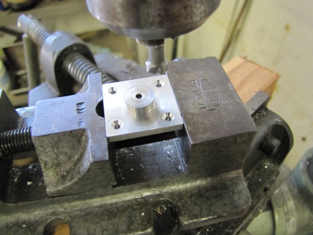
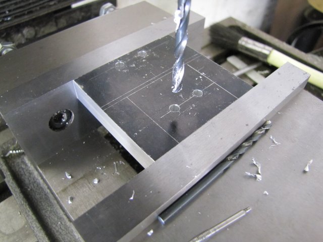
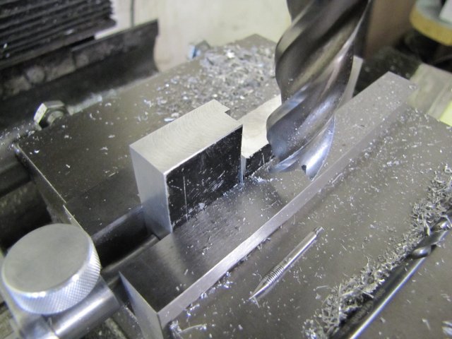
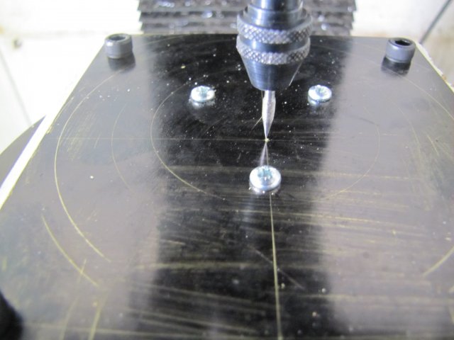
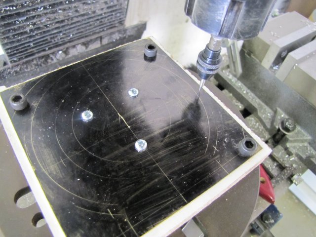
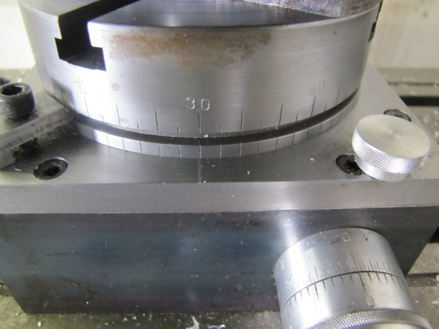
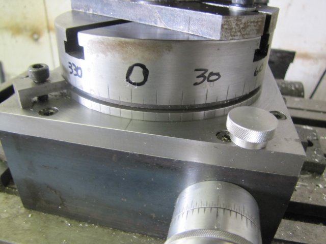
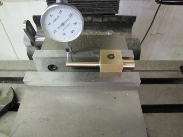
Then I set up that lot in the mill, using a dial test indicator (DTI) to check for squareness. Obviously, the mill needs to be in near-perfect tram for this and the following machining steps:
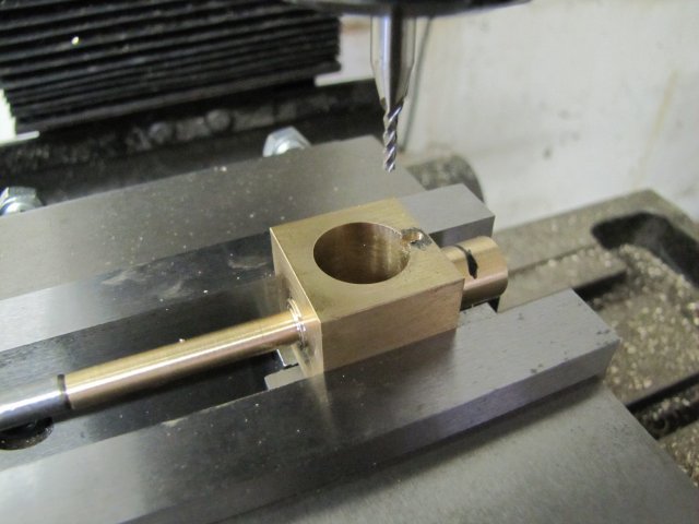
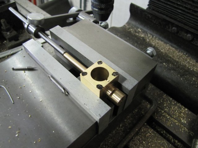
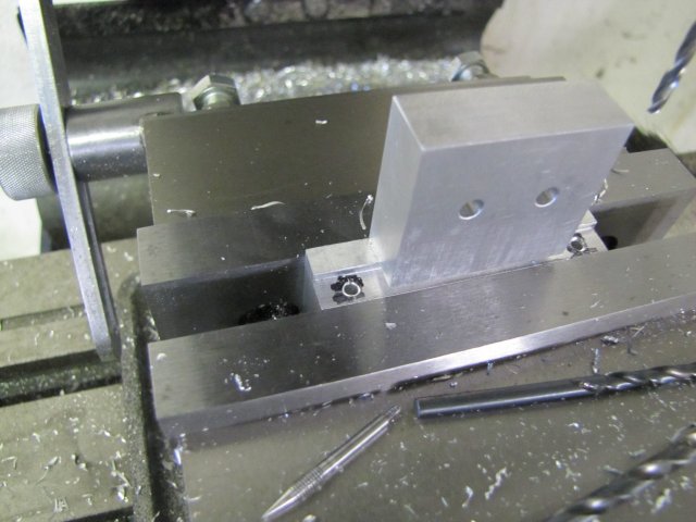
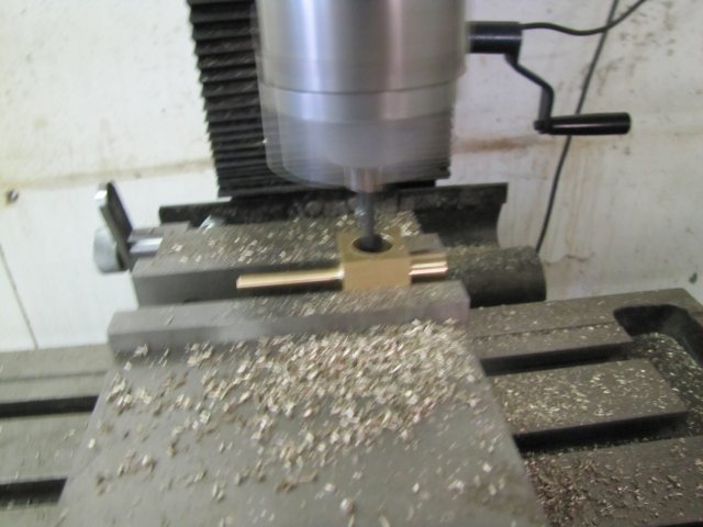
Then I drilled and bored out the cylinder with a couple of successive drill sizes -3mm, 7mm, 13mm and then the boring head to take it up to 16mm. A blurry action photo; as the boring head was running nicely balanced, this shot is at about 800 RPM, and very fuzzy as I was paying more attention to the feed than the camera :big::
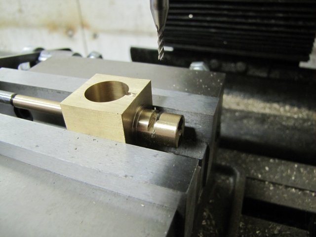
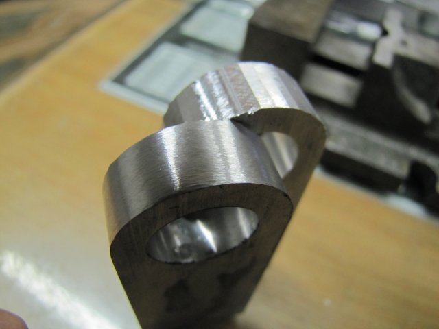
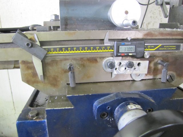
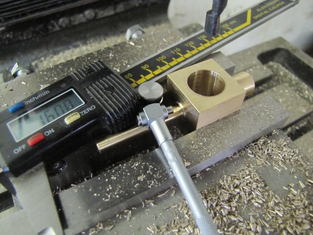
I checked for the final 16mm bore size with a telescoping gauge:
Well, not entirely true... :big: - the sizes measured are all OK, but I know that that digi caliper of mine is inclined to measure 0.05mm under size... - so that hole is actually 15.95mm :big:
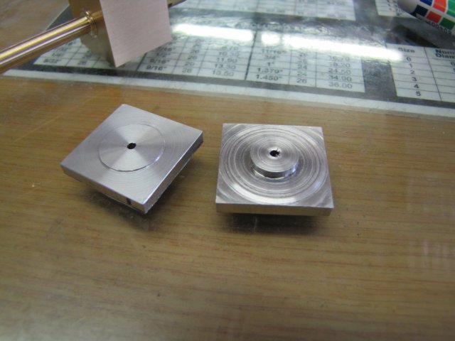
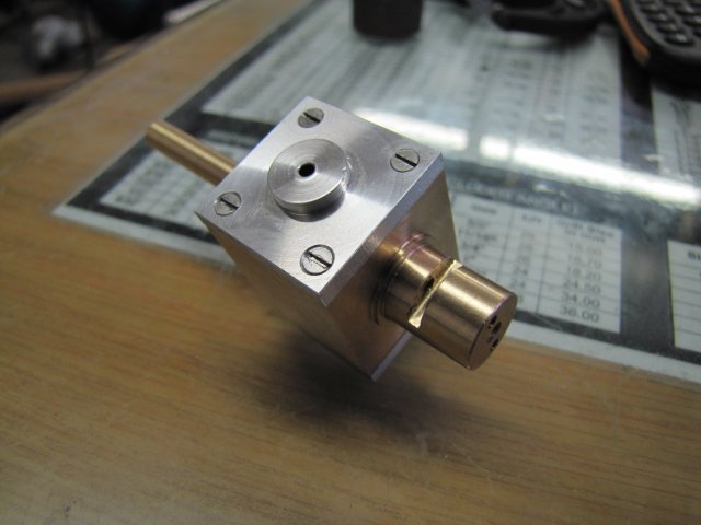
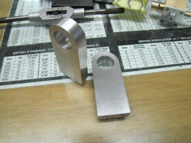
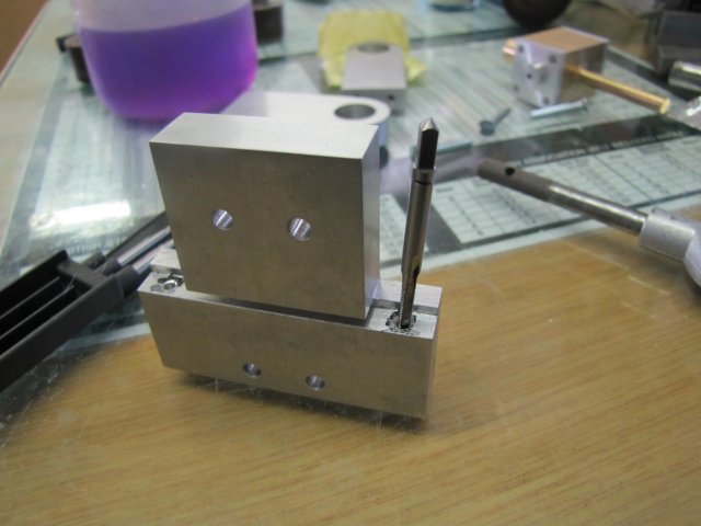
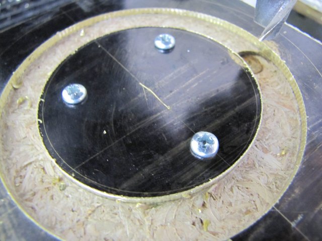
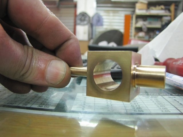
I ended up with this lot for today's work:
If you click on the last photo and have look down the left side of the non-perfect bore, you'll see the slight oval where the shaft joined the body; at least the silver solder job went exactly as planned
I wanted to be a bit further along today, but a neighbour popped in with a a gift and his young 'uns in tow. The gift is a very drinkable bottle of Scotch in return for fixing his wife's treadmill last weekend, and the young 'uns wanted to see some of my engines running. It's just as much fun as machining - if not more so - showing off my simple engines to a four and six year old... They seem to like the Elbow engine , the Comber, and of course the half-finished Cracker... pft pft pft ;D
Kind regards, Arnold