A Small Vertical Steam Engine

Home Model Engine Machinist Forum

Help Support Home Model Engine Machinist Forum:

This site may earn a commission from merchant affiliate links, including eBay, Amazon, and others.
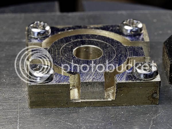
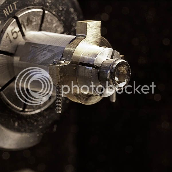
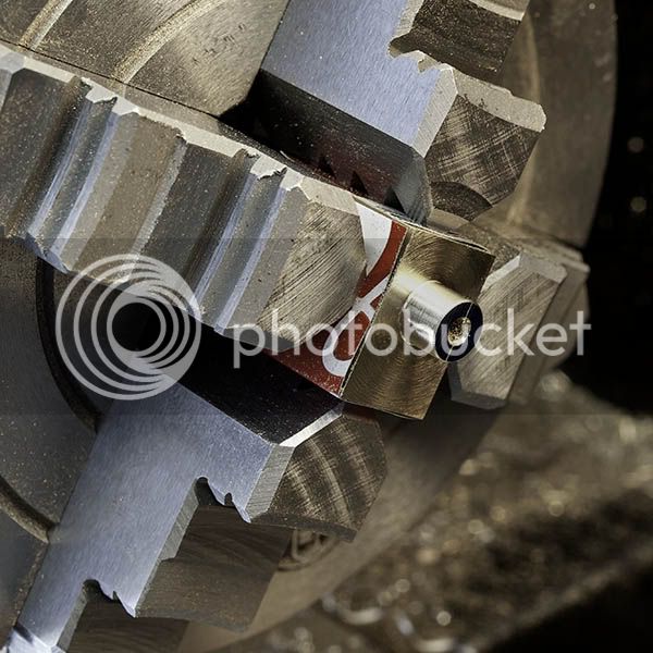
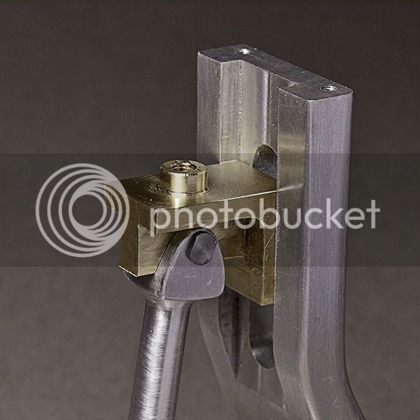
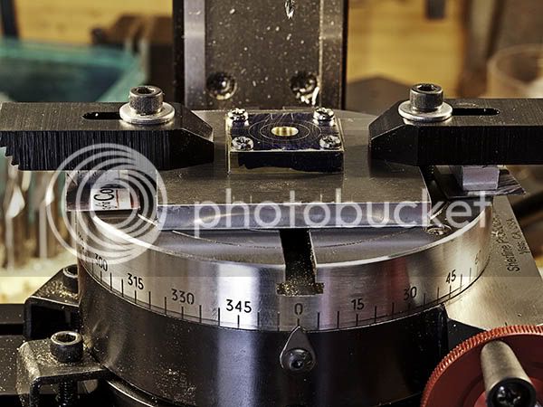
Making nuts was driving me, well, nuts so I quit and started on the eccentric strap. The bearing is machined with the two halves soldered together as usual. The join is central to make it easy to find the centre for drilling and reaming the reference hole. I decided to mount the part to a plate to avoid stressing the soldered joint (my last one fell apart:wall:) and to make it easier to mount in the four jaw chuck later. First pic is of the setup ready to go.

EccentricStrapSetup.jpg


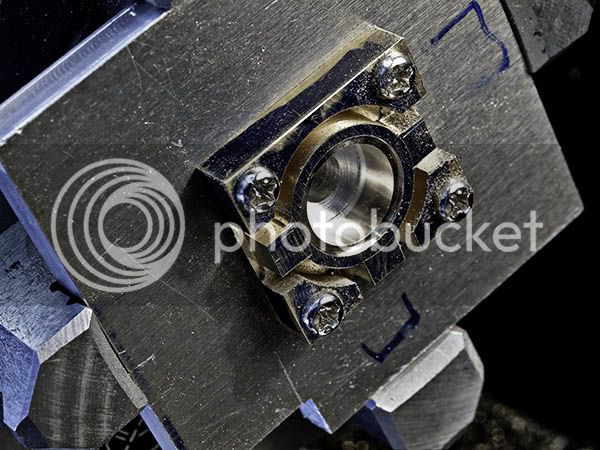
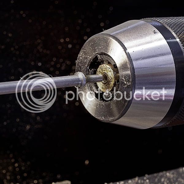
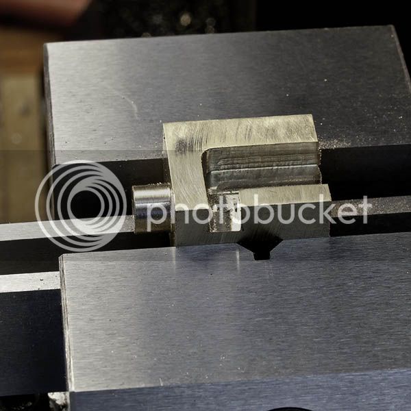
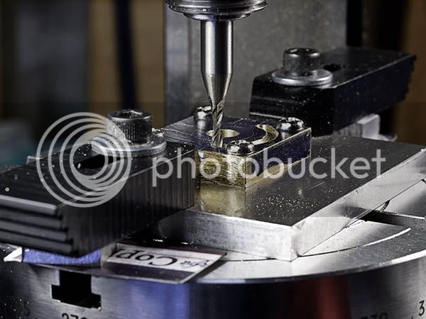
The strap is quite small and needed small corner radii and hence a 2mm diameter cutter. This makes for slow work and the constant fear of the cutter breaking. The depth of cut was .005" so at least the feed was quick.

EccentricFirstCut.jpg


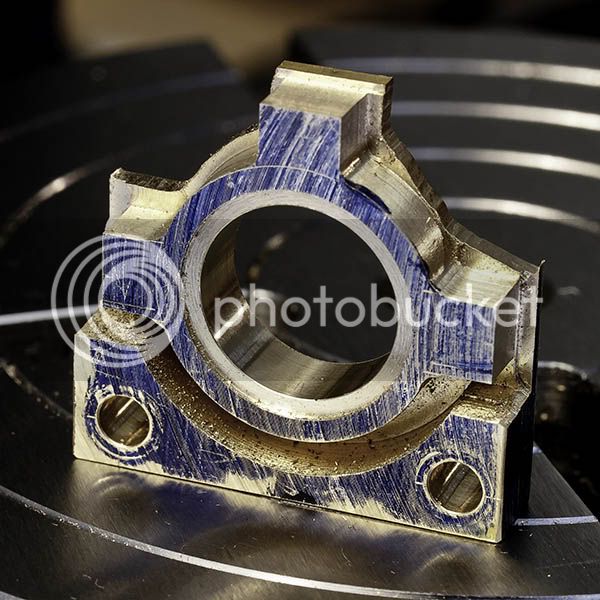
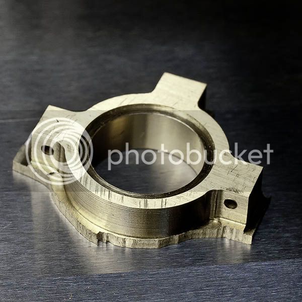
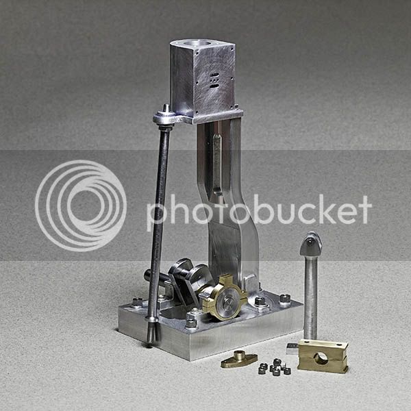
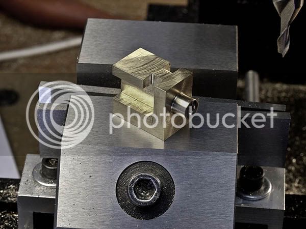
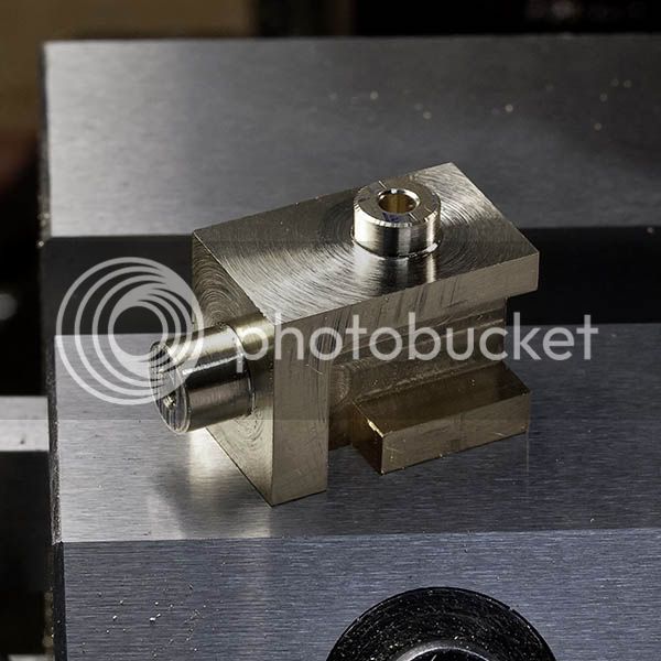
Last shot shows the progress so far, the milling nearly done then off to the lathe to size the bore. The little piece of brass shim is a very short homemade ruler so I could measure how deep the cut had gone without winding the cut off at all.

EccentricStrapProgress.jpg


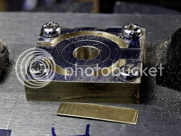
More tomorrow with a bit of luck:)
 
  • Like
Reactions: gus
Thanks for showing machining of eccentric strap using Rotary Table. My next strap will machined likewise. Take care with last cut.

Looks like my DIY Rotary Table will be very useful. e.g. Used it today to markout the 40 degrees offset intake on the IC engine shaft.

Good Luck
 
Gus, the strap is not cut all the way through, there is a liitle over 0.5mm left to hold it all together. I intend to mount the aluminium plate with the strap to the 4 jaw on the lathe. All will be revealed:)
 
  • Like
Reactions: gus
Looking good Jan. It is the simple things like the make-shift depth gauge that make me go, "Why didn't I think of that?"

I'm looking forward to seeing this engine all complete :)
 
  • Like
Reactions: gus
Got a bit left to do yet Brian but we keep chipping away at it:)

Carried on with the eccentric strap today, first shot is the milling complete.

EccentricStrapFinishMill.jpg


It was off to the lathe then to bore the 12mm for the eccentric. I was much happier tightening the 4 jaw onto the ali plate rather than the brass, much less potential for destruction!

EccentricStrapBoring.jpg


With the bore done some of the waste was sawn off with a jewelers saw ready to drill for the fasteners. The rest of the waste was left on as it provided a reference surface to set the work on.

EccReadyfordrilling.jpg


The holes where drilled and the rest of the wast sawn off. The remains will be mounted on an expanding mandrel so the the strap can be turned to width. But that is a job for tomorrow.

EccentricStrapCutout.jpg


The machining is less than perfect, the curves and straight lines don't blend too well. At least there is material to remove rather than an undercut to get rid of. The excess will be taken care of by a couple of strokes of a file.
 
  • Like
Reactions: gus
After nine straight days in the workshop I feel about as relaxed as I ever get, retirement looks very attractive right now:)

Picked up where I left off yesterday, making the mandrel to turn the eccentric strap and finish turning the strap to width. Tooling is not as time consuming to make as it looks and most often produces a better job. The strap is still soldered together and the screws where added for a bit of extra security, didn't want the mandrel to split the joint.

EccentricStrapTurn.jpg


The rod for the strap is going to get redesigned so that is finished for now.

With a couple of hours left to play the stay rod was calling. The rod is 108mm long but 4mm diameter with a shoulder at either end. Little spindles like this tend to be a bit whippy but there is no way to use a steady. To stiffen the setup one end of the rod is gripped in the collet chuck while the other end runs in a bush held in the drill chuck. With a sharp tool and light cuts this worked out well enough.

StayBar.jpg


Just for fun I put all the completed parts together to see how things where coming along.

SeptGA.jpg


Back to work tomorrow, that will slow things down:(
 
You made great use of your time off Jan! The engine is really taking shape :)
 
That was some real nice bit of work Jan. Your engine is looking great and love your detail photos. That is going to be a beautiful looking engine.

Don
 
Thanks for dropping by everybody and glad my work is of interest. For my part, I am enjoying myself a lot. Now if I could only get more time off work...

Gus the plans are being drawn up as I go. The design is a mix of various designs with a fair bit of added detail. It gets more complicated every time I look at the drawings and at that rate will never be finished:) The idea behind building this particular engine was to learn how to make engines look a bit more realistic, I prefer the appearance of a scale model but it adds a huge amount of work. Work on drawing for the next model has started but I wonder if I will have the courage to attempt making it.
 
Several bits of material arrived during the week so I had a choice of what to make. The cross head got the vote, I was given a bar end of 2" brass to do the job with. Here is the model view of the part so that the process makes a little more sense.

CrossheadInv.jpg


The sequence of operations was planned in advance given that the part has an awkward geometry. First operation was to turn the sliding face and drill and tap for the retaining screw.

CHSlidingFace.jpg


Next op. was to mill pockets for where the con rod will eventualy go. Material was left at the bottom so that the part could be clamped easily in further operations.

CHMillPocket.jpg


And now the part with both pockets done.

CHSecondPocket.jpg


The hole for the piston rod was drilled in the mill to guarantee placement accuracy and squareness, then off to the lathe to turn the boss. Note the nut used to protect the boss on the sliding face.

CHTopFace.jpg


And that is the part so far, still needs the excess milled away and the hole for the con rod pin. No doubt it will get a bit of filing and sanding later. Hopefuly finish up tomorrow:)

CHProgress.jpg
 
I always enjoy seeing each installment of your progress. As other people have mentioned your photos (unlike mine) are top notch. Keep it up.

Vince
 
Thanks Vince, I do enjoy my photography. I use a DSLR with a macro lens all mounted on a tripod. The pictures are edited in PhotoShop and that makes a big difference. All in all it is time consuming but, if a few people like the pics, worth the effort.

I finished the crosshead today after having the day off yesterday. The majority of the waste was sawn away and then the remainder cleaned up in the mill. Still lots of filing and fitting to do but that will come later.

Crossheadfin.jpg


I have to pause again now to make some tooling. This time I want to finish making a set of die holders so that my stud making process actually works:confused:
 
Very impressive Jan. I got a pretty good stud making procedure going on my PMR1. The best part was an idea I gleaned from here. Use an emergency collet tapped to your stud threads to hold onto the finished end when you tap the second. I found that the collet worked much better than the threaded holder I made first.
 
That is some very impressive bit of machining Jan, love following your progress. I am getting anxious to see it run now. Thanks again for your excellent photos.

Don
 
I too must add my thanks for you efforts on the photography. Your pictures really help to see and understand your parts and processes. Beautiful work on the machining as well. :)

Todd
 
Brian the collet idea is a good one. For my setup I would need to make my own, probably a tapped slottted cylinder to go into my ER32 collet chuck. So far I have cheated a bit, the short studs are threaded for the whole length while the long ones can be gripped in the ER32:)

I too look forward to the engine running Don but suspect that is a way off yet!

Glad you are enjoying the pics Todd, I will keep it up.

Of all the machining processes, the making of nuts and studs has caused me the most trouble. The notion that these common parts should somehow be easy to make has got in the way of taking them seriously enough. No doubt the small scale contributes to the difficulty, M3 and above are straightforward but the smaller sizes are very unforgiving. My previous effort at threading studs used a standard die holder kept square by the tailstock, not a great method. I decided to make a set of die holders to a design by George Thomas, the design is from his book The Model Engineers Workshop Manual. If I had to keep only one of my books it would be this one. The methods explained seem overly complicated at first glance but they just plain work! Here is a pic of the holder assembly so the description makes sense.

DieHolder.jpg


Please excuse the screws sticking out everywhere, I forgot to order the grub screws:wall: The section that holds the die is seperate so that each die has its own holder. The huge benefit of that is that you only adjust the die to cut size once rather that repeatedly as with a standard holder. It's a fair amount of work to make all the bits but well worth it. Threading is now quite easy and quick. So far I only have two holders to cover the two most common sizes but I will make more.

Not much to show for a weekends work but hopefully get a bit more done next week.
 
Nicely done Jan. Which part of the die holder rotates? Does the larger cylinder rotate on the pin in the chuck?

Todd
 
Thanks Todd, the large body does indded rotate on the 3/8" diameter pin. The spigot on the front of the large cylider has a flat on it to take the grub screw from the die holder. The short die holders are quicker to make and save material realtive to making the holder in one piece. Each time I make a piece of tooling I feel more comfortable in my shop:)
 
Back
Top