A Small Vertical Steam Engine

Home Model Engine Machinist Forum

Help Support Home Model Engine Machinist Forum:

This site may earn a commission from merchant affiliate links, including eBay, Amazon, and others.
Long way to go yet Vince but some significant parts completed.

Fred, if you go to the first page of the build there is a 3D model of the engine, which is done in Inventor, but I also have a full set of drawings to work from.

Jan
 
Next job on the list is the crankshaft. I bought some silver solder for the assembly but might end up gluing and pinning it instead:D 
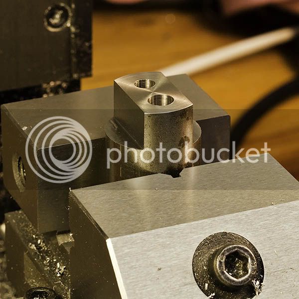
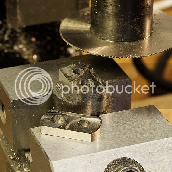
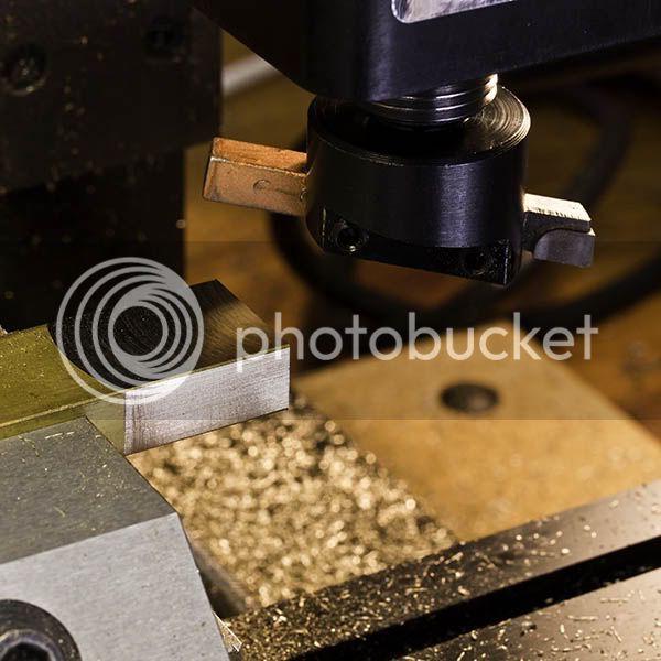
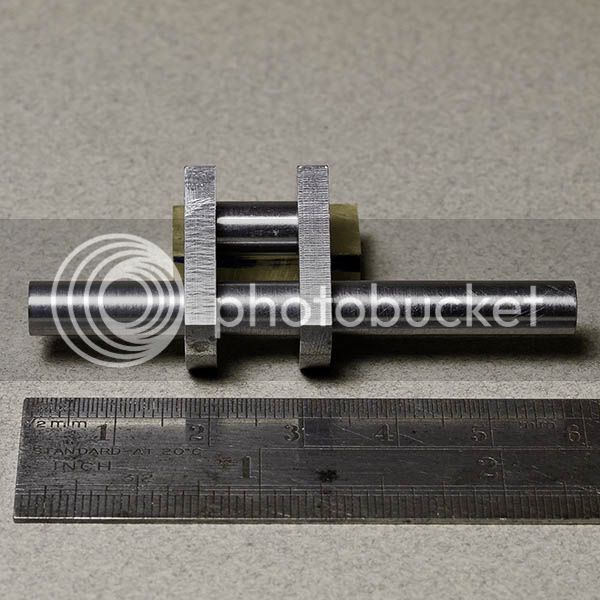
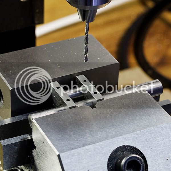
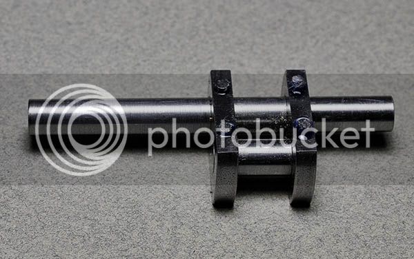
The crank cheek ends are radiused to 12mm but the leaded steel I had was 22.2mm dia so I just changed the drawing. The bar end was faced in the lathe before milling two flats and drilling the holes.

CrankCheekMillDrill.jpg


The cheeks where then sawn off with a slitting saw. It's the first time I have "parted" with the saw and am impressed with how easily it went. Due to my poor technique the sawn faces where a bit rough so they got a quick flycut.

CrankCheekSaw.jpg


While I was in the mood for milling I started on the main bearing. The nearest size piece of brass I have is well oversize so the first operation was to mill the end square, the sides parallel and the top face just cleaned up. Those four faces are as accurately square as the machine will allow.

BearingSquare.jpg


The bearing was then seperated from the bar and slit in two with the slitting saw. I would like to solder the two bearing halves together for machining but have no source of heat yet so it will have to wait. Back to the crank tomorrow.

Jan
 
Looking good Jan, I always get the jitters ever time I silver solder, even thought the work comes out OK. Do you ever get over this fear? Your crank approach is interesting.

Don
 
Hello,

Really beautiful work, CNC users would go faster for sure, but would not a more beautiful finish their parts, you're a passionate work well done, as many here!
I am your Trhead until the end.
Any plans for micro-biller with the glass ball, it will help hang out the primer before the final coat, it's just an idea, because I have these problems due of not having done this, perhaps be you another idea.
Again congratulations ;)

cordially
J-M​
 
Just one more picture from the weekends work, the cranshaft bits put together. The parts are still in need of a good polish.

CrankParts.jpg


Don, the idea behind using the round stock was twofold, I had a piece and I wanted to avoid rounding the ends of the cheeks them being quite short. It's a few years since I did any silver soldering but, with the crank, it's mainly not wanting to oxidise my bearing surfaces and then having to polish them up again. With such a small engine the glue and pins are unlikely to fail I hope;)

luck_luke, thanks for your comments, I do indeed love my machining and the subject itself. I call my time in the workshop "perfect peace" where the rest of the world fades away. The paint system still needs some research but bead blast, etch prime and then paint seems to be the favoured method.
 
Very nice work Jan. Thanks for posting your setup photos as well as photos of your parts. I always learn a lot from setup photos.

Your crank should work very well in your steam engine. I have a built-up crank in a 1/4 scale Galloway hit and miss engine which is much more severe duty than your engine will be. The crank is held together with Loctite 609 and tapered pins.

Regards,

Chuck
 
Hi Jan looking forward to see how your crank shaft goes.

Don
 
Chuck, thanks for your comment and confirmation that a pinned crank works out OK. I guess if pins work on an IC motor a tiny steam engine will be no problem.

Don, the crank should get done this weekend and hopefuly a bit more also.

As for completion WhisperFan, that is some way off in the distance but the next engine is in the planning so I need to move on;)
 
Just one more picture from the weekends work, the cranshaft bits put together. The parts are still in need of a good polish.

CrankParts.jpg


Don, the idea behind using the round stock was twofold, I had a piece and I wanted to avoid rounding the ends of the cheeks them being quite short. It's a few years since I did any silver soldering but, with the crank, it's mainly not wanting to oxidise my bearing surfaces and then having to polish them up again. With such a small engine the glue and pins are unlikely to fail I hope;)

luck_luke, thanks for your comments, I do indeed love my machining and the subject itself. I call my time in the workshop "perfect peace" where the rest of the world fades away. The paint system still needs some research but bead blast, etch prime and then paint seems to be the favoured method.
_________________

Hello Jan,

You'll make it work steam, I do not think you have given yourself as much harm to get it working compressed air, coupled to a varies Propeller pitch, you might find way to slow that it does not stall, and with a regulator such as the website, put the steam, and through propeller starting forwards or backward and for phasing out the propeller in "flag", what do you think ? :)

Cordially
J-M​
 
Hi Jan,

I don't think you will have any trouble with the use of Loctite and pins for the manufacture of the crankshaft if you make the tolerances just enough to allow the Loctite to penetrate, which from the photograph you obviously have. The pins I would Loctite in as well, the reason being when I made a similar crankshaft although the pins were as I thought a tight fit, one came out of the journal due to the centrifugal forces when spinning it in it's bearings at high speed. I noticed it before it did any damage.

Brian
 
Hello Jan,

I thought about this on the crankshaft, and on each side of the axis of connecting rod in your place I should have done a small shoulder on the axis to eliminate the friction on each side pieces on the crankshaft,This is just an idea, but I think it is not bad.

cordially
J-M​
 
Thanks for the comments, it's good to get a little debate going!

luky_luke, my engine will run on compressed air as I have no boiler. I did look at making one but the materials required proved to be very expensive, so if I make one it will be much later. My engine is based on an industrial engine that was used for driving electrical generators so no propellors required;) Thrust faces are a good idea and I have included mine on the bearings, where it is easier to machine. My plan is to have a small gap on the crankshaft and allow the con rod to float a bit more so it aligns with the crosshead easily.

Brian, I will take your advice and glue the pins in. Having a pin work loose could cause a lot of damage to a mostly aluminium engine.

Jan
 
After polishing the crank cheeks I glued the parts together with Loctite and put the assembly asside to set. I forgot to mention previously that the crankpin has a step either end to ease alignment on assembly. Decided to use 1.5mm diameter pins so drilled appropriate holes half way through the cheek and pin.

CrankDrill.jpg


The pins where turned from 2mm welding wire and then glued into place.

CrankPinned.jpg


After letting the Loctite set it will be a matter of cutting the unwanted bit of crank and cleaning up the pins. The main bearings are next up for attention, I would like to get the crank rotating on its bearing mounted on the base.

I started on the big end bearing but forgot to take pics:wall: Anyway it wasn't a great sucess so I get to do some of it again anyway. I soldered the two halves of the bearing together but did a poor job using low melting point solder which was too weak. As a result when I reamed the bore the bearing split. Will now have to solder it together again!
 
Jan

That will be a fine looking crankshaft when you will finish it. Well done.

Vince
 
Jan i never made a crank bt pinning interesting approach. Looking good so far, you may consider a heavy grade soft solder like 60- 40 or 50-50 to get more strength.

Don
 
Jan, by the time you read this reply I am sure you have resoldered the bearing halves and completed the task of reaming, ready to move to the next task. However, I would like to give my experience with the use of soft solder. I use it many times during a model build, I find the bonding strength very good. The solder I use is a 60/40 multicore solder that comes in wire reels, the same type used for soldering components to printed circuit boards. The advantage of this type that it already has the flux incorporated in the solder and with small items such as the bearing halves use a soldering iron to tin both halves, prior to clamping them together and reflowing the solder with external heat such as a propane torch or hot oven. I use this solder to bond small items to mandrels that needs to be machined. When the item is too large to tin using my soldering iron, I use additional flux such as Bakers fluid with a propane torch but avoid placing the flame on the surfaces to be tinned by the use indirect heating. Sorry if I am teaching.....

Brian
 
Thanks for the comments folks, the crankshaft is now finished. I milled the excess off the pins and hacksawed the unwanted piece of shaft from the crank, followed by a lot of filing.

I did end up using 60/40 multicore to resolder the main and used some rosin flux I have in a pot. I didn't take any more pics of the bearing machining as it was not very pretty but the bearing works. I am not entirely happy with it and I may remake it later.

Brian, I am more than happy for people to add suggestions on how to do things, there is a lot of knowledge out there and saying something three times is better than not saying it at all:) I never though of using an iron to do the tinning, I just used a small butane torch and spread the solder with a flux soaked rag.

Just one picture, the crank, bearing and rod loosely placed together. The screws are just to hold it together and they will be replaced with studs and nuts.

CrankRodAssy.jpg
 
Didn't get a huge amount done on the engine this weekend, mostly filing and sanding the main bearing housings. They are now done and all of the parts glued together and the crank even rotates in the bearings!!!!

MainsFinished.jpg


The eccentric also got made along the way.

I need to make lots of nuts and studs, which I guess is an ever present task with engines. To make this a bit more efficient I have been making up tooling for the common sizes. Tooling is time consuming to make but will repay many times over in the future.

While looking at the sizes of the fasteners I started thinking about what scale this engine might be relative to a real engine, very back to front I know:D It turns out that the scale is about 1/8 so the original had a bore of 4 inches, quite a small engine. For this engine size the fasteners are scale also and are in the range M1.6 to M3.
 
Jan, that is looking good. Those bearing housings are fantastic! Keep up the good work.
 

Latest posts

Back
Top