a rather unspectacular stirling engine...

Home Model Engine Machinist Forum

Help Support Home Model Engine Machinist Forum:

This site may earn a commission from merchant affiliate links, including eBay, Amazon, and others.
Hi there,
hmm- is there something wrong with the posts? Too many pictures? Too much bullsh*tting?, Too boring? Looks a bit like monologise around here...
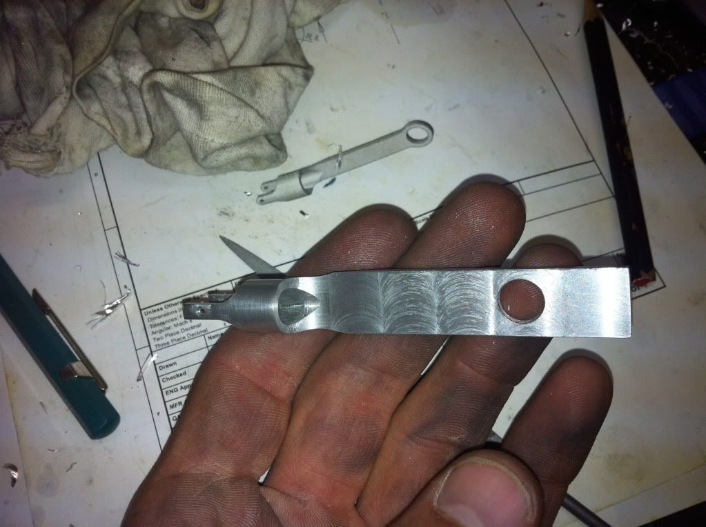
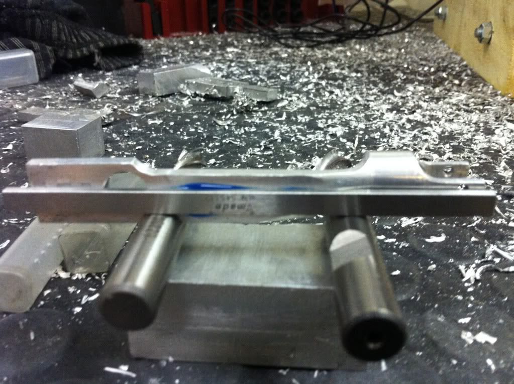
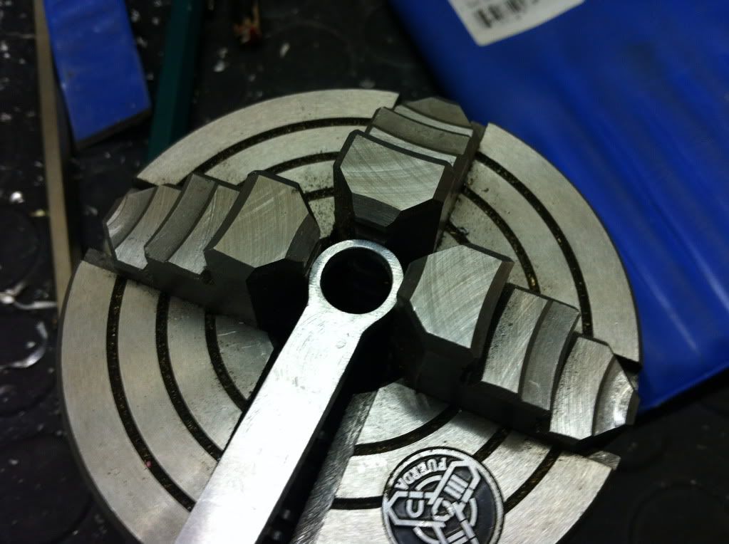
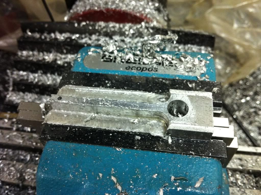
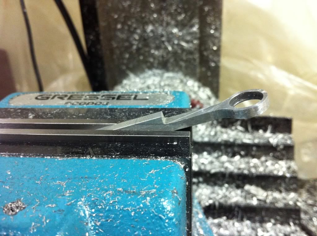
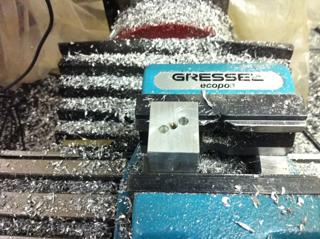
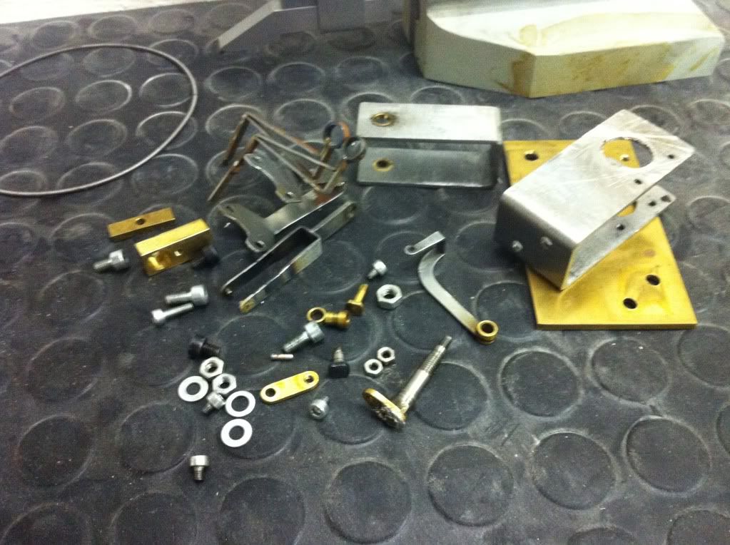
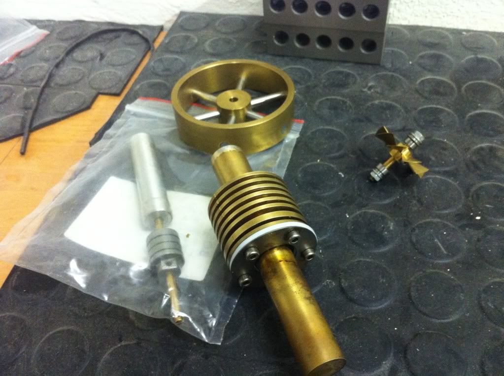
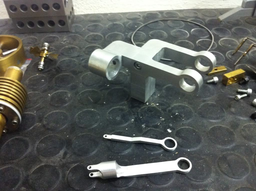
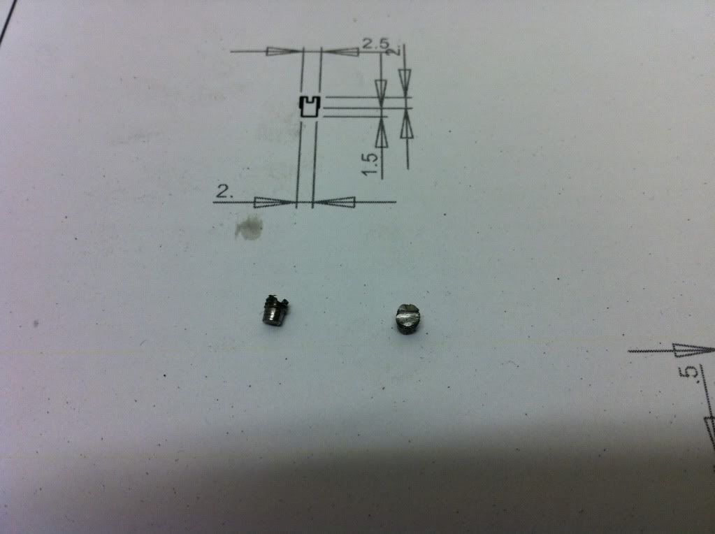
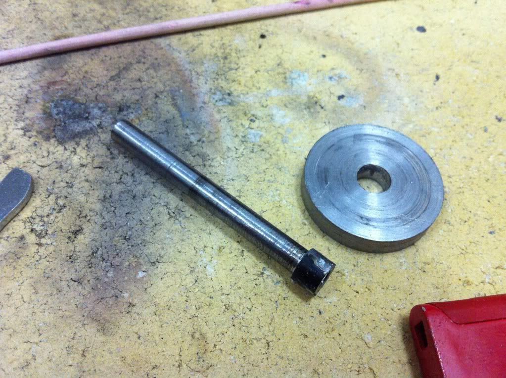
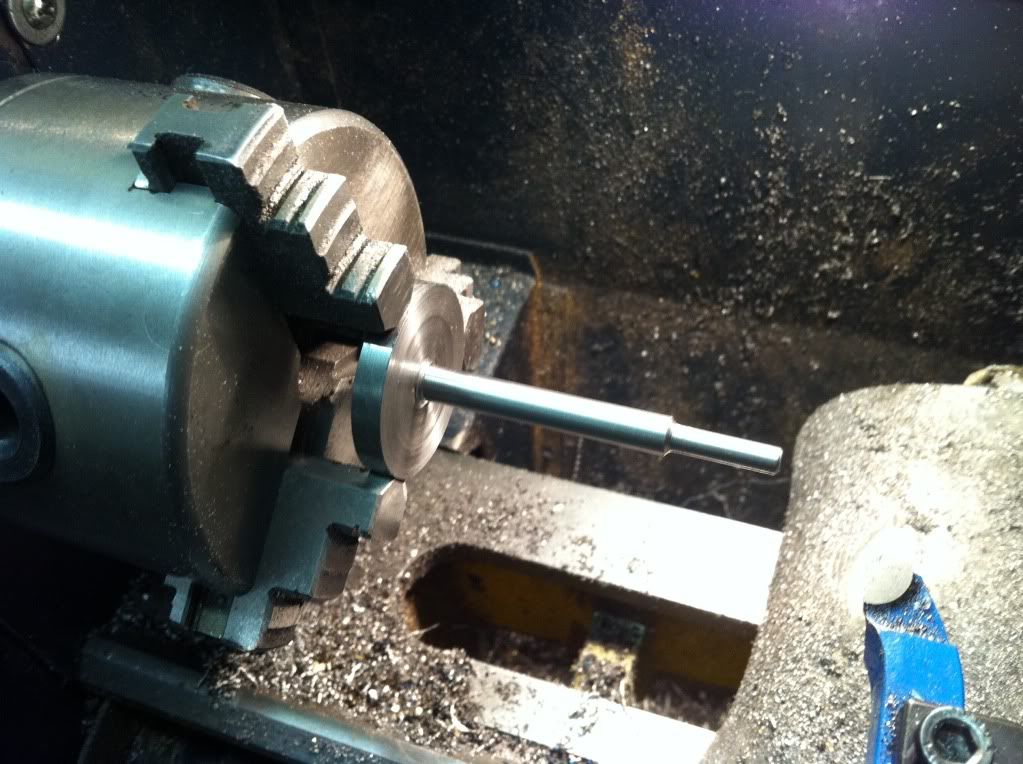
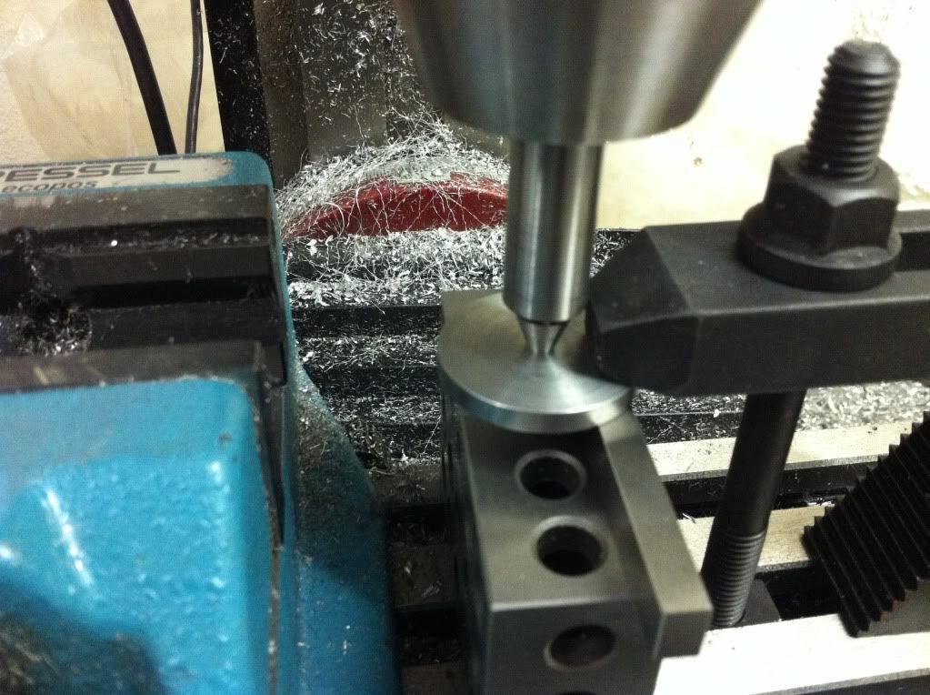
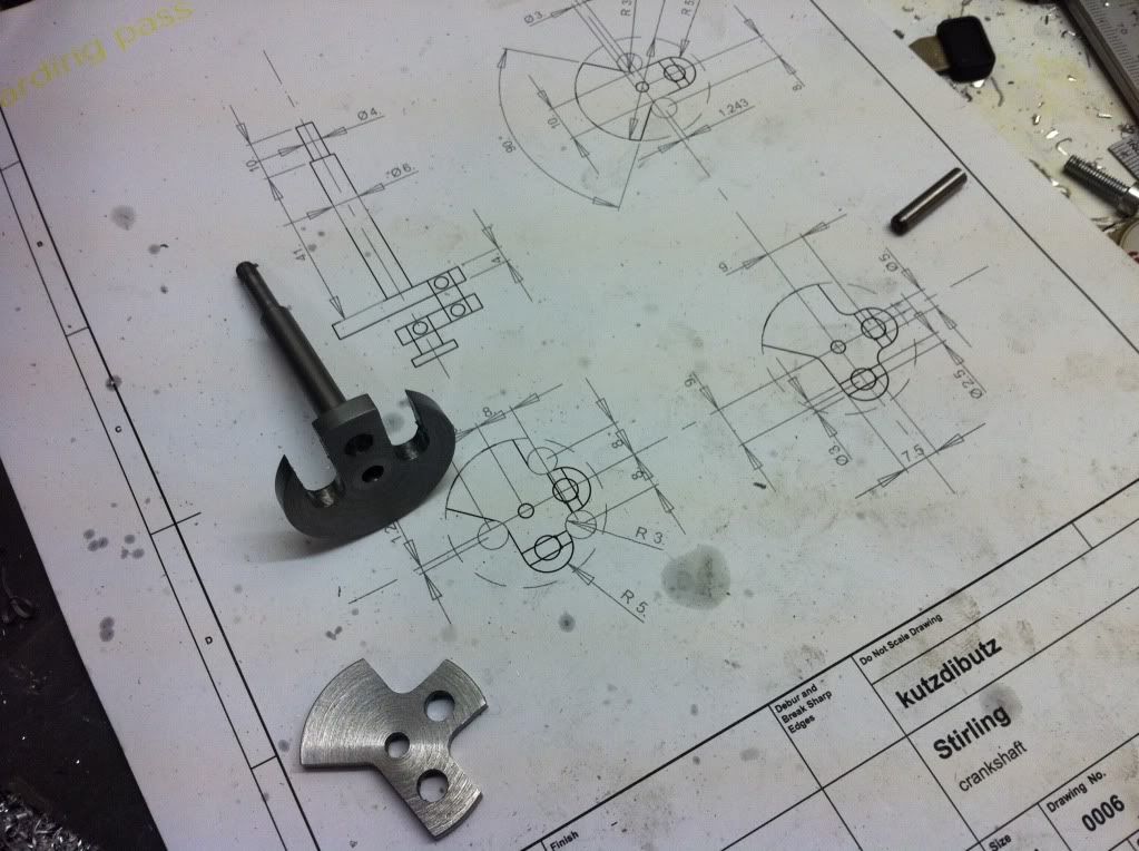
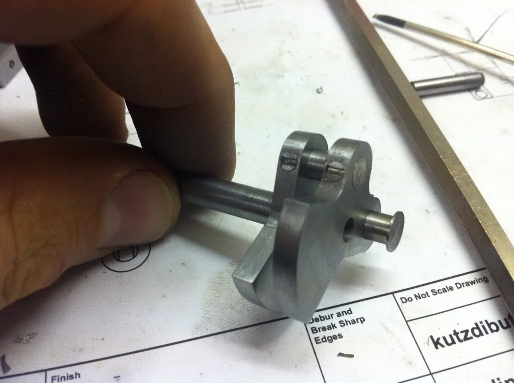
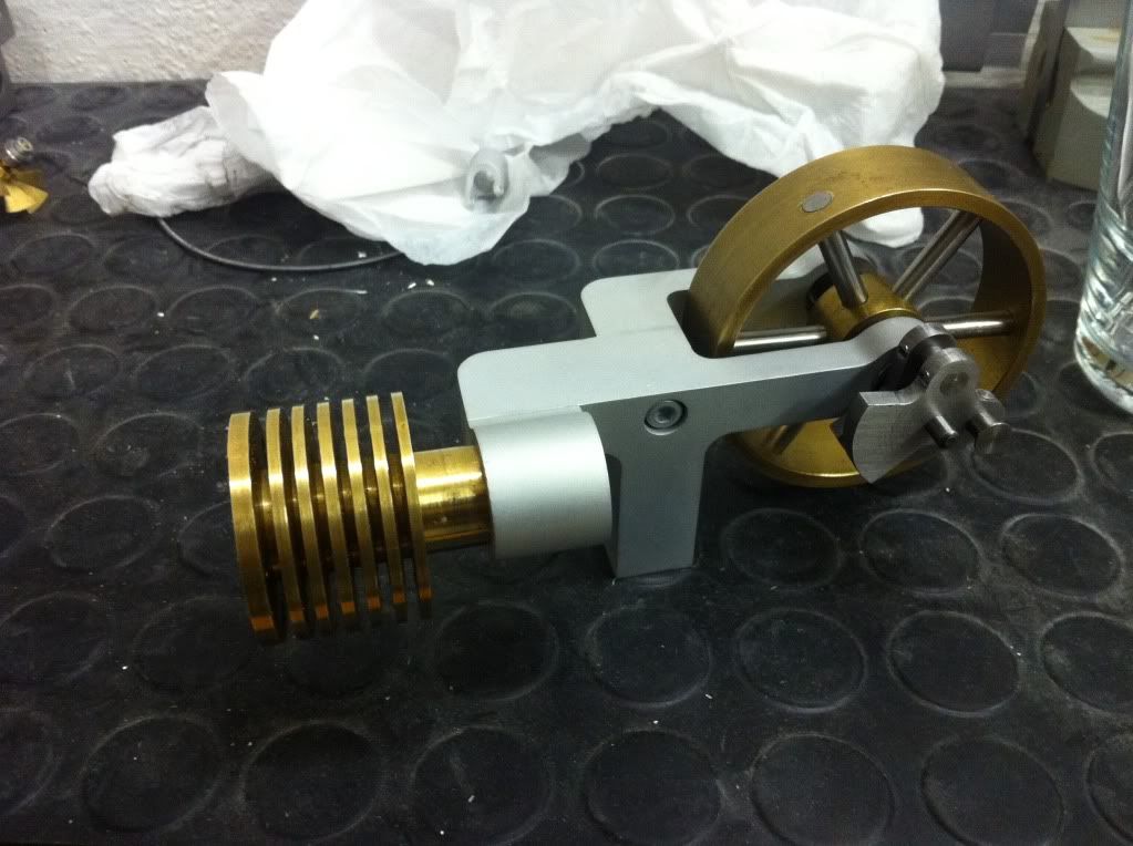
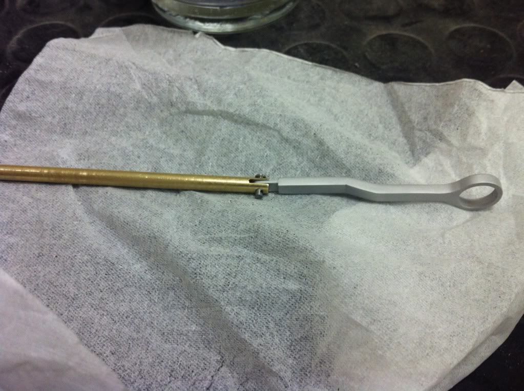
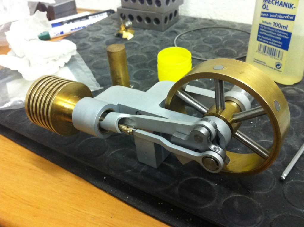
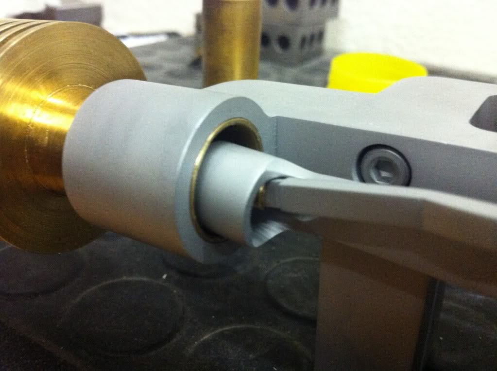
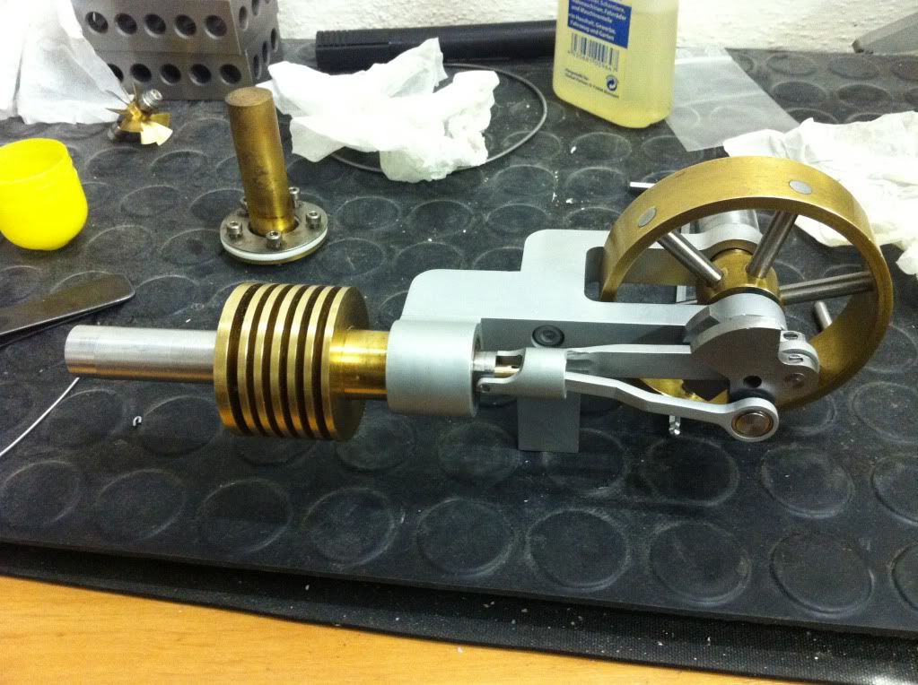
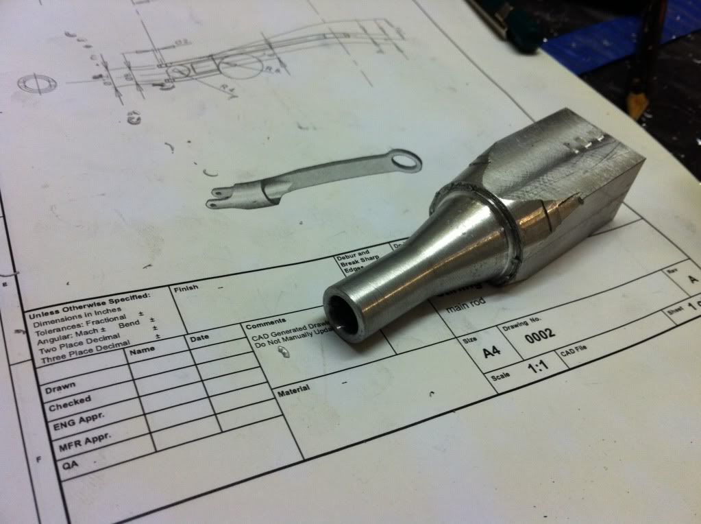
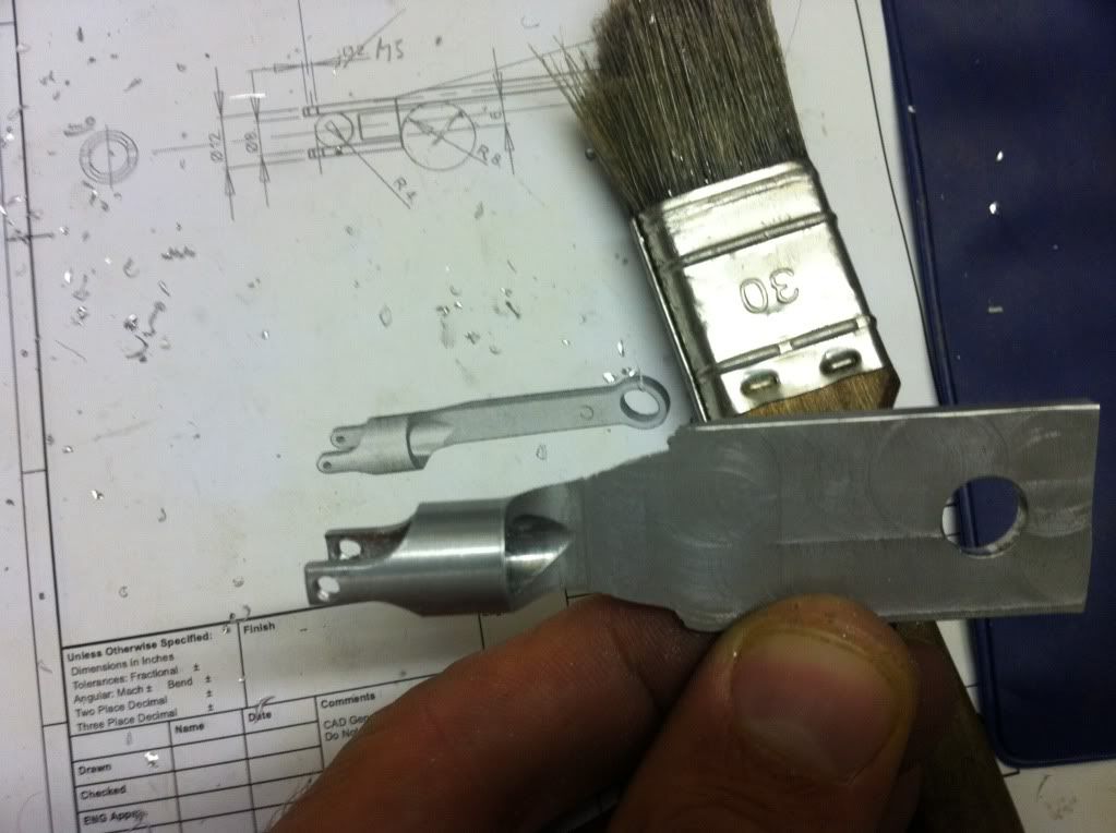
Anyways- I made it to the shop again and started the next part. This one will connect the power piston with the crankshaft. (eventually) Sketching it in CAD was sooo easy and quickly done- but making it for real took me some headscratching. First I cleared a piece of aluminum (of the same mavellous smearing sh*t) and placed in the 4-jaw. Center drill and turned the front bit round.

IMG_1076_zps67436717.jpg


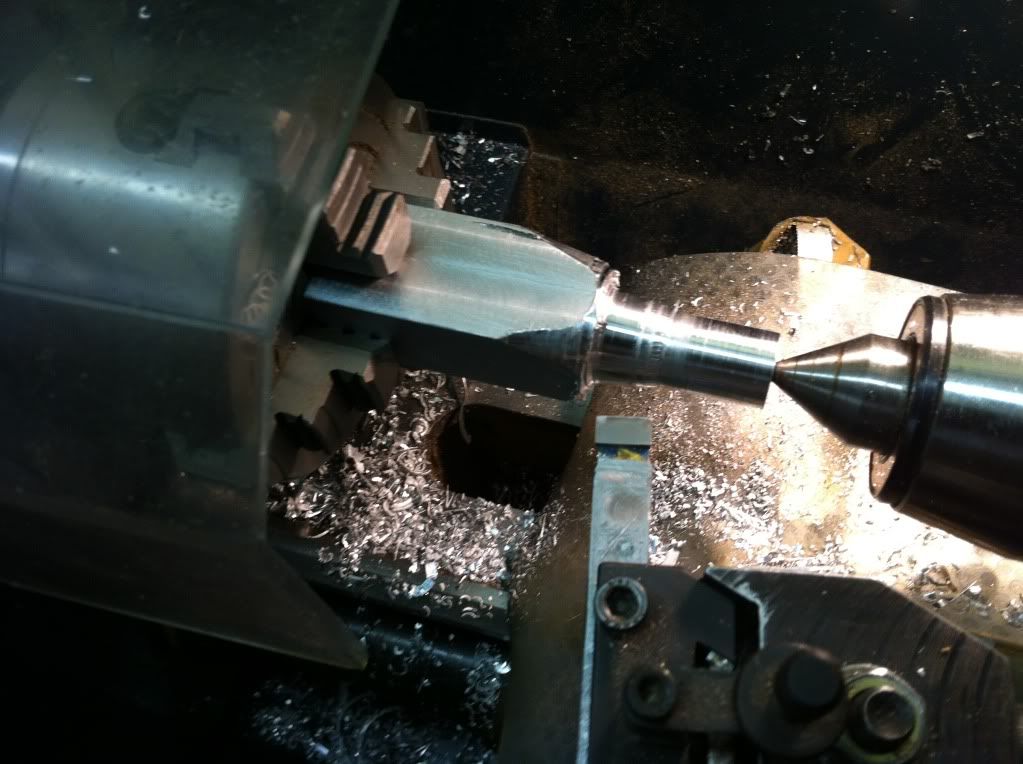
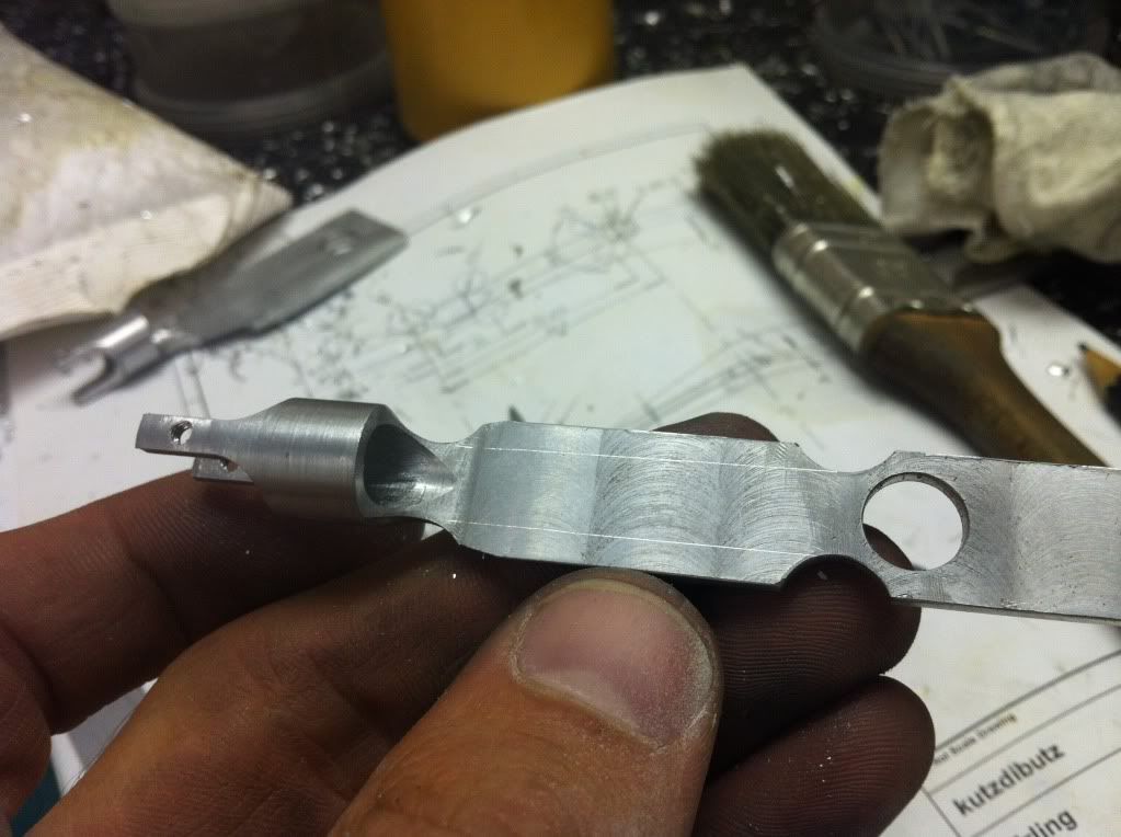
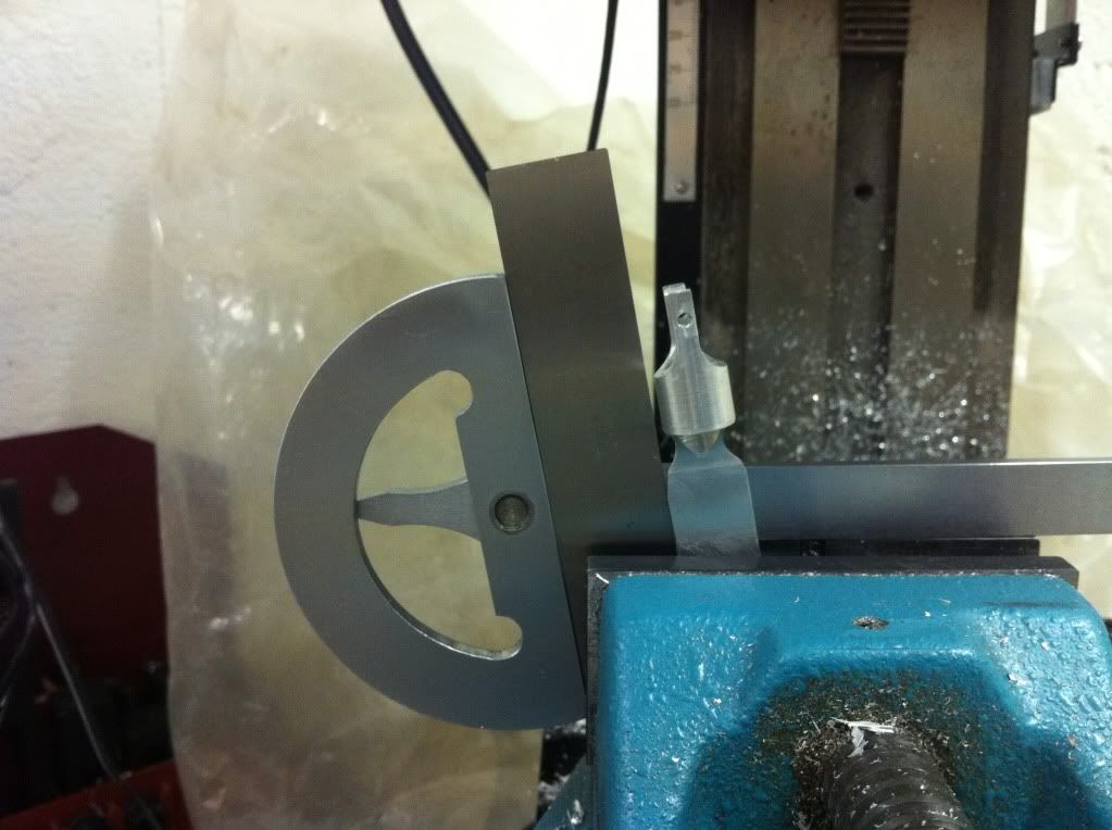
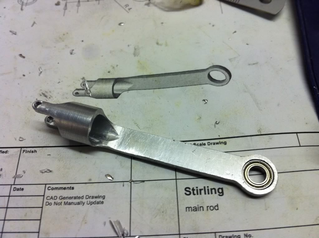
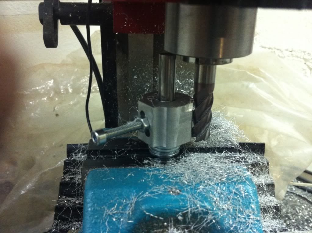
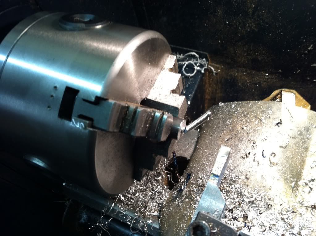
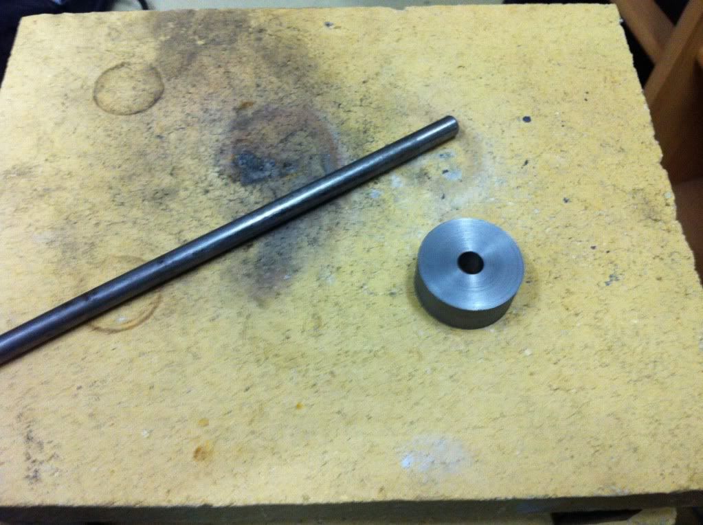
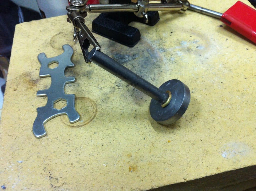
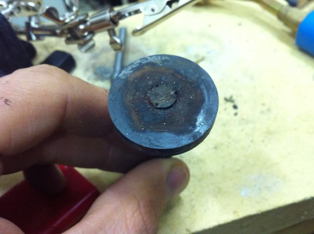
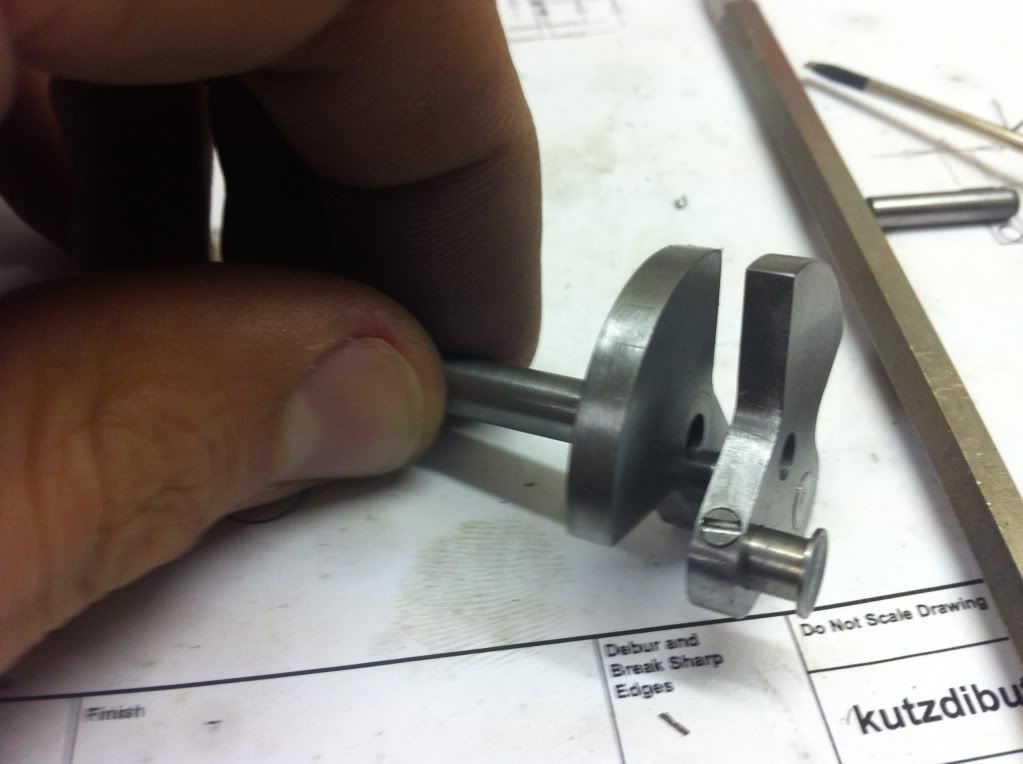
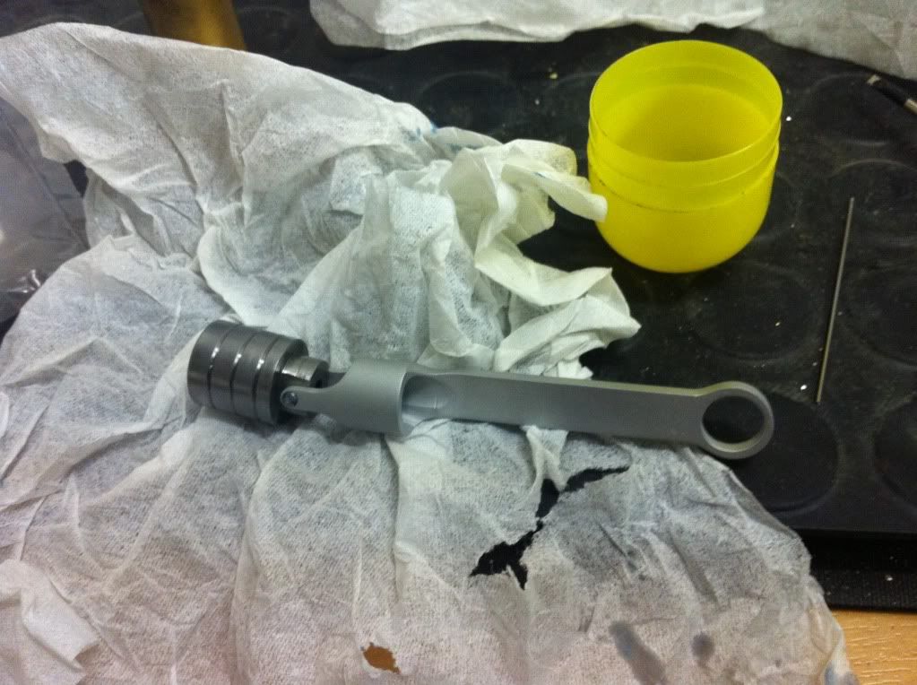
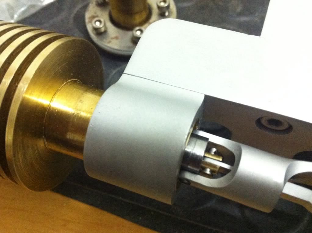
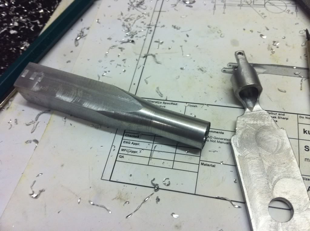
For the ange of the cone I 'adjusted' the cutter- and of course it did chatter like hell when it was cutting on the long edge of the tool. I also know I should have used the cross slide adjusted to the cone angle- but I was too lazy to take the support apart for back and forth adjustment and dismount all the chip protection I installed for my DRO only to do a proper setup for making the cone... At the end I removed the chatter-marks with a file. Not very elegant- but it worked... :hDe:

IMG_1077_zps6797311f.jpg


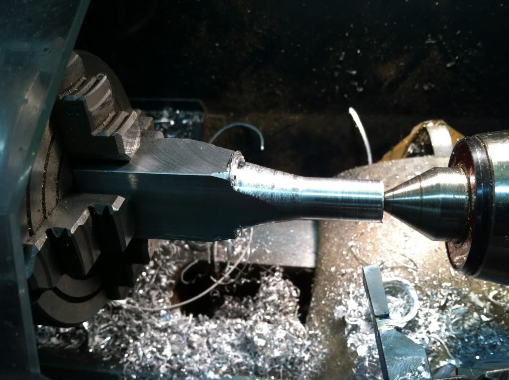
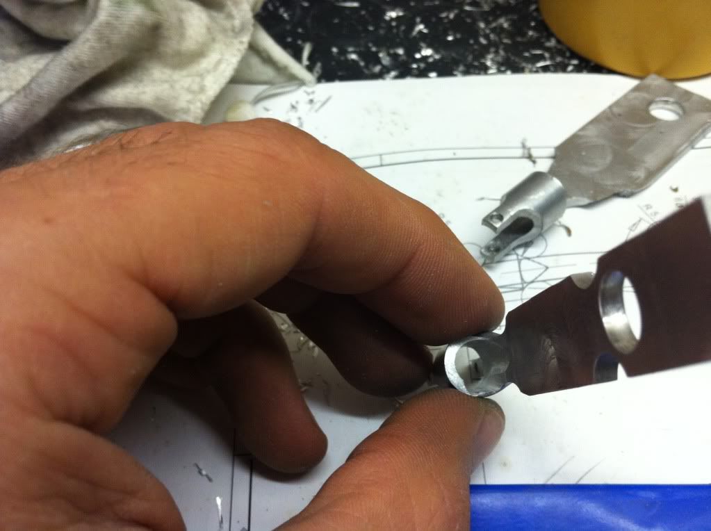
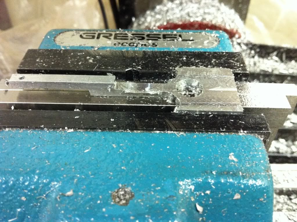
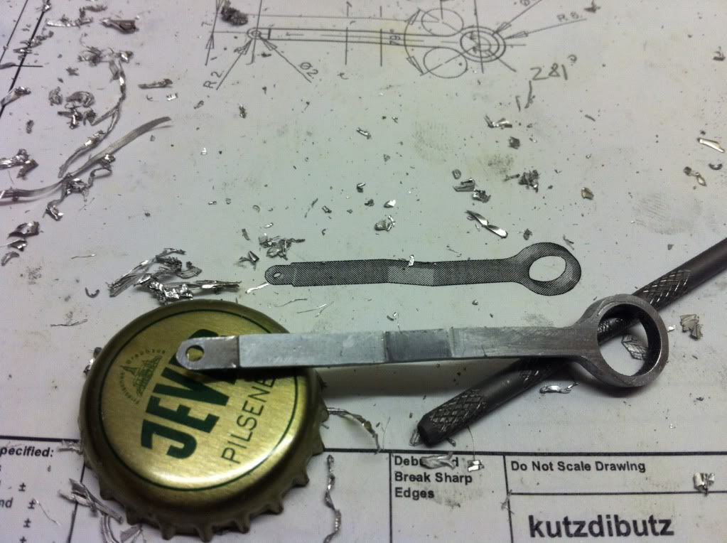
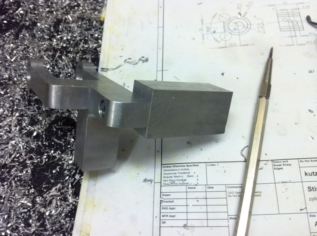
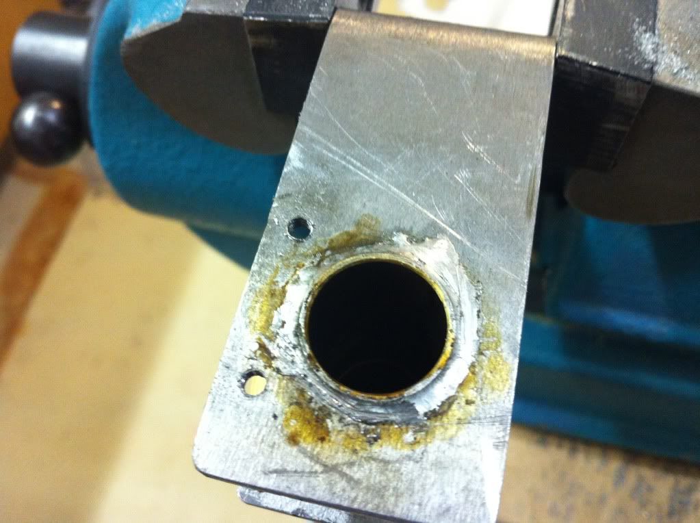
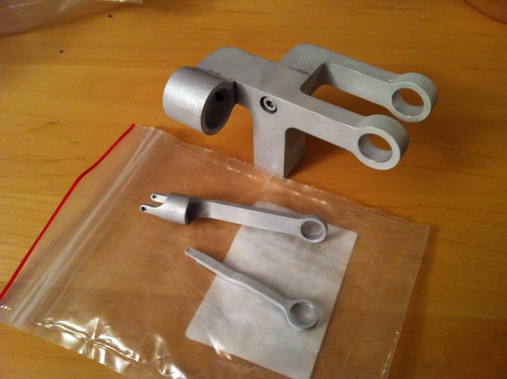
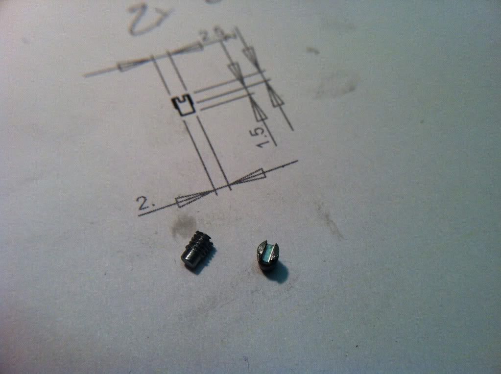
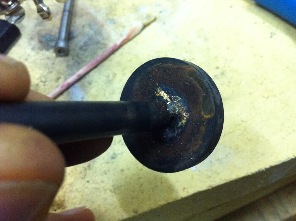
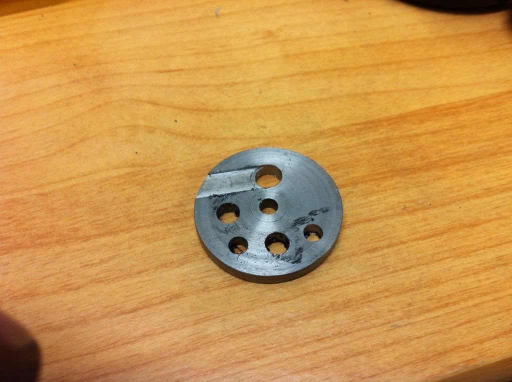
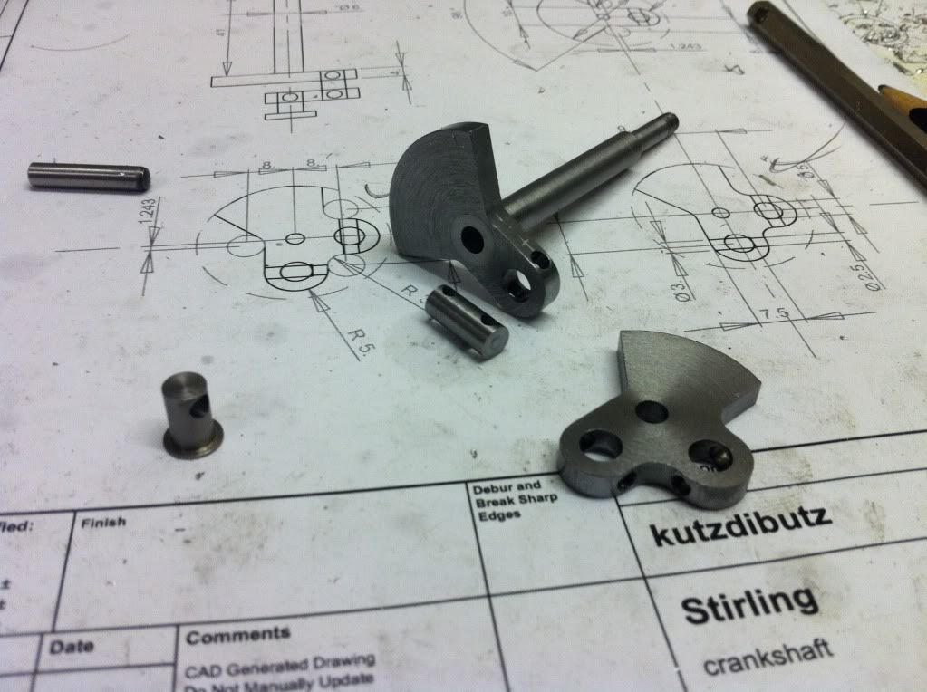
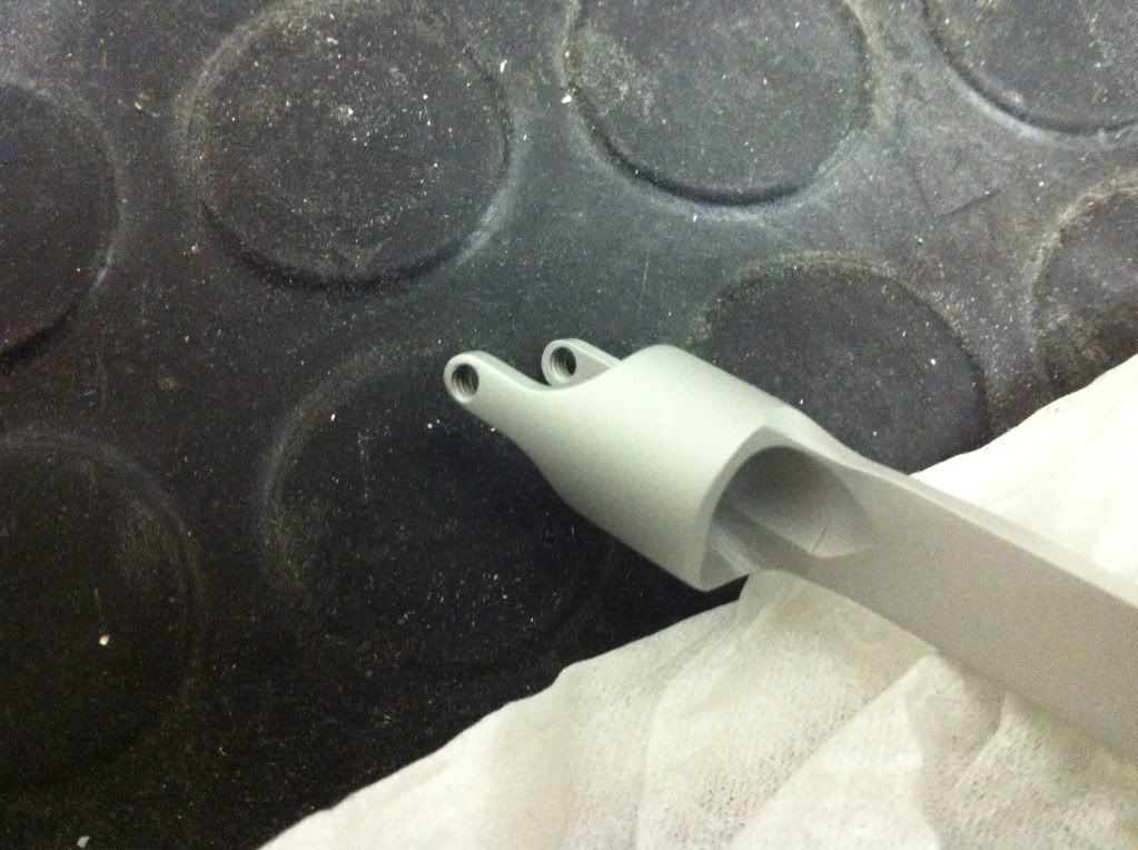
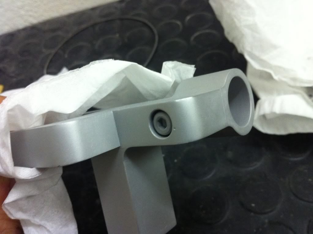
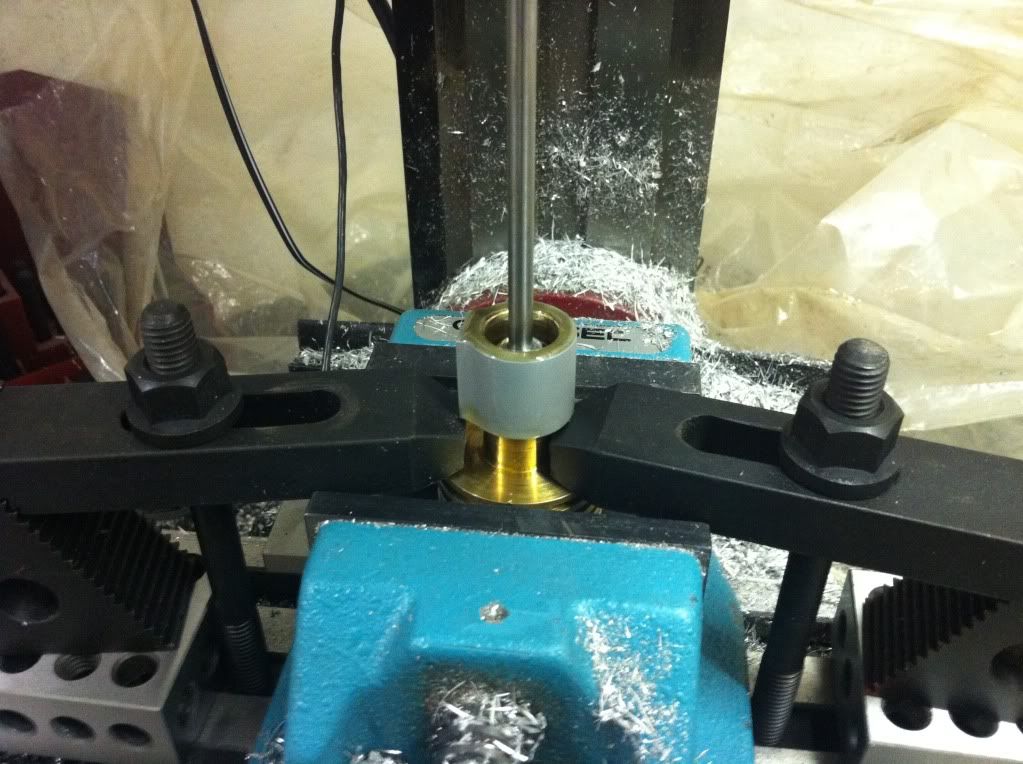
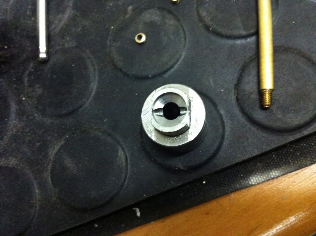
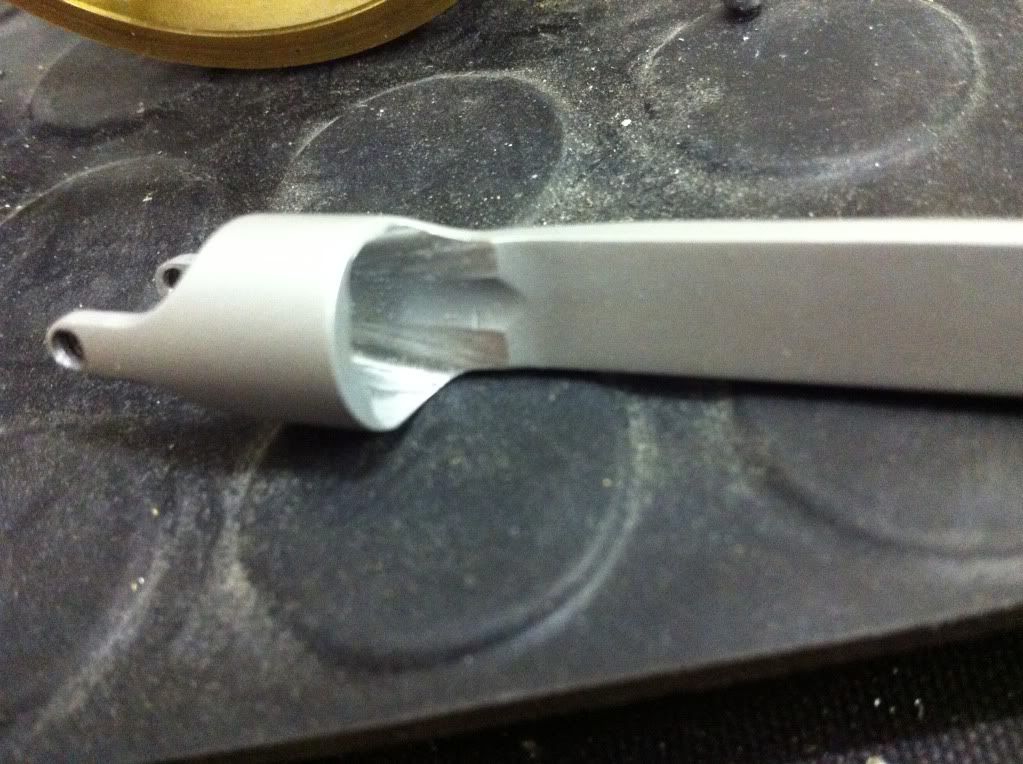
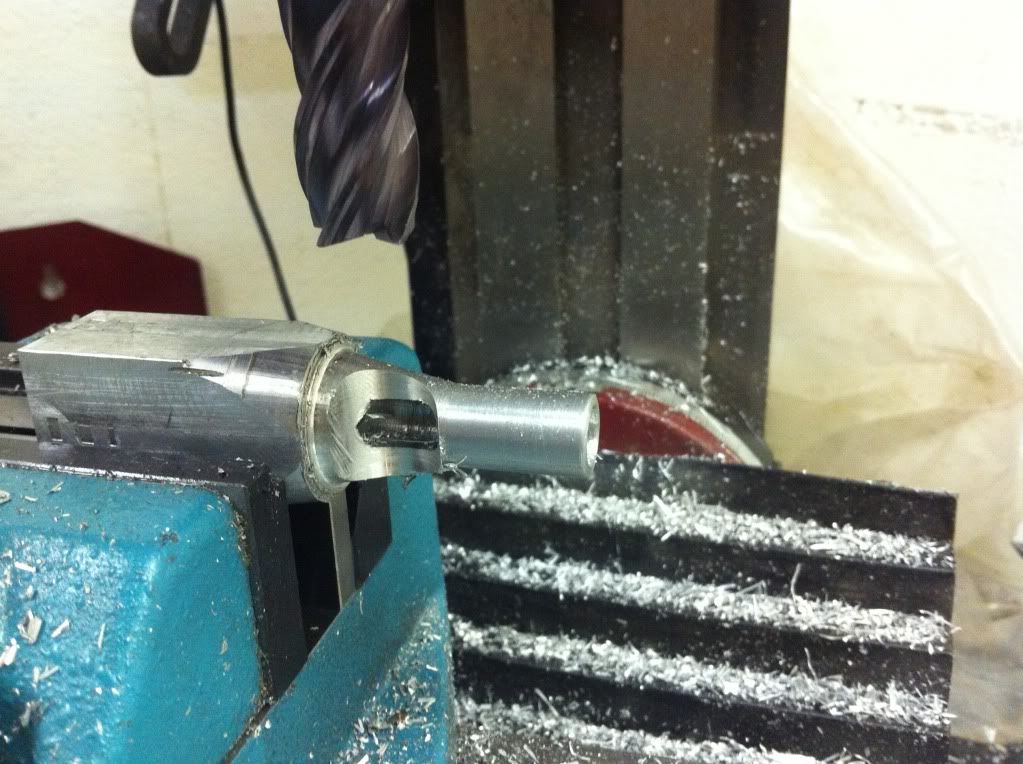
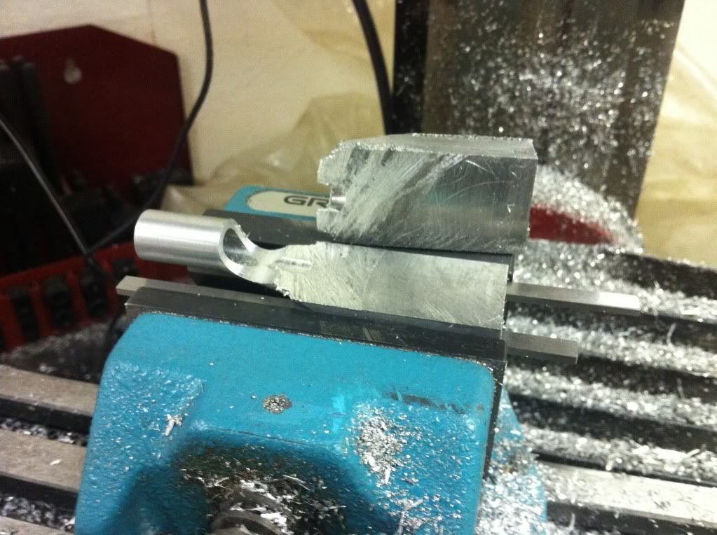
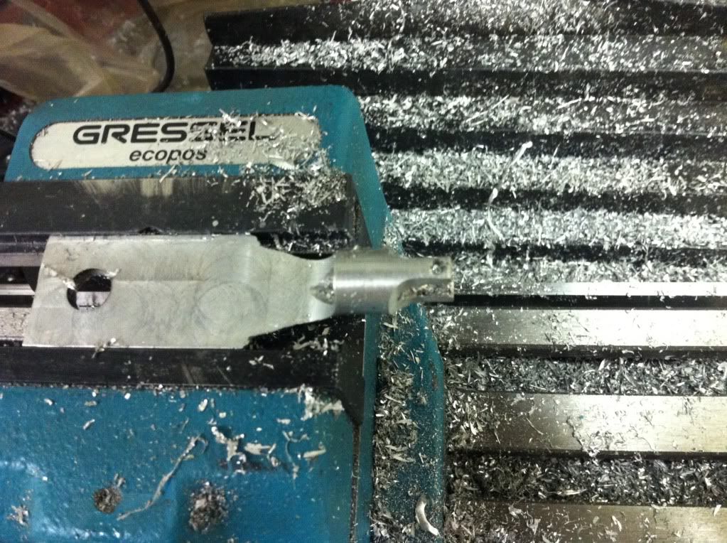
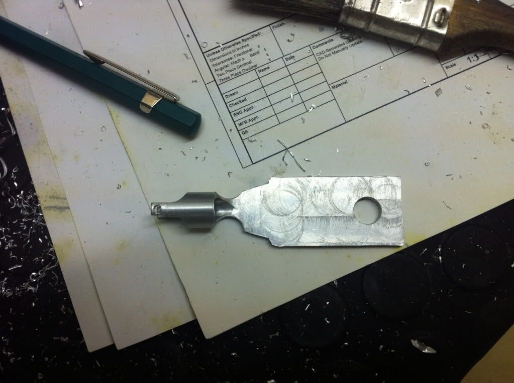
Then drilling the hole and the lathe job for this part is done...

IMG_1079_zpsad1e92d9.jpg


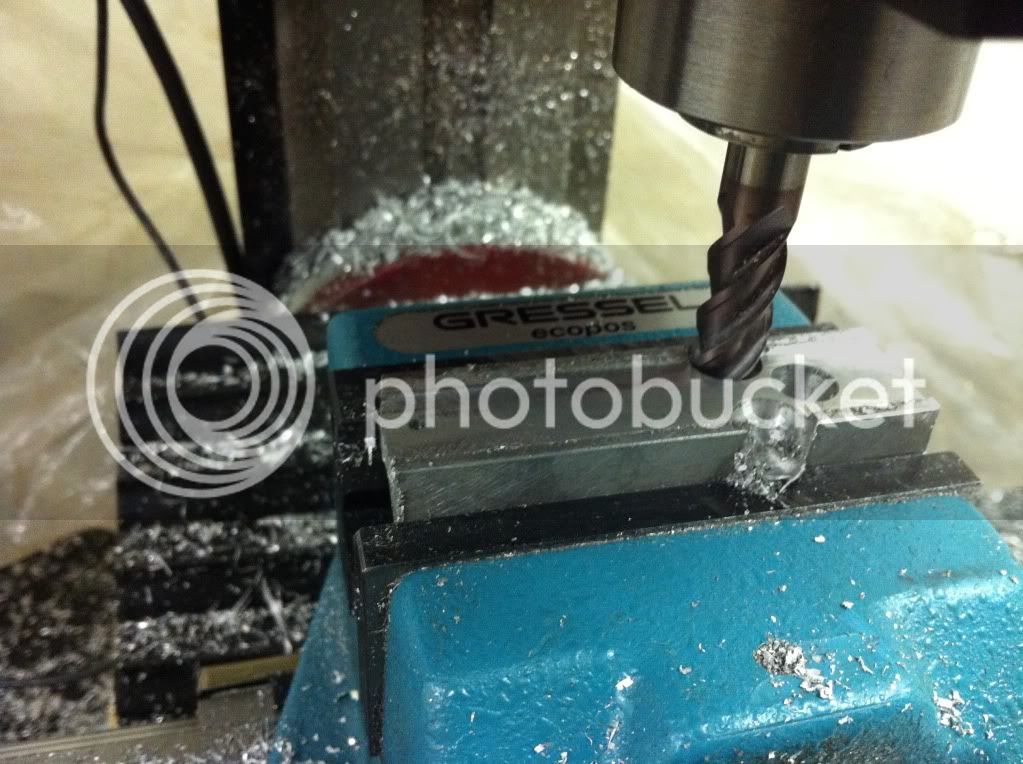
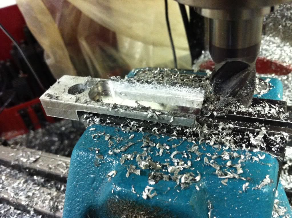
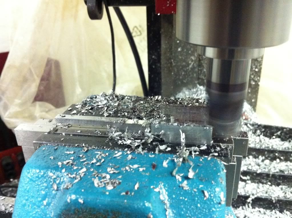
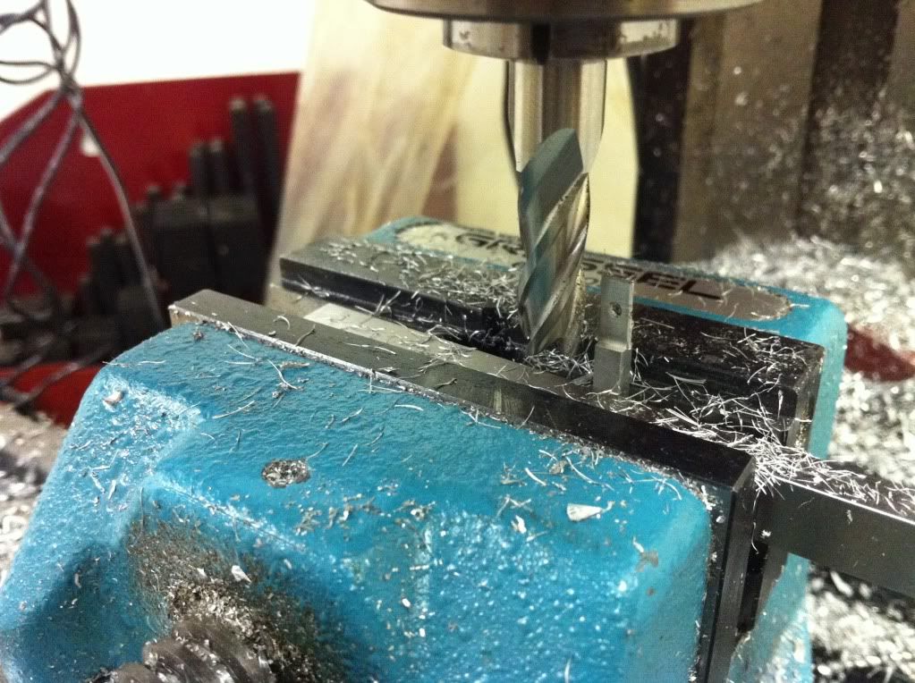
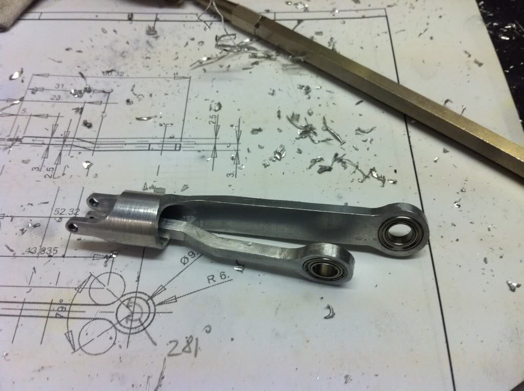
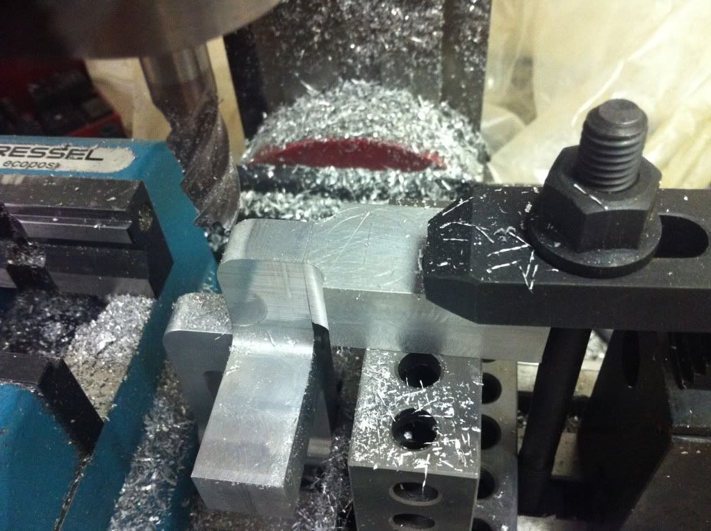
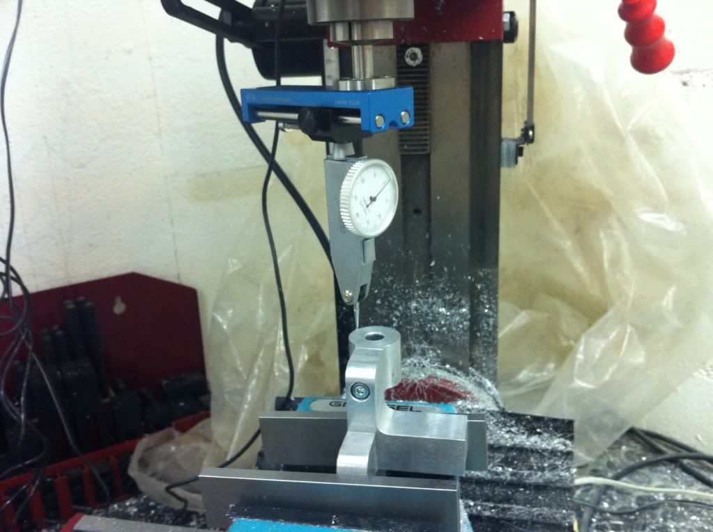
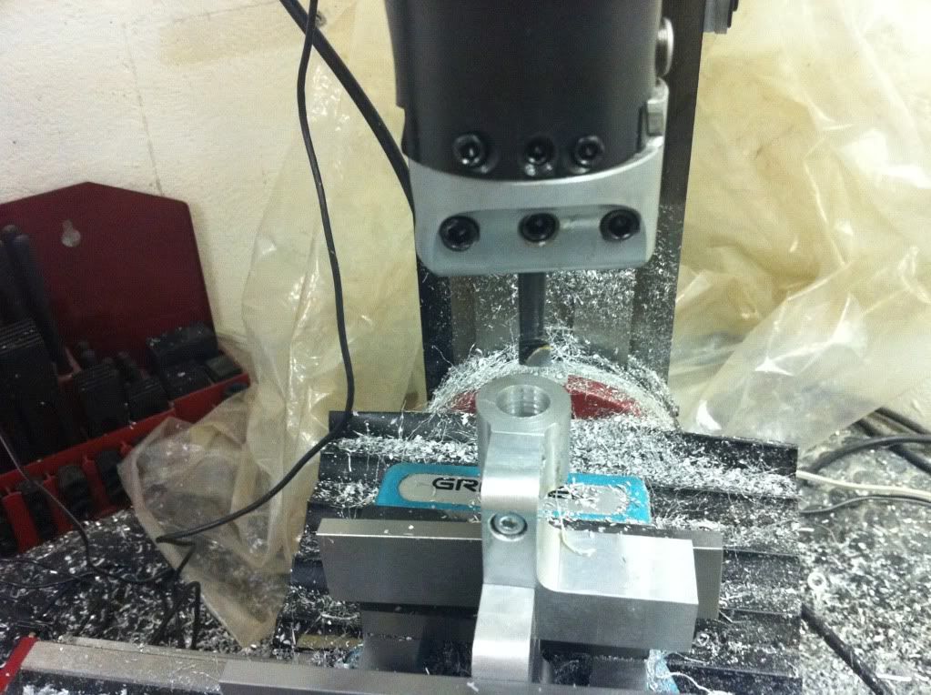
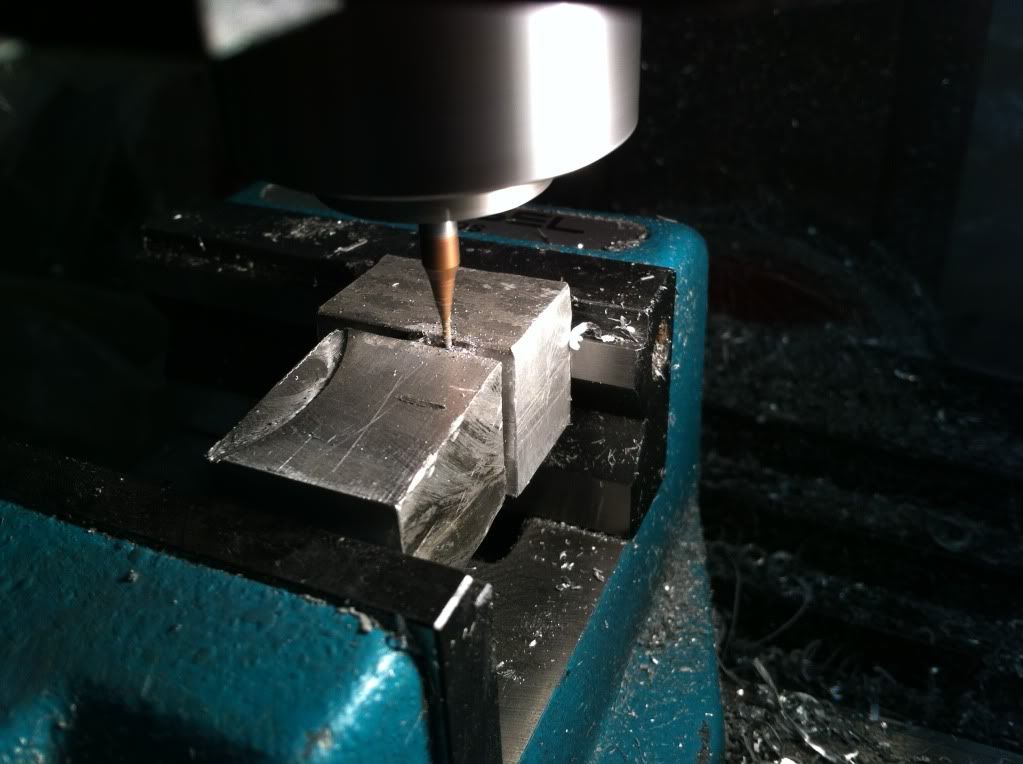
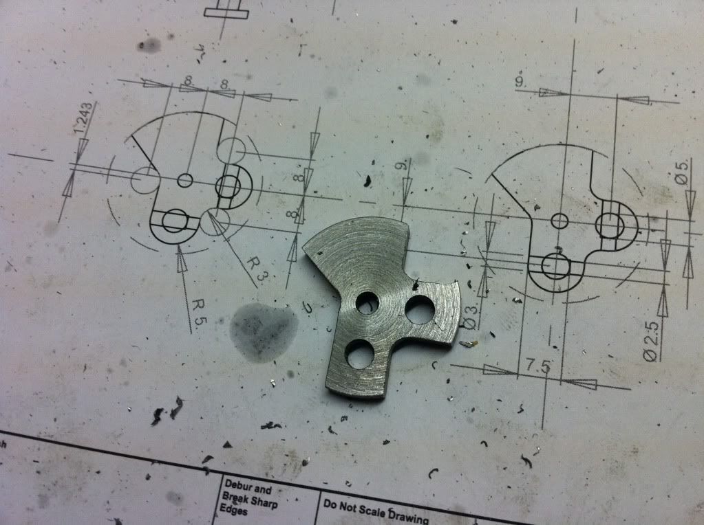
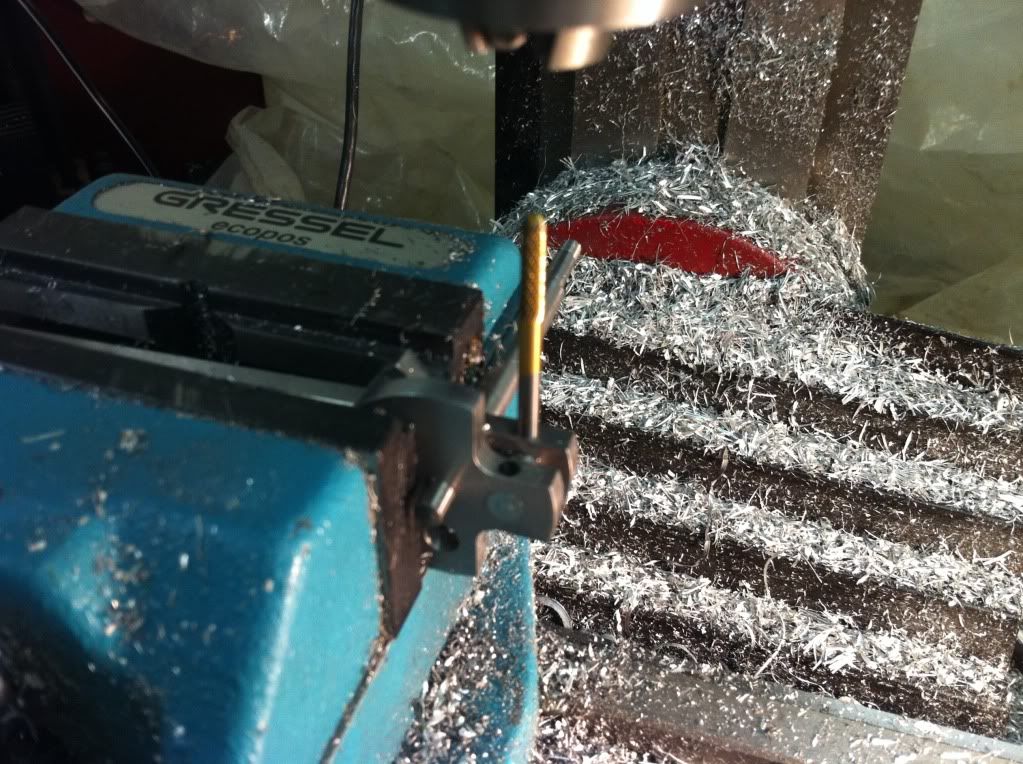
So thats as far as I made it tonight- next fun will be on the mill again...

Cheers, Karsten
 
Hi there,
the last week I was doing bits and pieces on the main rod:

IMG_1085.jpg


IMG_1086.jpg


IMG_1090.jpg


During the milling operation the entire front end bent- not really surprising but I didnt think of that before... (didnt support the overhanging bit that bent) Luckily that was not such a big deal since I could straighten it by just bending the tip back. I put the tap into the M3 holes for indication how much to bend. (lay it flat on the indexing surface and bend the tip until the shaft of the tap is aligned with the angle bracket) That worked fine so far and the part actually starts to look like on the drawing. ;D

IMG_1092.jpg


[...]


Sooo- today I intended to finish the main rod. There were only some - one would say - easy milling operations to do but I choose to mess the part up with the very first! :rant:

IMG_1097.jpg


I dont know, but somehow I have the feeling that it might be of advantage to read the own drawing and actually follow it... Or make the drawing clearer... I picked the wrong dimension so the lower milled radius is 2mm off measure. The upper one would be the correct position... I think I mentioned that already somewhen- I would really appreciate if someone would invent 'metal-on-milling'!!

Right, off to the scrap bin with this one and start over again. At least the new main rod attempt turned out a bit nicer so far. This time it didnt chatter so much making the cone. Maybe because I trimmed the blank a bit closer to the final dimension of the part. Or I clamped it a bit better- dont know...

IMG_1101.jpg


Hopefully I manage to pick the measures correct now... Lets see...

So long
Karsten
 
Karsten, no, no, don't the photo's there is never to many, its great for someone who don't know how to make some of those cuts, thanks for the extra trouble to photo, Lathe Nut
 
Karsten, I find marking out a workpiece helps avoid machining the wrong part away. Even when I use the dials to place the cut there is always a line there to confirm. Marking out takes a while, but once you are used to the process, not too long.

Watching parts emerge from the solid is always fun so keep posting the pics:)
 
Hi folks,

thanks for the comments- this always gives some motivational boost!
@ProdEng: yes, I really have to get this into me, that so makes sense to have markings. I kind of skipped it mainly because I didnt think of that but also- at least for a small fraction- to move on. Where this can end up becomes quite obvious... ;)

So and while I was silent around here I was busy somewhere else. At least for the time I could spare.
This time I changed the sequence a bit to avoid the bending of the front bit. I machined everything of the fork thingy that connects to the piston later on. So here we are ready to mess up again...
IMG_1114.jpg


And guess what- this time it worked allright, because I payed extra attention... And there are even some lines I put by coincidence, because this was before I recieved the hint.. ;D

IMG_1115.jpg


Next up I milled the pocket needed as clearance for the displacer rod. So I set it up with an angle of 10°. With the result I'm only moderately happy- I did nicer cuts before... But this is 'inside' the rod and will be barely visible when running.

IMG_1116.jpg


IMG_1117.jpg


For cleaning off the excess material along the shaft of the rod I used some mill shafts, a parallel and some blue loctite for the setup. The parallel I removed once clamped in the chuck.

IMG_1120.jpg


Milling the 'ring' around the bearing I had some mishap again. I was doing a too enthusiastic cut and the part was ripped of the pin and bent the rear part all over. The idea of a photo was lost inbetween the swearing, grabbing the hammer and whacking it back into shape. So the bore for the bearing was not round anymore and also too wide. After a short cofferoom discussion with a friend the solution was more or less clear. Gently gently pressing the ring at 3 locations should give a snug fit for the bearing again. So give it a shot...

IMG_1126.jpg


That worked, the bearing is now sitting tight again.
Final touch was the radii on the fork thingy- this I did with a bit of patience by hand. Deemed it too risky machining that...

IMG_1122.jpg


So thats it, part done. Pheeww....

Cheers, Karsten

PS: the displacer rod is also finished, I will sum that up a little later (today maybe, or tomorrow...)
 
Hey there,

for the displacer rod I started off with a squared blank again. First the holes for the bearing and the conneciton pin and then milling the rough shape:

IMG_1127.jpg


IMG_1130.jpg


Then flipping it over and getting the rear side to the required measure.

IMG_1131.jpg


IMG_1133.jpg


IMG_1134.jpg


Milling the ring for the bearing I was much more careful and that worked. One side of the angled part I could mill quite easy, for the opposite bit I couldnt really clamp it in the vise. It wasnt sooo much, so I filed it.

IMG_1135.jpg


Finally there was only the reduction at the front bit left and again filing the dradius. Too delicate for me and machining, and too fast and easy done by hand...

IMG_1139.jpg


So there it is- finished parts are always nice, especially when they look pretty much as intended... :) And slowly its coming together...

IMG_1140.jpg


IMG_1141.jpg


So thats all I can report so far. Next up will be the crankshaft stuff. Looking forward to it.

Cheers, Karsten
 
Hi there again,

some collective update from the last couple of working sessions.
I was a bit fast in saying that it would be down to the crankshaft yet... First there was another piece to be attached to the main body:

IMG_1144.jpg

Holes for the positioning pins and in the center the M4 tap.

IMG_1145.jpg


Next I properly clamped the piece on the mill and machined the two radii.
(still need to get a proper pen or paint for better visibility of the markings...)
IMG_1153.jpg


After that I drilled the starting hole where the cylinder will be sitting later and rounded off the outer contour.
IMG_1160.jpg


There were times where my fingers were dangeroulsy close to the fast spinning mill. Definetly out of my comfort zone but I proceeded with the awareness of the extra extra attention to be paid during this operation. I got away with it allright but would be grateful if someone has a hint how to make such things in a safer way. :hDe:

Next was the bore for the cylinder. So I found the center with the dial indicator on the outer contour. Then slowly and patiently increasing the diameter step by step.

IMG_1163.jpg


IMG_1164.jpg


Done that there was disassembly time again to salvage the parts to be re-used. I really wondered why the heck I soldered the cylinder THAT well to the holder... Too much for the small lighter torch but no problem for the bigger one. :cool:

IMG_1159.jpg


So here we have the collection of scrap material:
IMG_1167.jpg


The re-use:
IMG_1168.jpg


And the new parts so far:
IMG_1169.jpg


Next will be some small parts to connect the rods to the piston and displacer and then finally the crankshaft...

Cheers, Karsten
 
oh boy- just spent hours and hours realising how presistant and unforgiving little machining imperfections are when it comes to a nice and even suface finish... :wall:
So my fingers were getting silver while filing and sanding the aluminum parts. An the annoying bit- its not done yet. Still some way to go, quite done with the file, but more time to be spent with the fine grit... (where is that smiley with the beard growing??)

Cheers, Karsten
 
A few hours spent filing and sanding will certainly help you to get a better machined surface next time, it worked for me !!!
 
A few hours spent filing and sanding will certainly help you to get a better machined surface next time, it worked for me !!!


LOL!! So true Jan! Definetly taught me a lesson- if I actually learned enough by this I'll see at the next try...
 
Last edited:
Hi,

so the work with the file took again longer than expected. I thought I was done but then spent another evening... But it was worth it. Not only is the result better, but it also gave me enough time to get the idea to ask around in our material lab at work if I could sandblast the parts. That shortened the one or two evenings with filthy hands and sand paper to 15min during lunchbreak at the sandblaster! Generally I would be happy with the surface finish if it wouldnt be so damn scratch-sensitive. Even only putting it in the basket for US-cleaning left some marks! Also the water left some traces on the nice and clean surface...
IMG_1196.jpg


So next try will be glass bead blasting which I would have preferred anyway because it wouldnt leave that sharp and pointy peaks on the surface (looking microscopic) but rather smoother dents. Plus it compresses the very outer layer slightly. I just have to be patient enough to wait for the next meeting I have at the site where I could do this. (already phoned the guy in charge :cool: )

In between I will take care about the small parts and the crankshaft- finished the drawings today.

Cheers, Karsten
 
Last edited:
Hi folks,

in the mean time I did some small parts. The connection 'bolts' for the main rod are quite tiny. And I thought to myself- careful with the feed... lol

IMG_1201.jpg


2nd try worked better, but I messed up again trying to cut the screwdriver slits by hand. Even with my thinnest Dremel-disk I was grinding the entire thing down and the groove was nowhere near usable.

IMG_1204.jpg


FAIL- repeat...

This time I milled the slits- that worked better. Using some cut off aluminum as soft brackets, and the final product:

IMG_1211.jpg


IMG_1212.jpg


Now thats acceptable...

So long
Karsten
 
Hi,

next on the list is the crankshaft. In order not to produce an excessive amount of swarf I gave it a shot soldering the shaft. More or less 1st try but if one never starts, one never will manage that... ::)
So I prepared the shaft and a bigger hunk of material which later form the two crank disks.

IMG_1213.jpg


I used some white flux, brass solder and two torches but the attempt sort of failed. The pieces sticked together somehowbut the wetting of the joint was really poor. It survived the parting of the two disks on the lathe, but cleaning the disk connected to the shaft was too much. The joint gave in. There was still enough force to keep the parts together- way enough for the power of the stirling, but I wanted it better, so next try:

IMG_1216.jpg


Ready for fore again

IMG_1217.jpg


The result was moderate again. No wetting through and also no nice fillet.

IMG_1219.jpg


IMG_1220.jpg


And I was melting the solder quite well. The brass was liquid, but was somehow refusing to flow into that gap... Some web research left me with the suspicion, brass solder is not really the way to go. Soldering temperature of 800-1000°C is quite a call... I will get silver solder, around 600°C is more do-able. So I guess the flux was burnt before the brass was liquid... Anyway, the piece survived the cleaning on the lathe, good enough for the later requirements to the part...

IMG_1221.jpg


IMG_1222.jpg


And here we have another good example why marking the part is quite a good idea- one hole again on the wrong side of the center line. FAIL- repeat. I will learn this eventually... :hDe:

IMG_1223.jpg


Now thats better:

IMG_1224.jpg


to be continued...
 
back again, I broke up the post to imit the number of pictures...

The center hole in parts I use for proper referencing on the machine as well as mounting guide. The holes are reamed to 4mm and I use a positioning pin later for alignment during machining.

IMG_1225.jpg


IMG_1226.jpg


IMG_1245.jpg


So here we have the parts of the crankshaft:

IMG_1248.jpg


And assembled with the locking pins bolted in:

IMG_1250.jpg


IMG_1251.jpg


So I'm quite happy with that- not far from assembly time! :cool:

Cheers, Karsten
 
woohoo1
Sometimes paitience is payed off! Today I could get access to this glass bead blasting thing and I'm really happy with the result. Silky-smooth surface- excellent! For once I'm not ashamed of close-ups... :cool:

IMG_1254.jpg


IMG_1257.jpg


And woohoo1 again- assembly has officially started!! I'm so curious if everything will fit together as intended...

IMG_1262.jpg


Just didnt have the time to assemble everything today. So far it is quite balanced out, bit heavy on the flywheel side. There is the pistons and fire tube missing. I will go mental if it happens to be fully balanced when complete. That would be just too much of a coincidence. ;D (didnt really pay attention to that detail during design...)

Cheers, Karsten
 
thanks rocketcaver.

Hi folks,

time for an update again... A quite long frustration found an end. During assembly I noticed a minor resistance in the movement of the displacer piston connecting bar. Having had a closer look to the bore through the piston I realised it was not perfect- it had some weird burr inside. So I reamed it to the next diameter which meant I would need a new connecting bar again. And this sucker provided me with some extra grey hair! It ended up too thin and convex but cylindrical and all in different attempts. On top the switch of my grinder was broken and I was running out of sharp tools... (explaining the convex shape) :rant:
Long story short- it took 5 (FIVE!!) attempts to finish this bit!
IMG_1290.jpg


The assembly of the piston and rod was also a bit fiddly and needed some furhter de-burring. But nothing too dramatic.
IMG_1294.jpg


Trying to fit the piston in the cylinder it became apparent that pressing the cylinder into the holder it did something to the dimension of the cylinder itself. So another go looping the part in...
IMG_1295.jpg


But eventually I got so far to have piston and rods assembled.
IMG_1298.jpg


BUT:
I do not know and cant really explain what made think I would only need the pocket for displacer rod clearance on the one side of the main rod... :wall:
IMG_1299.jpg


Yes, clearance is also needed on the other half of the revolution... ts ts ts... Assumptions during design lead to rework.

And there is also some clash that stops a full revolution at the connection of the displacer rod.
IMG_1300.jpg


Fixed both in the mean time- but now I need to go for glass beads once more...

So long
Karsten
 
Very educational post. Thanks for sharing your mistakes and how you fixed them. Great work!

Pat
 
Thanks Pat, I don't mean to be educational- it's just my two penny worth...
(but maybe its the sometimes trial and error that adds some flavour :D )

haha- and talking of errors- did it again... When looking at the 'freed up space' at the piston I realised I was a bit enthusiastic and also freed up most of the hole the piston connects with the rod... There was some material left but very thin and even though a stirling has not that massive power with time that could give in. So I drilled that hole a bit bigger and pressed some brass bushings in. now there is more contact surface for the connection pin to the rod.
IMG_1305.jpg


And looking at the milled pocket at the rod I decided to skip the effort running around for glass beads- I didn't do much damage to the other surfaces and at the end it doesnt look too bad...
IMG_1307.jpg


So I also finished the displacer pushrod to fit the displacer itself. All the movement is free in the revolution. There is only the firetube to be mounted but workshop time was more than up... Plus I want to swap it with a stainless steel version for heat conductivity reason (following a recommendation from the beginning of this thread). Lets see how this machines, otherwise I'll keep the brass version...
IMG_1308.jpg


So happy holidays everyone!
Cheers, Karsten
 

Latest posts

Back
Top