kutzdibutz
Well-Known Member
- Joined
- Feb 16, 2012
- Messages
- 74
- Reaction score
- 28
Hi folks,
2nd project of mine is a stirling engine. One that I once built during an internship at university, where I was allowed for the simple parts. When it was coming to the crucial components the workshop master tapped me on the shoulder saying 'step aside lad, playtime is over, now its important'. And honestly- if he wouldnt have done so, I would have had no chance to finish this those days. (there was only a couple of days left for this)
So the piston, cylinder and fire tube the master did. And watching him do the stuff was very interesting. The flywheel, rods and the small stuff I did myself. But 100% self made is different... Anyways, I was proud like hell when I assembled it and it was running.
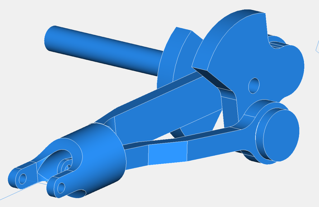
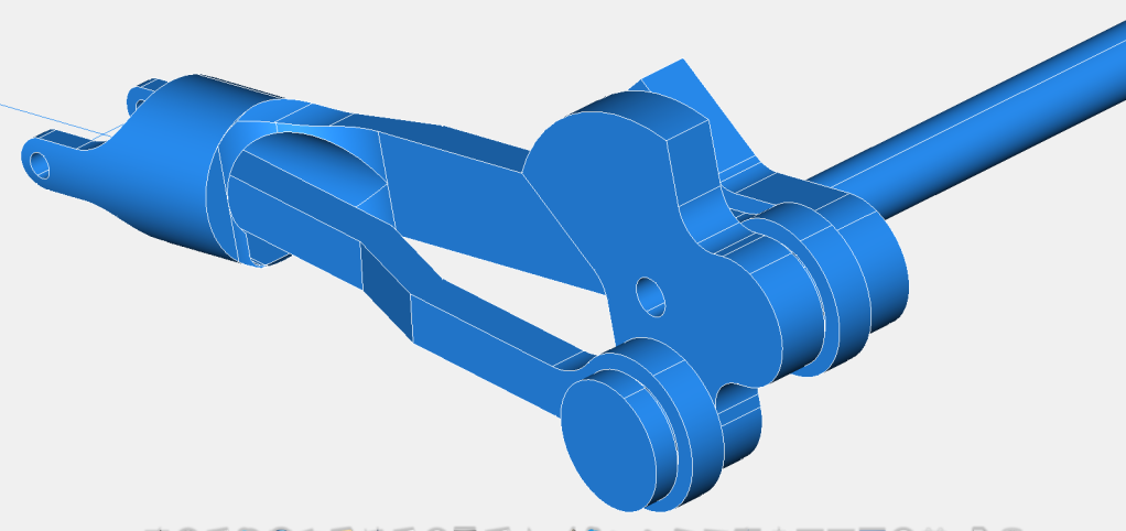
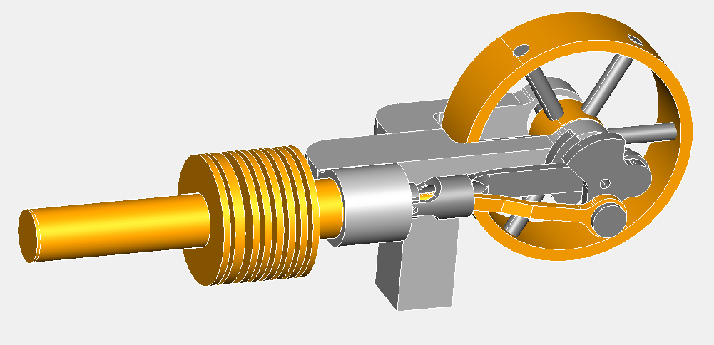
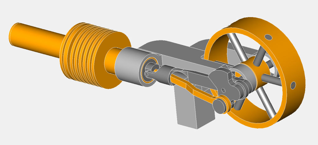
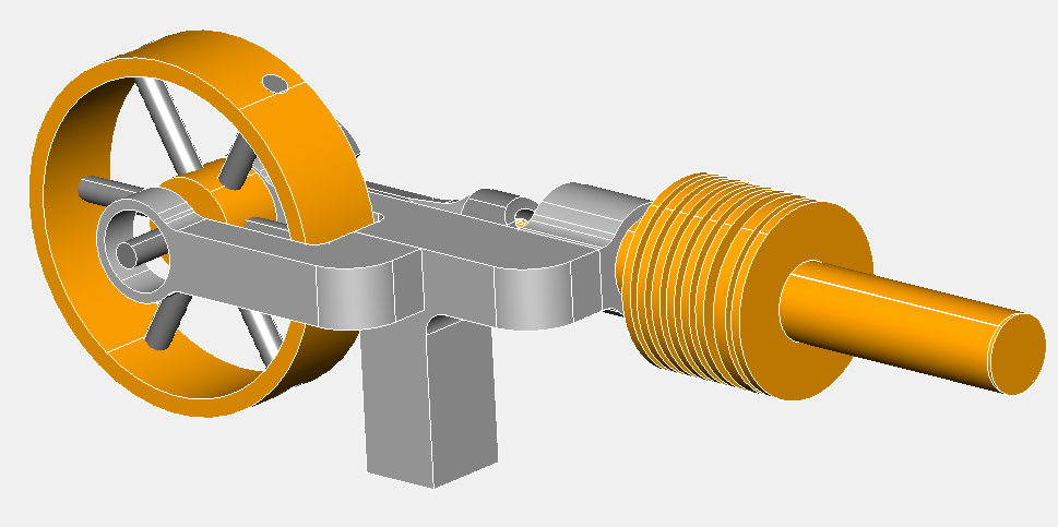
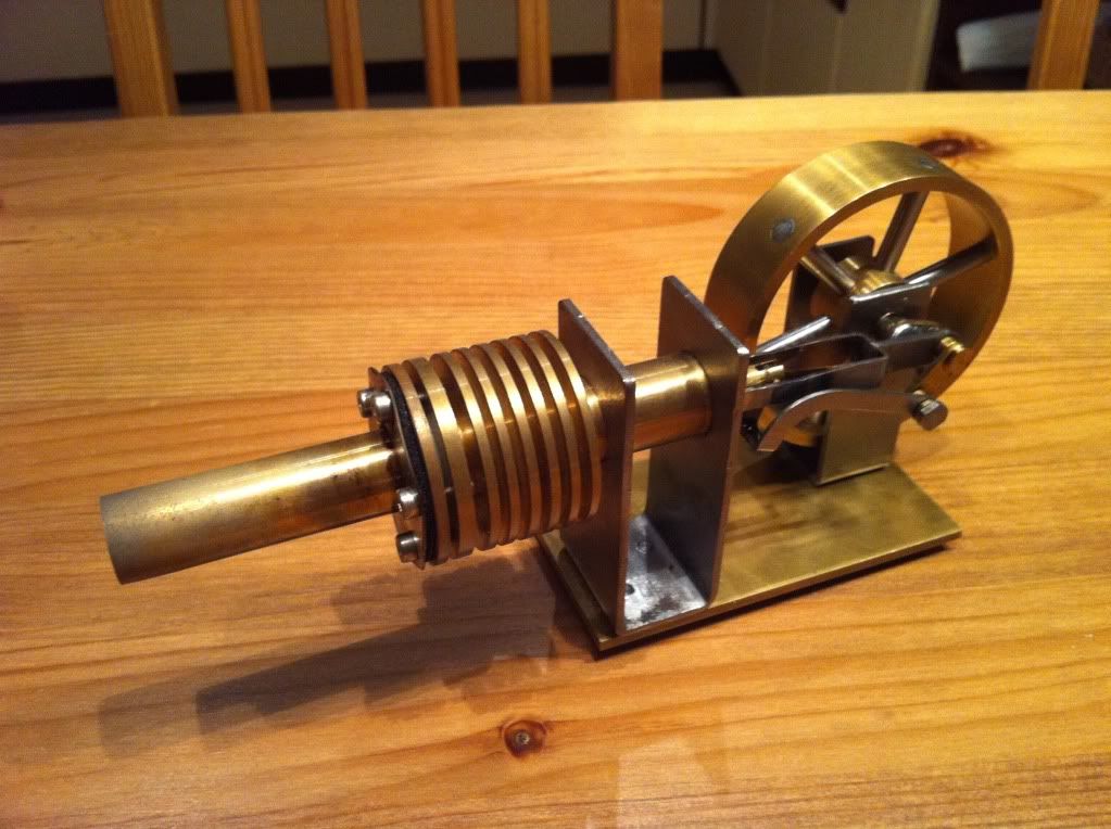
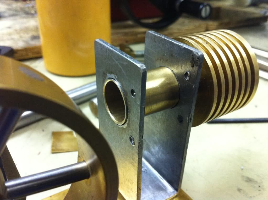
That was the old days. Now having an own workshop I had to re-do this of course. I stayed with the basic design, however modified the plan slightly. The cooling ribs I choose to machine, the piston diameter I increased so it would fit the material I had and I would only need to cut the length (so I thought) and the flywheel design I changed also to the material available. The build proceeded and eventually I was done.
BUT: that bloody thing didn't run! (of course)
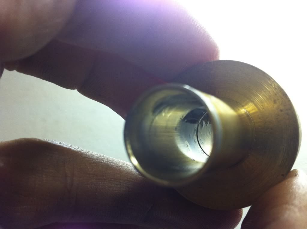
During machining of the cylinder I carefully watched the progress. The tool was cutting the brass nicely but at the final diameter I checked with the piston. I was still a bit tight so I choose to just have another go without feeding but this was already too much! Too much play of piston and cylinder and naturally the sealing was more than poor... :wall:
So I didn't want to spend the effort of making a new piston and no new cylinder either. Instead I made some PTFE piston rings. So the sealing definitely improved, but now the friction was way to high. Next to that issue the mechanics had some blockage which I removed by taking off the 'intersecting' material. But still, a no runner... Even though I tried to loop it and thought it would run reasonably smooth the friction increased again when heating up, since PTFE as a higher expansion rate than the other material (brass and steel).
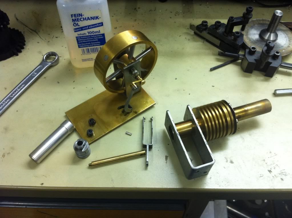
With this I had the stirling sitting for a while and did some long needed machine maintenance and modifications. Done that I came back to the stirling. (there was enough time in between to be motivated again do deal with it) After the unsuccessful attempt with the PTFE and several other fails trying to squeeze the piston to gain some diameter by deformation or trying to create some burr (silly me...) it became fairly obvious that its time for a new piston. So disassembly time...
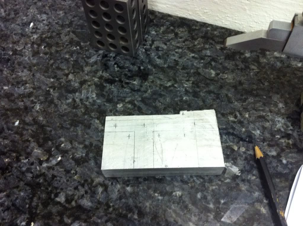
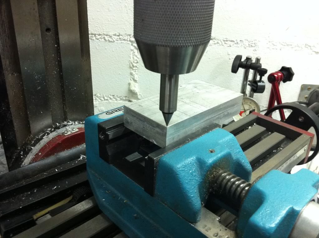
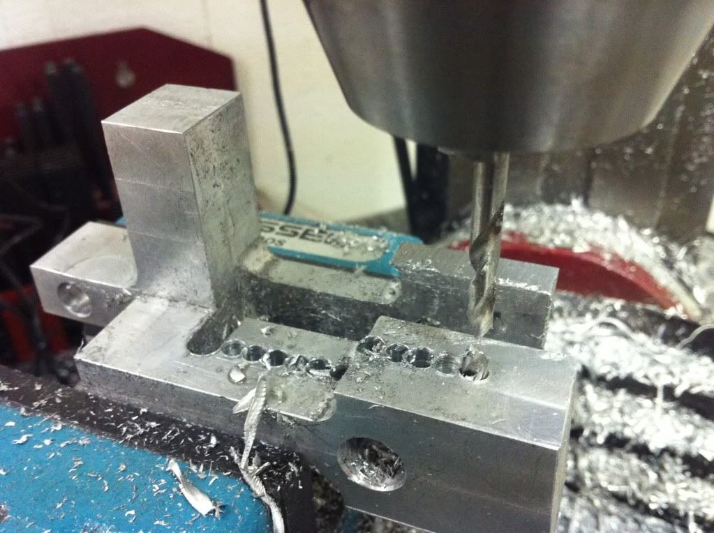
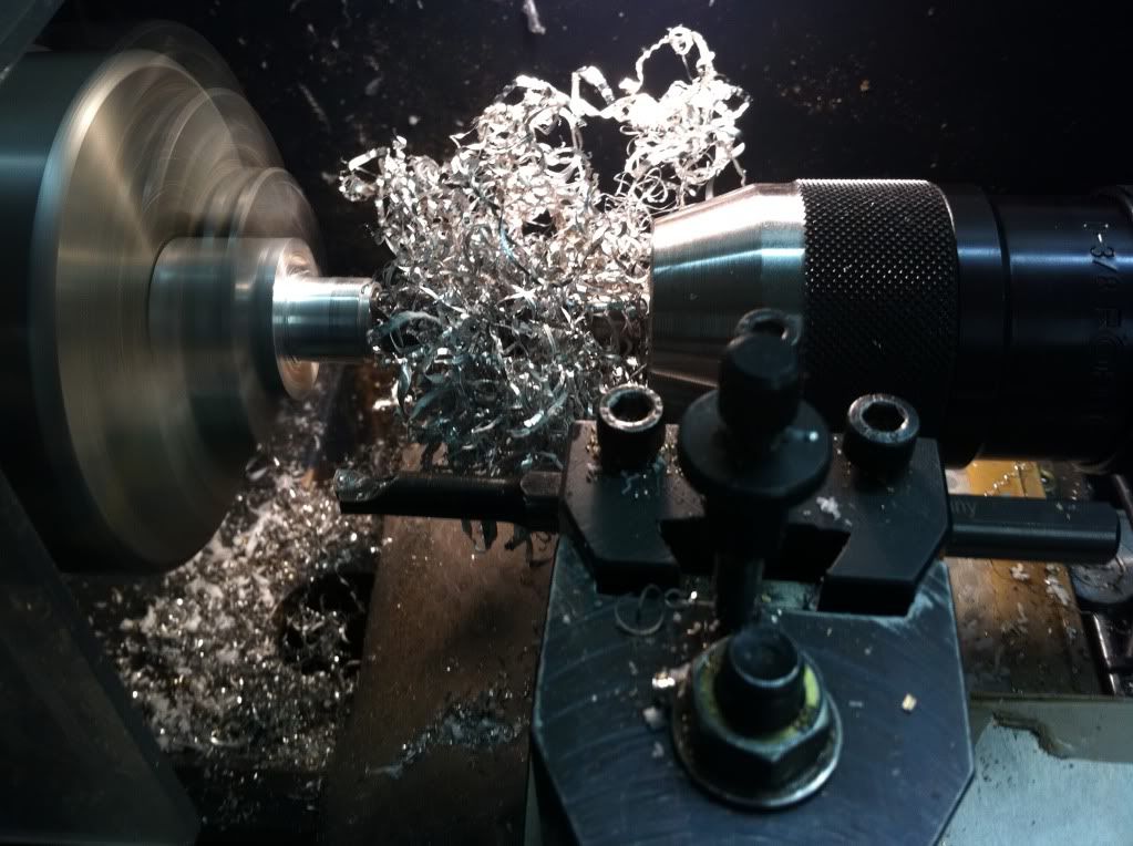
First try, settings of the newly installed DRO wrong by 1mm, and it ended up off dimension- and of course too thin... (Murphy, you bastard!! :rant: )
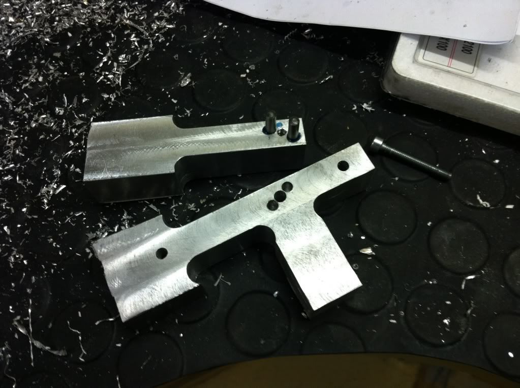
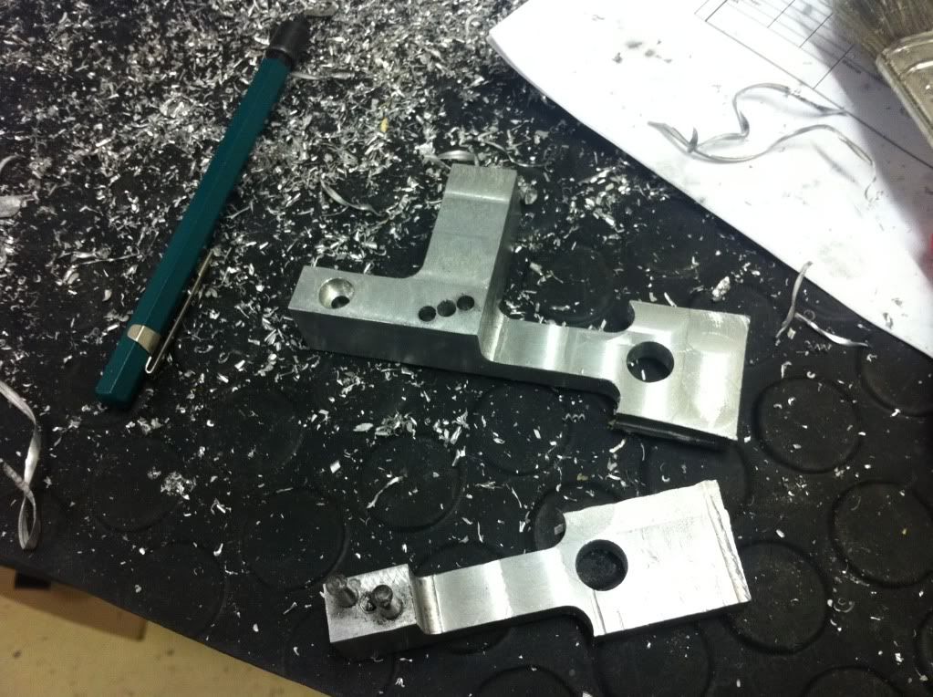
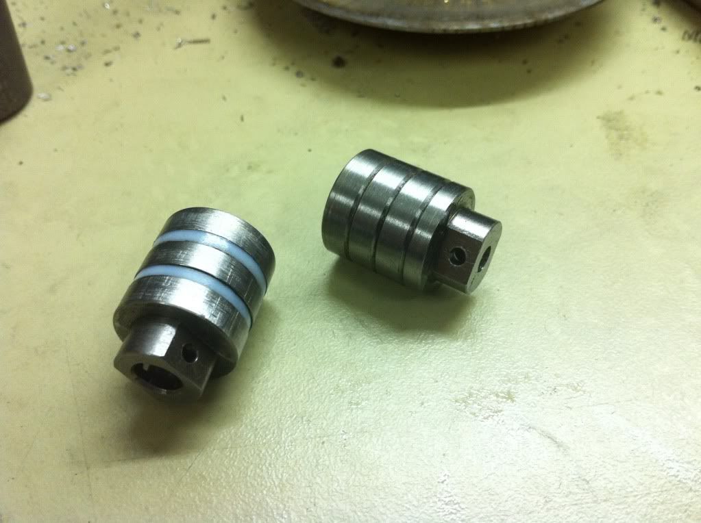
2nd try, correct settings and there it is- left: the old bugger, right: the new guy.
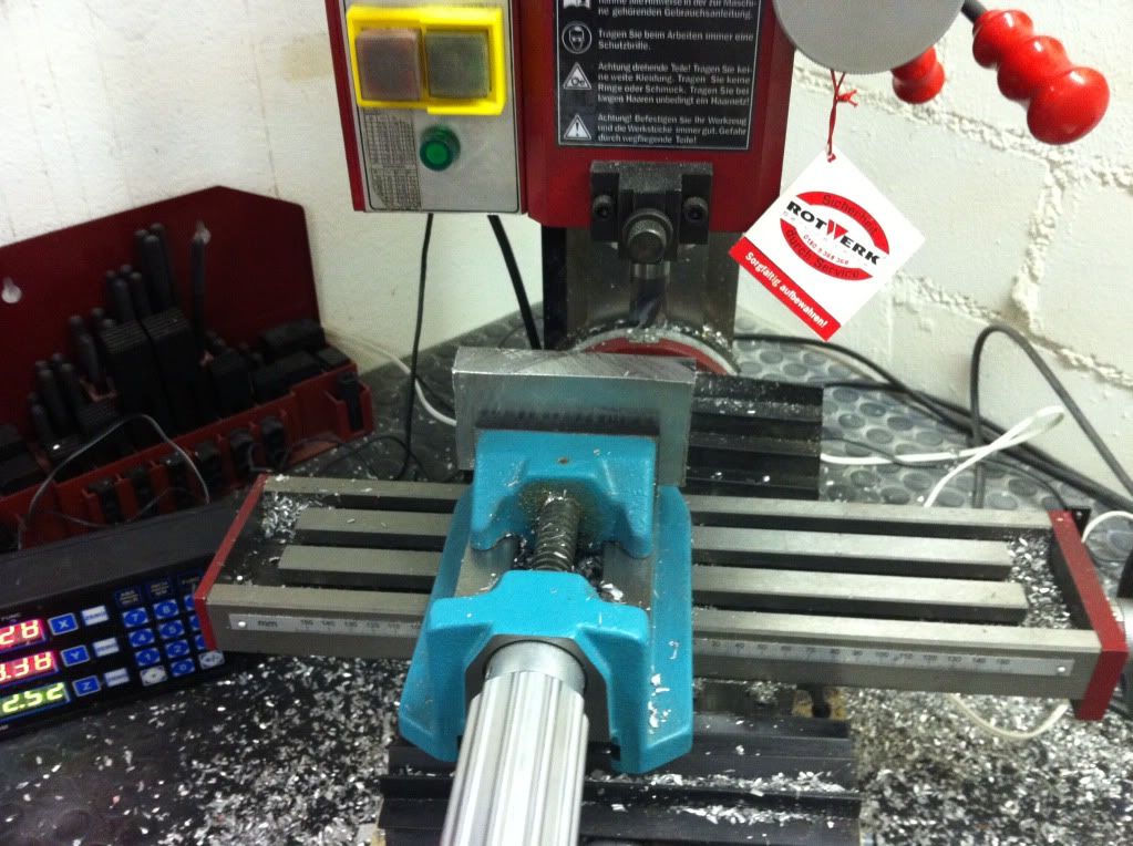
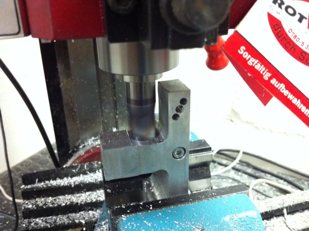
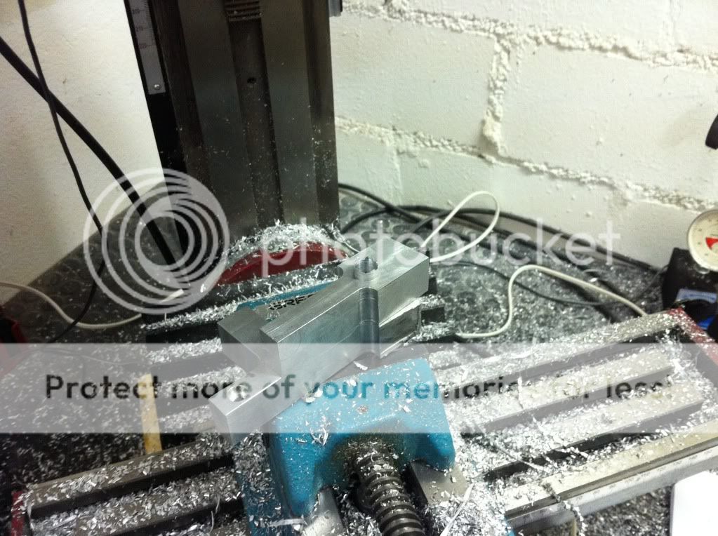
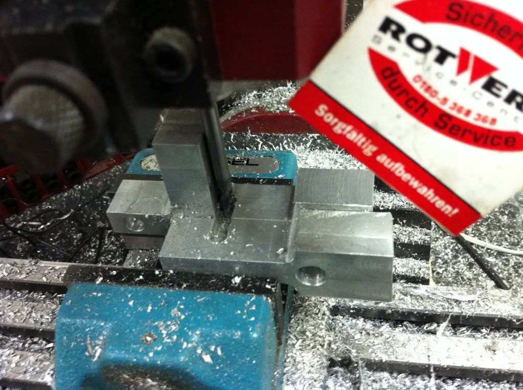
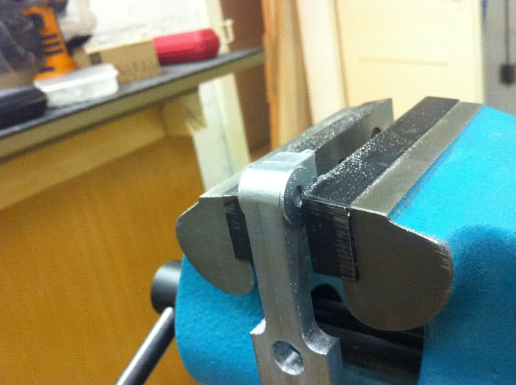
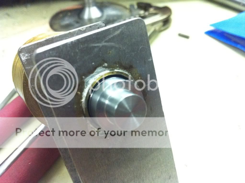
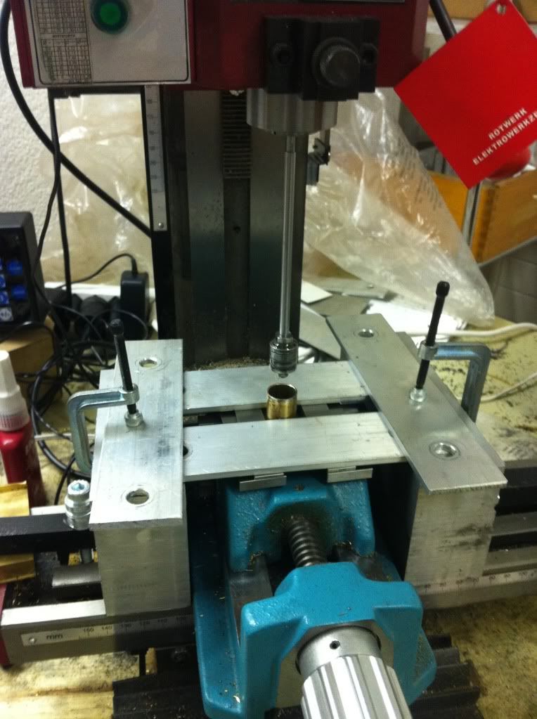
The looping in setup: ('misused' the mill a bit)
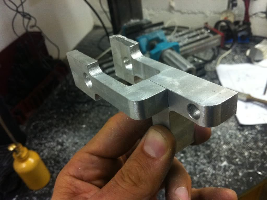
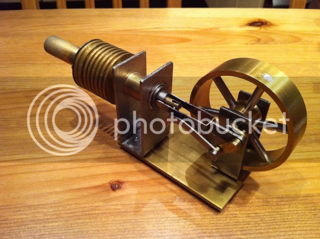
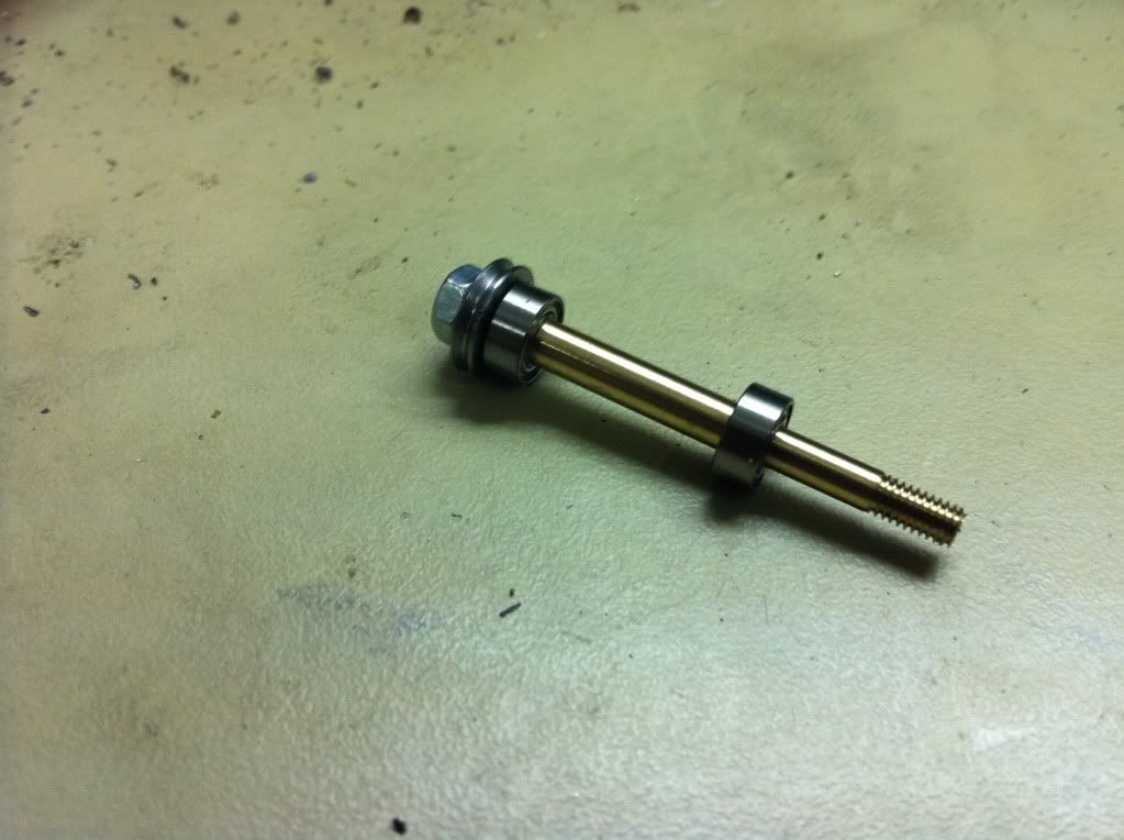
and the final product
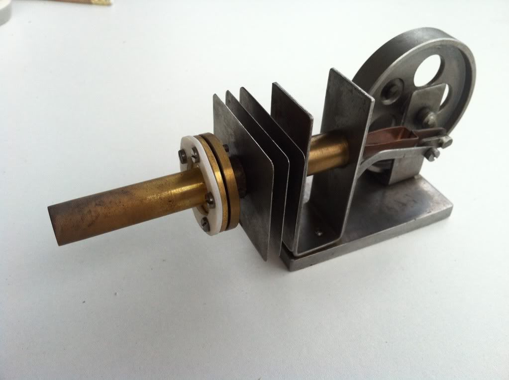
So while having the Stirling disassembled it was time to think about an upgrade and performance improvement:
Some fan cooling should do the job... But first it should run at all... (which it still didnt- neither with nor without the fan)
With the new piston it was smoothly turning, no blockages in the mechanics, reasonably good sealing, not too much friction, correct timing. In other words- no reasonable excuse not to run... And heating it up one could see it wanted to- but there was some sort of lack of energy...
Some head-scratching later I realised I increased the piston diameter and consequently also the displacement piston. BUT: Apparently I should also have payed attention to the V-O-L-U-M-E increase of the displacement piston. I didnt start the big mathematics but made the 'extension' fitting to the room available.
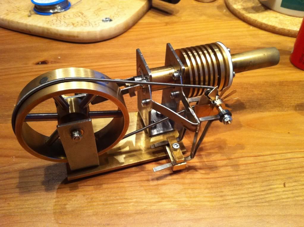
Assemble, fire it up and bingo- we got ourselves a runner!

However the self proclaimed performance upgrade consumes more than it delivers. So there is clearly room for improvement and plans are flying around in my head.
Another huge improvement potential is the overall design, which turned out way more bulky than acceptable at the end. Mental note: get rid of all the bent and soldered sheet metal and make something proper. But at the moment time is rare- so lets see when there will be an update on that one.
Cheers, Karsten
2nd project of mine is a stirling engine. One that I once built during an internship at university, where I was allowed for the simple parts. When it was coming to the crucial components the workshop master tapped me on the shoulder saying 'step aside lad, playtime is over, now its important'. And honestly- if he wouldnt have done so, I would have had no chance to finish this those days. (there was only a couple of days left for this)
So the piston, cylinder and fire tube the master did. And watching him do the stuff was very interesting. The flywheel, rods and the small stuff I did myself. But 100% self made is different... Anyways, I was proud like hell when I assembled it and it was running.
That was the old days. Now having an own workshop I had to re-do this of course. I stayed with the basic design, however modified the plan slightly. The cooling ribs I choose to machine, the piston diameter I increased so it would fit the material I had and I would only need to cut the length (so I thought) and the flywheel design I changed also to the material available. The build proceeded and eventually I was done.
BUT: that bloody thing didn't run! (of course)
During machining of the cylinder I carefully watched the progress. The tool was cutting the brass nicely but at the final diameter I checked with the piston. I was still a bit tight so I choose to just have another go without feeding but this was already too much! Too much play of piston and cylinder and naturally the sealing was more than poor... :wall:
So I didn't want to spend the effort of making a new piston and no new cylinder either. Instead I made some PTFE piston rings. So the sealing definitely improved, but now the friction was way to high. Next to that issue the mechanics had some blockage which I removed by taking off the 'intersecting' material. But still, a no runner... Even though I tried to loop it and thought it would run reasonably smooth the friction increased again when heating up, since PTFE as a higher expansion rate than the other material (brass and steel).
With this I had the stirling sitting for a while and did some long needed machine maintenance and modifications. Done that I came back to the stirling. (there was enough time in between to be motivated again do deal with it) After the unsuccessful attempt with the PTFE and several other fails trying to squeeze the piston to gain some diameter by deformation or trying to create some burr (silly me...) it became fairly obvious that its time for a new piston. So disassembly time...
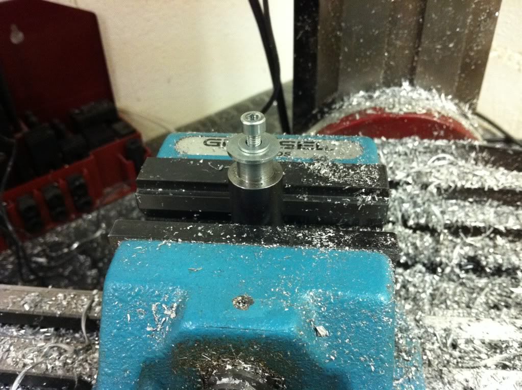
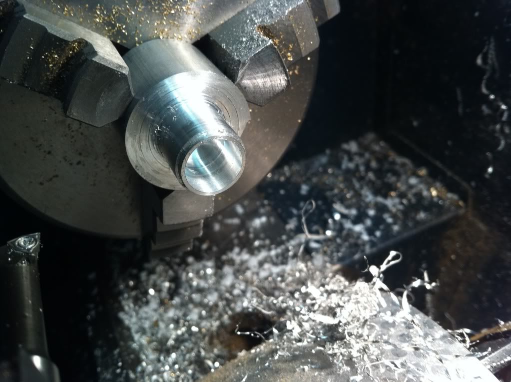
First try, settings of the newly installed DRO wrong by 1mm, and it ended up off dimension- and of course too thin... (Murphy, you bastard!! :rant: )
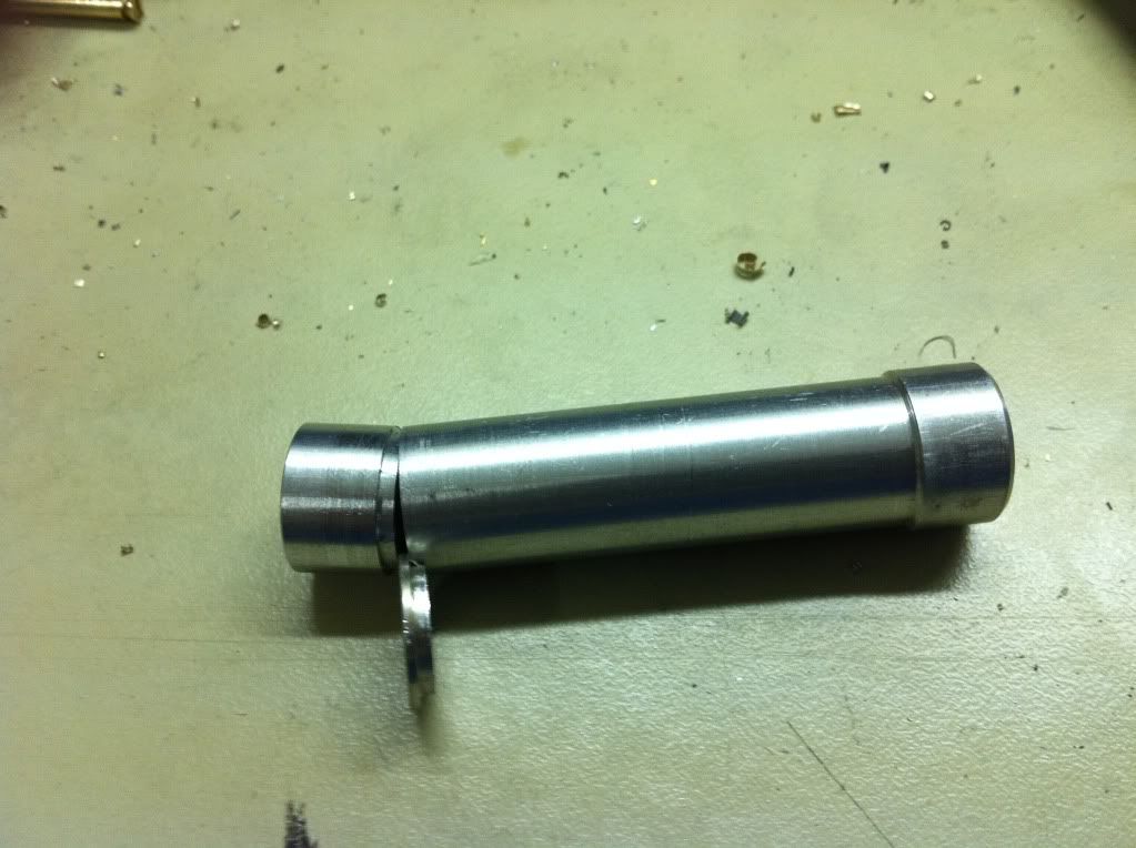
2nd try, correct settings and there it is- left: the old bugger, right: the new guy.
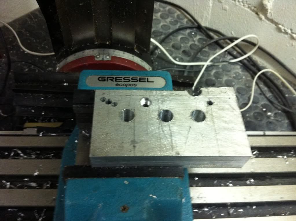
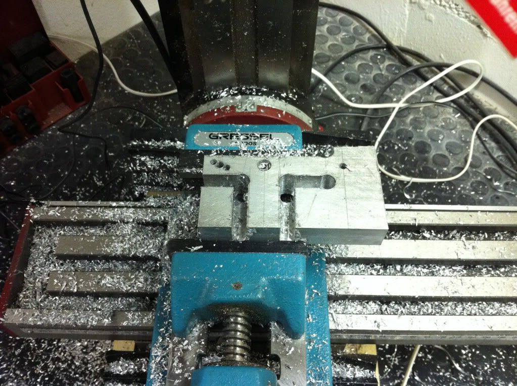
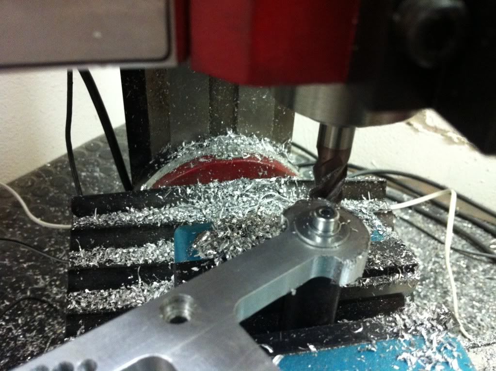
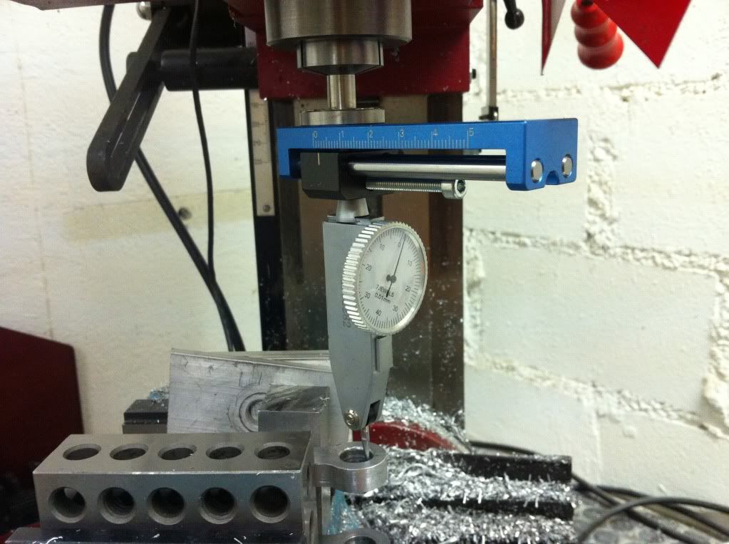
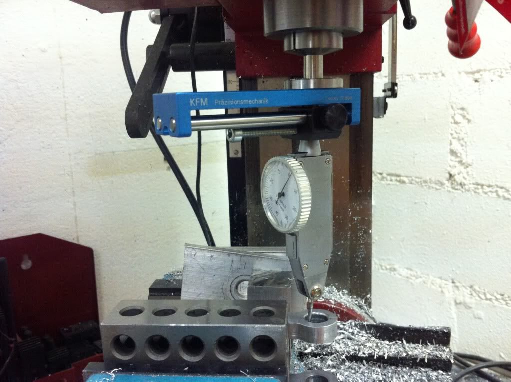
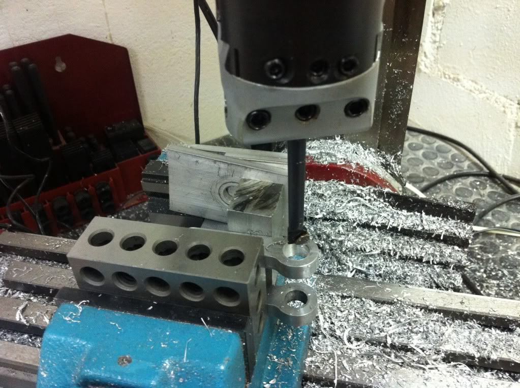
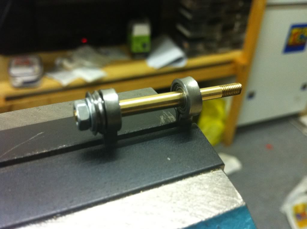
The looping in setup: ('misused' the mill a bit)
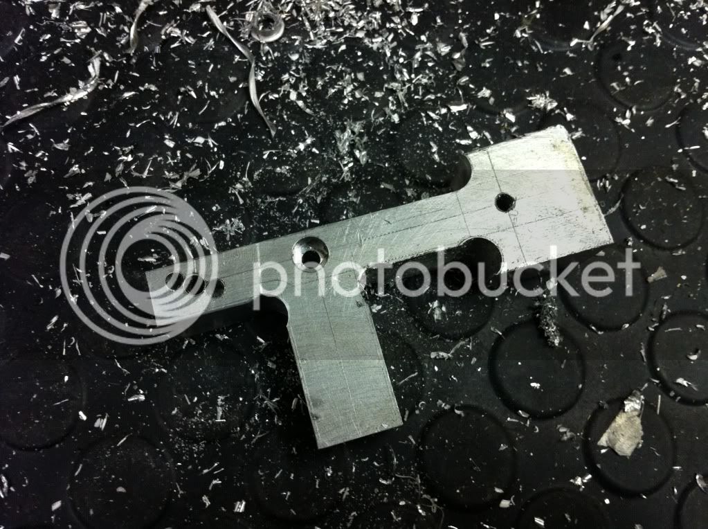
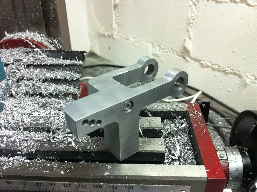
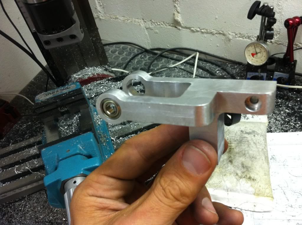
and the final product
So while having the Stirling disassembled it was time to think about an upgrade and performance improvement:
Some fan cooling should do the job... But first it should run at all... (which it still didnt- neither with nor without the fan)
With the new piston it was smoothly turning, no blockages in the mechanics, reasonably good sealing, not too much friction, correct timing. In other words- no reasonable excuse not to run... And heating it up one could see it wanted to- but there was some sort of lack of energy...
Some head-scratching later I realised I increased the piston diameter and consequently also the displacement piston. BUT: Apparently I should also have payed attention to the V-O-L-U-M-E increase of the displacement piston. I didnt start the big mathematics but made the 'extension' fitting to the room available.
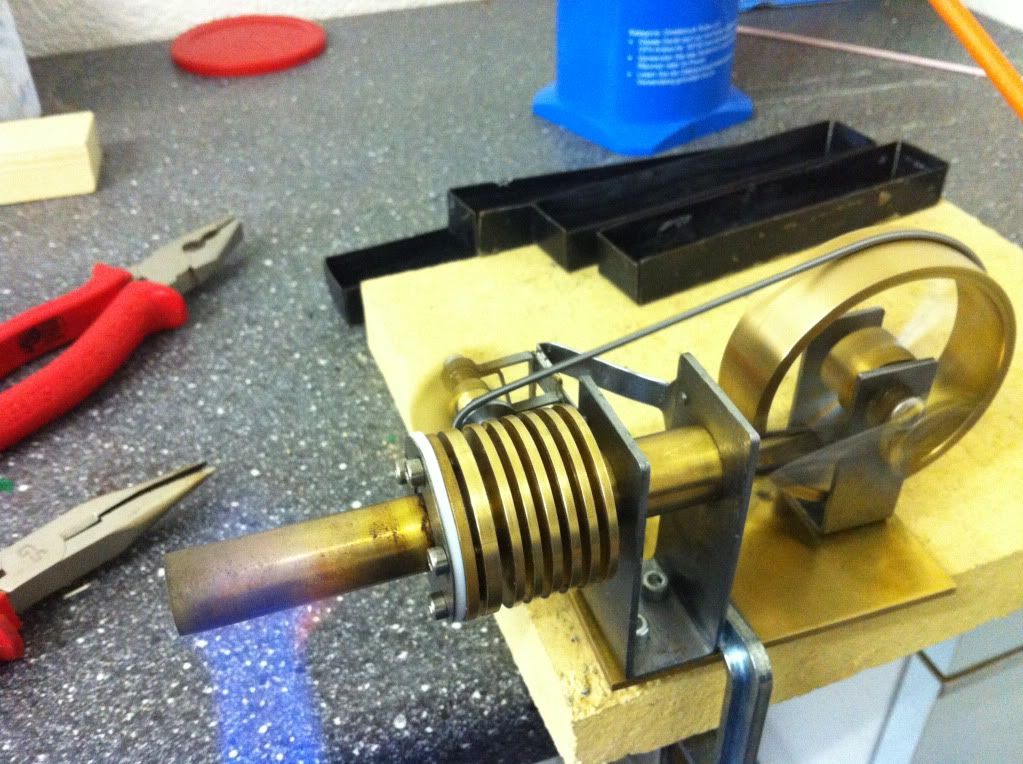
Assemble, fire it up and bingo- we got ourselves a runner!
However the self proclaimed performance upgrade consumes more than it delivers. So there is clearly room for improvement and plans are flying around in my head.
Another huge improvement potential is the overall design, which turned out way more bulky than acceptable at the end. Mental note: get rid of all the bent and soldered sheet metal and make something proper. But at the moment time is rare- so lets see when there will be an update on that one.
Cheers, Karsten
Last edited:
")