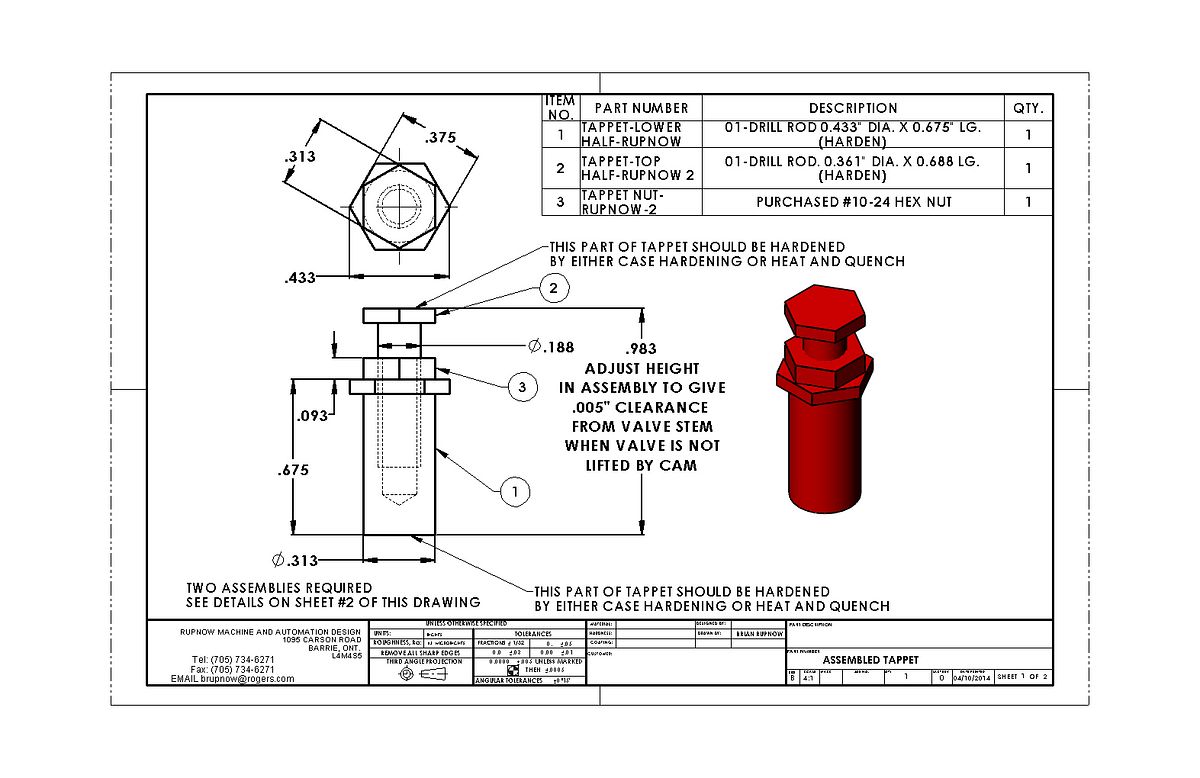
I have had a crazy busy week, and haven't had a chance to play machinist very much. I did come home last night from the factory where I've been consulting for a couple of weeks, and got a good start on the tappets. I figure that if I have to set the rotary table up on the mill to do the cam anyways, I might as well cut the hex shapes on the tappets, which are being made from 1/2" 01 drill-rod. I hope to get the cams done this weekend as well. You are probably right about the shape of the cams not being all that critical. They are very "not critical" if using a follower wheel on the tappet, but for a flat bottomed tappet, if you don't get the curve right on the cam flank, they will 'slap' the bottom of the tappet on every revolution.----At least that's what the books say.-----Brian

You are using an out of date browser. It may not display this or other websites correctly.
You should upgrade or use an alternative browser.
You should upgrade or use an alternative browser.
A new engine for fall---
- Thread starter Brian Rupnow
- Start date


Help Support Home Model Engine Machinist Forum:
This site may earn a commission from merchant affiliate
links, including eBay, Amazon, and others.
Cogsy
Well-Known Member
I'm glad to hear you're back at it Brian - I look for your progress every day and I was beginning to wonder if you'd gotten sick or something.
As far as Chuck's cam cutting method, I used it on my Rupnow build and the cam it produced certainly looked the part, complete with nice curve on the cam flank. I could be wrong, but you may be able to roughly calculate the curve you get depending on the diameter you have your boring head set to cut. The larger you have it set the 'gentler' the curve.
As far as Chuck's cam cutting method, I used it on my Rupnow build and the cam it produced certainly looked the part, complete with nice curve on the cam flank. I could be wrong, but you may be able to roughly calculate the curve you get depending on the diameter you have your boring head set to cut. The larger you have it set the 'gentler' the curve.
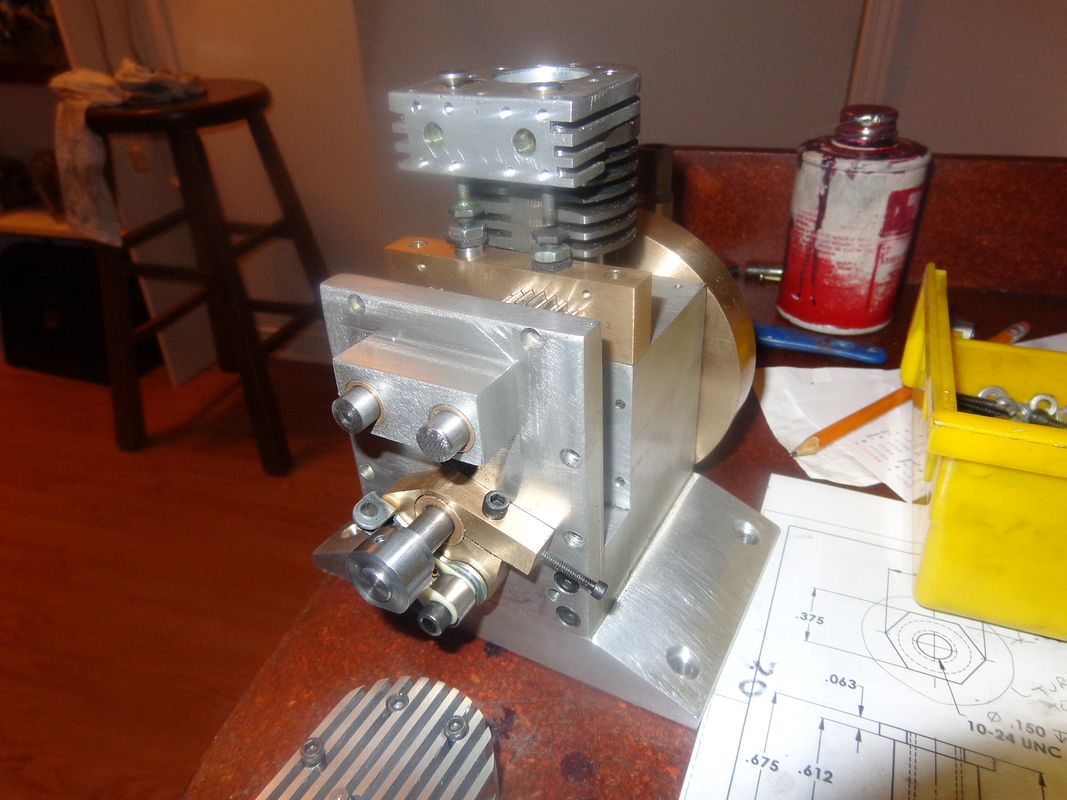
This morning I made the tappets from drill rod, which is a "water hardening steel". The machining went reasonably well, until I realized that I had tapped the wrong end of the larger diameter which rides on the cam!!! After remaking the large ends and getting it right the second time around, I carefully fit everything, then took the pieces out to my big garage for hardening. I heated the pieces one at a time with my oxy acetylene torch until they were bright orange, then tipped them into a can of water. I hoped that I wouldn't get much heat distortion which would have buggered up either the internal or external threads, but I must have lived right this week, because everything went back together fine. The outer diameter of one of the large parts may have grown a little, as it was a tight fit into the bronze guide block and I had to set it up in the lathe and polish it a tiny bit with some 280 grit paper. I decided at the last moment to use mild steel #10-24 locknuts, because it was less work, and I figured when used as a jam nut the mild steel would grip better and not back off while the engine was running. In the picture, one valve is open and one is closed, but the cams are still not made. That will be tomorrows job. The blob of stuff on top of the left hand tappet is some oil I had used when assembling things and then forgot to wipe off before taking the picture.


Last edited:
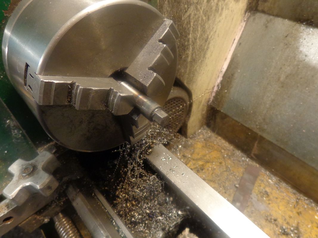
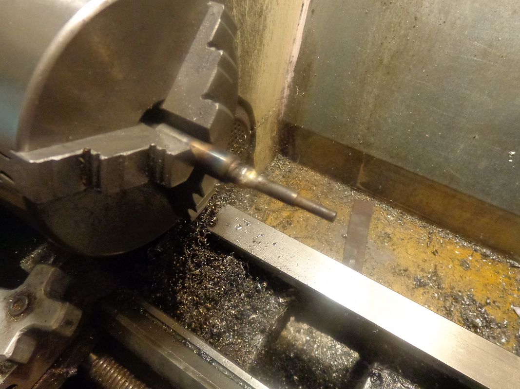
We have a cam!!! Actually, we have two cams, once I get them parted off. Everything went very well, and the profile looks perfect. I took a cut every two degrees of rotation in the rotary table. This leaves only microscopic ridging, which will clean up very easily with a fine diamond file. However, no matter how you do the math, that is 180 trips back and forth with the manual table. My right shoulder will be sore tomorrow from crank turning. Old dogs do learn new tricks---this time after the profile was cut, I left the cam in the rotary table set-up and continued taking cuts every two degrees until I had completed the full 360 degrees. This is an excellent method of making cams, but it is tedious. Tomorrow I will dress things a bit with the fine diamond file and part the cams of from the parent stock. Then they will be flame hardened and quenched, then silver soldered to their individual camshafts.


Okay--Experiment completed. I had a bit of left over 1/2" drill rod. It cuts very easily with a file. I flame hardened and quenched one end, put it in the lathe to hold it, and tried to cut it with a file. Couldn't cut it at all. Harder than the devil's horn!!! I set it up in a vice and silver soldered a small bit of 3/16 mild steel shaft to the end of it, let it air cool, and again set it up in the lathe. The file now once again cuts the drill rod very easily. The heat of silver soldering "unhardens" the hardened drill rod. ---Something worth remembering!!!


Swifty
Well-Known Member
Brian, I was worried about that when you said that you were going to solder on the hardened cams, the hardened part will anneal with the heat. You may be better off using loctite or having a slight redesign where you can have a shoulder on the cam to allow for a set screw.
Paul.
Paul.
Last edited:
AAARRRRGGHHHHH!!!!!!!!!!---Giant headslap for me!!! I cross drilled the cams, hardened the cams, cross drilled the cold rolled camshafts, made up .093" cold rolled cross pins----and trial fitted everything. Was being REALLY careful with the cams. Slathered everything with Loctite, dropped the cam into place, aligned the cross drilled holes, and as I pushed the .093 pin into place by hand, encountered some resistance. Took it out to the anvil and CAREFULLY tapped the pin all the way thru.--And then---just as I thought I had won---I heard a little "crack"!!! OH POOP!!!!!


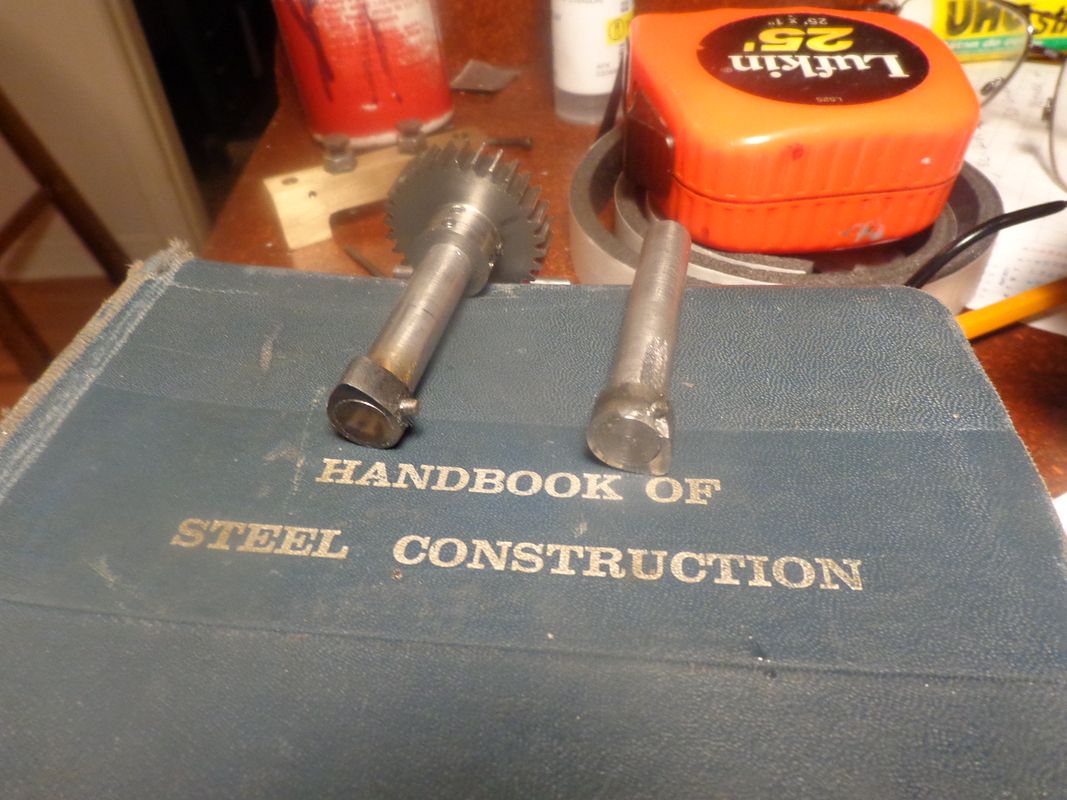
They were supposed to BOTH look like the one on the left----Honest!!! The cross pin is mild steel and will get filed down until the surface is an exact match for the hardened cam surface. And everything is coated with #638 Loctite.

- Joined
- Dec 31, 2010
- Messages
- 783
- Reaction score
- 195
Ahh yes. you've forgotten the other half of the process of hardening steel. The annealing phase (to make it less hard). Clean up the hardened steel nice and bright and then re-heat it slowly until the metal turns straw coloured 200C / 400 F (preferably done in a hot kitchen oven) hold it for 10 minutes or so and then cool it slowly. It won't be so brittle then.
Also another tip for fastening the cams to the gear shafts. If you want accurate valve timing keep in mind that unless you have very fine gears you might find it difficult to get the timing you require by simply indexing the gears a tooth at a time. The gears will have a few degrees rotation between the teeth making it difficult to get exact timing.
You should mesh the gears turn the cams to get the exact timing you want, temporarily hold them in place and then drill and pin them.
Sage
dsage--This whole process of hardening metal is relatively new to me. Although I have known about it in theory from an engineering viewpoint, it is only in the last 5 years since I started building small engines that I have practical experience with it. On one level, I knew that the cams would be glass hard without annealing, and like glass would shatter if overstressed. Knowing it and actually having it happen aren't quite the same. I will remember it now--clearly---until I die. as far as the cam timing is concerned--the gears are not keyed to the shafts. I will have infinite adjustability for cam timing with this design.---Brian.
- Joined
- Dec 31, 2010
- Messages
- 783
- Reaction score
- 195
Good stuff Brian. I figured you had the timing worked out but I wasn't sure how.
Google annealing steel colours (or similar words). Or better yet Machinery's handbook. Lots of information to be found on the various colours / temperatures and what hardness they result in and the typical uses for such hardness. i.e. tools, knife blades etc. Most of the hardest grades can be reached with a kitchen oven. An oven is recommended for even heating and ability to holding the temperature for the required time.
Cams look good. If you have the time, I'd be interested in how the resultant cam agrees with your expected. Set up the cam lobe in your rotary just like you had it when you made it. Use a pad on the end of your dial indicator the same diameter as your lifter. Turn the rotary around to the base circle and place the pad down on a feeler gauge of the lash you expect to use.
Set the dial indicator to zero and the rotary axis to zero. Take some measurements every 5deg or so noting where the cam starts to move the indicator and the maximum lift. Double the degrees (to get crank degrees) and adjust the lift measurements according to your lifter ratio and analyze your results.
I know it doesn't really matter. Almost any cam will work. But I've found it to be an interesting experiment and worth the time to actually understand the cam manufacture vs actual results.
Do both cams once they are indexed to each other for even more understanding. Armed with this info and adjustability you have a test bed for testing engine performance (ease of starting, smoothness of idle, maximum speed etc).
Sage
I have been so overwhelmed with "busy" in the rest of my life, that I haven't had time to devote to this engine lately. I did manage to steal two hours yesterday evening to remake and harden the cam which was broken and assemble the cams, camshaft, gears, and tappets and tappet guide. This engine is getting very close to being a runner. During the rush leading up to having the top end of the engine finished, I forgot to lap the valves into their seats. Fortunately, I can easily access the valve stems to grip them with a finger chuck when the cylinder is removed from the engine, so that shouldn't be a problem. I am very pleased at how well the gear/cam/tappet train seems to work, so have attached a short video of them in operation.
[ame]https://www.youtube.com/watch?v=ZIe3SpxavaA&feature=youtu.be[/ame]

[ame]https://www.youtube.com/watch?v=ZIe3SpxavaA&feature=youtu.be[/ame]
Last edited:
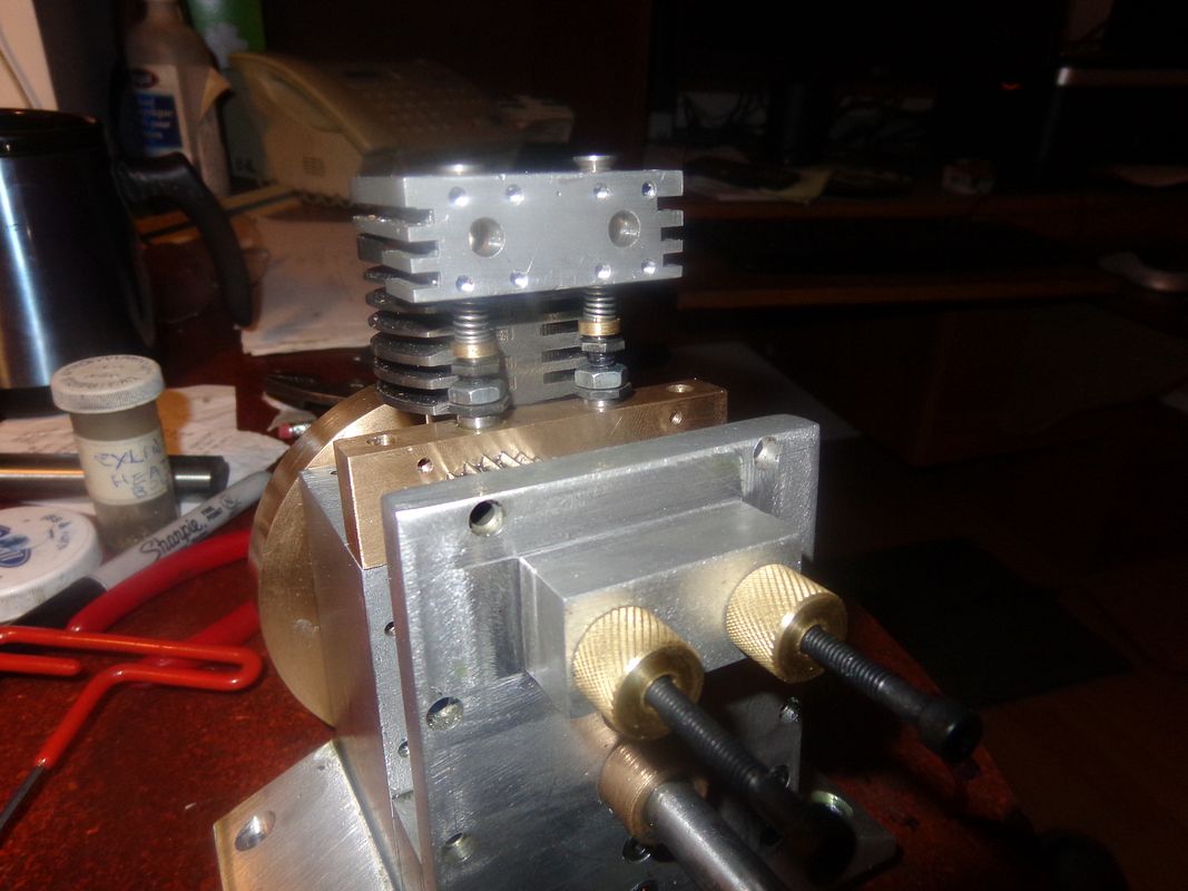
I haven't abandoned ship--Just been very busy. This afternoon I made up the knurled adjuster knobs that fit on the ends of the camshafts, but then found out I was out of #8 socket head capscrews of the correct length. I stuck two in the place that the much shorter ones will go in when I get them. On the right you can see the true meaning of "Make it up as you go." I forgot to lap the valves, and cut the long piece of parent metal off that I generally use for a handle when lapping the valves and seats together. So---I made up a pair of extended 1/4" "handles", counterbored them 1/8" to suit the valve stems, and cross drilled them together with a 1mm (.039") drill for a drive pin to connect them. The valves needed to be cross drilled anyways, so it kills two birds with one stone. I will lap the valves tomorrow and start the final assembly of everything.


- Joined
- Sep 2, 2011
- Messages
- 1,345
- Reaction score
- 360
Looking very good Brian. Sort of late in my reply on the cam but would like to hear more about the heat treat process. I was trying to learn color hardening from"Machine shop projects" but could never understand if after the draw to straw or whatever color if you should quench again or lay it to the side and let it air cool on its on
That said on some knives I found quench after heat treat worked better but still question if that's the right thing or not
Any way your engine is looking good so hears a blue thumbs up👍
That said on some knives I found quench after heat treat worked better but still question if that's the right thing or not
Any way your engine is looking good so hears a blue thumbs up👍
Werowance--I am far from being "expert" on hardening steel, but here is my take. I don't even try to get involved in case hardening because that requires a heat treat oven and I don't have one. I work with either oil-hardening or water hardening steel, commonly sold as "drill rod". My local supplier sells the water hardening type of steel. Both of these "drill rod" type steels are "soft" when you buy them. Of course, "soft" is a relative term. I find then to be a bit harder than common cold rolled steel, but they are still quite machineable with HSS tooling---they don't require any carbide to cut them. I machine to whatever finished shape I want--don't leave any material on for "polishing" after the fact. I heat the pieces with my oxy acetylene torch until they are a bright orange colour--This is hotter than red--hot to the point where if I played the torch on them 2 seconds longer they might start to melt (this is kind of a subjective thing). Then I tip them into a bucket of room temperature water. Thats it!!! They come out of the water harder than glass, and quite brittle. Most of the time, this brittleness doesn't really affect whatever I am using the part for, so I just use them in that state. HOWEVER--I found by experiment that if the hardened parts are then reheated to a temperature high enough to silver solder them, they lose that hardness. I am told by people with more experience than myself that if you can find a way of heating the hardened parts to some mid range heat (I don't know what it is), hold them at that heat for 10 minutes, then let them cool gradually, they will retain most of their hardness but not be so brittle. This process is called "Drawing back". I have never done that part of the hardening process. There--Now you know as much as I do.--Brian
This morning I got up early and lapped both of the valves into the seats. I first lapped them with 400 grit carborundum paste, then after a good cleaning, lapped them again with 600 grit. Everybody seems to do this a different way. In an earlier post you will see the "handles" that I attached to the valve stems. (Normally I leave the parent material from which the valves are cut long enough to be a "handle" and then cut it off after lapping is completed). The valve seat and valve face are coated with the carborundum paste (it doesn't take very much) and then the "handle" is gripped between my thumb and finger and revolved back and forth while pulling the valve into the seat. I do this ten times back and forth, then lift the valve off the seat,rotate it a quarter turn, and then repeat. I do this a total of ten times. Never use a power tool to do this. This is a job for "finger twiddling" only. After a thorough cleaning of both valves and seat areas, the valve springs and brass keepers were installed and the .039" cross pins installed. This as a job that always makes me wish for a third arm and hand, but I manage with the two I have. I am now at the point where I can't really go any further until I can buy a tube of Molycote grease tomorrow for the big end needle bearing. (Do you suppose turkey grease would work?--It's thanksgiving here today.) The valves open and close very nicely, which is always pleasing to see. I hear my wife up now preparing a feast for hoards of children and grand children, so being a firm believer in self preservation I had better get upstairs out of my machine shop and help her.--All you other Canadians following this thread---Happy Thanksgiving!!!---Brian

- Joined
- Dec 31, 2010
- Messages
- 783
- Reaction score
- 195
Brian et. al.
See post 209 and 211 where I explained how to temper steel after hardening.
1. Clean the crud off of it from hardening process so it's bright and shiney
2. Stick the part in your kitchen oven at 400 degF until the part is thoroughly heated (infrared temp meter or thermocouple) and let it bake for at least 10 minutes once the temp is reached. It should turn some sort of yellow-ish colour. Be aware that metal parts take quite a while to heat through. If you have a bright light in your oven you can see the colours change.
3. Let it cool slowly.
As for heating the metal in the hardening process use your torch and heat the part enough for it to become non-magnetic (touch a magnet on it every few seconds - when it doesn't stick any more you're at the right temperature). Don't heat it anywhere near where it's going to melt. Bright orange should do it (subjective of course). Hold the whole part at that temperature for a couple of minutes. These are rough guidelines for small parts only.
RSVP
Sage
dsage--I've only done that once--While my wife was away. Did it to set the temper in some small coil springs I had wound. Wife came home next day and immediately said "What's that smell!!! You weren't cooking something in MY oven were you??---and it all went downhill from there---
Swifty
Well-Known Member
For oil hardening silver steel / drill rod, the specified tempering temperature is 180 - 200 C, (you will have to do your own conversion for deg F), this temperature is easily achieved with a normal kitchen oven, just watch out for the wife.
Paul.
Paul.
Similar threads
- Replies
- 196
- Views
- 17K
- Replies
- 413
- Views
- 43K