A new engine for fall---

Home Model Engine Machinist Forum

Help Support Home Model Engine Machinist Forum:

This site may earn a commission from merchant affiliate links, including eBay, Amazon, and others.
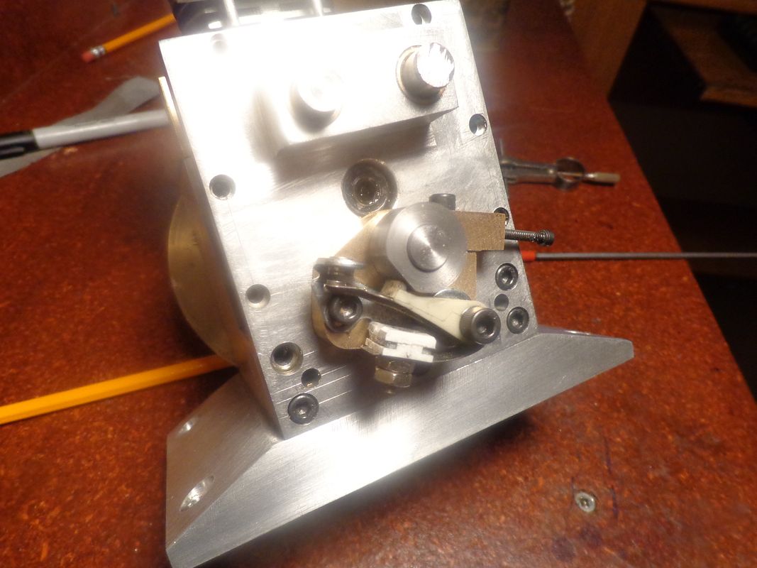
The ignition cam is machined and installed. For any newbees following these posts, this kind of ignition cam holds the points open most of the time. They only close when the flat, which is about 3/8" long pass under the rubbing block on the ignition points. This gives enough time to charge the primary windings on the ignition coil, and when the points open again as the cam revolves, that is when the spark occurs.---Brian
 
This is a piece of high temperature gasket paper from McMaster Carr, 15" square x 1/32" thick. I don't know if you can see the price on the paper laying beside it or not, but it cost me $58.56--That means it is going to have to last me for the rest of my LIFE!!! The gasket only cost $36, but the tax and shipping brought it up to the total price.If I turn the gasket material over, it says Garlock Extreme Temp 9850 on it. The second picture show the temperature sensing laser aimed gun that I bought from Travers Tools. It senses temperature from -4F to 999 degrees F. Right now I don't have anything to test it on except the wall, myself, and various light bulbs. My skin temperature is 92.9 degrees, the wall is 68.2 degrees, one of those curly flourescent bulbs in my office is 108 degrees, a 40 watt incandescent bulb is 135 degrees, and a 60 watt incandescent bulb is 143 degrees.

 
Last edited:
The cast iron cylinder and the aluminum valve body (which I have been mistakenly calling the combustion chamber) are now permanently and forever locked together with a ring of super duper heat resistant gasket material and some high temperature gasket goo.--That's not to say I couldn't take them apart, but I don't want to. I want to treat the two items as a single component now, hone them together, lap them together, and then make my piston to suit the bore.
 
Not much machining accomplished today. I'm a bit overwhelmed by 'real' work right now, plus making a wooden cabinet to hide an ugly wall mounted 100 amp electrical service at my son's house. I did manage to steal 20 minutes out of the day to hone the cylinder/valve chamber with my 3 stone brake hone, and to lap it using a piece of 1" aluminum round bar and first #400, then #600 carborundum paste. Sometime in the next few days, I will use the other end of the 1" aluminum round stock which is not polluted with embedded carborundum paste to make a piston. Good Heavens!!! If I get a piston made, then I am getting awfully close to a finished engine. Oh yeah, I forgot---I still have tappets to make.---Brian
 
Now in Fukuoka,Japan----a not so crowded city. Though not speaking a word of Japanese, I can move around by underground train.
Take it easy. Most of us have the same problem with the last item to make amd complete engine.
Might to revive the nearly lost art of making WW-1 and WW-2 copper cladded outerhead gasket. I can still still buy asbestos gasket here in Singapore below the counter.
Will track your engine post here in Japan. Take care.
 
I haven't had a very "machiney" week due to other obligations. I hope to make a piston sometime today, and I have realized that due to adding the 1/32" gasket between the valve chamber and the cylinder body, I will have to make the piston 1/32" taller between the gudgeon pin and the top surface, in order for it to come even with top of the "deck" when at top dead center.
 
Hey Hey!!! we got a piston!!! That's two things accomplished today. Machined a piston and got a haircut. Damn, I'm a good looking fellow when I get a haircut.--Look just like Elvis---sorta---
 
I'm very pleased to announce that with rod and piston installed and all gaskets in place, the crankshaft does indeed go "round and round". No matter how much fancy 3D cad modelling I do and how many calculations I make, this is always the moment of truth for me. I actually had one little heart stopper---the crankshaft wouldn't make a full 360 degree rotation when I first assembled everything. I took out the bolts that hold the cylinder to the crankcase one by one, but it wasn't that. Then I pulled the head off----and discovered that the top of the piston actually comes up about .013" higher than the top of the deck. That would have been okay, I have .060" clearance milled into the head.---But--I had cut the gasket hole a bit small, and the piston was hanging up on the gasket material. A bit of very careful exacto knife work to trim the gasket, and that fixed things. A big sigh of relief----Brian
 
Jeez, we're really coming down to the wire here folks.The two knurled items in this post will be what allows me to grip the ends of the camshafts and rotate them by hand after loosening of the set-screws in the timing gears to adjust the cam timing. They also limit the axial movement of the camshafts in their bushings. They will be bolted and Loctited to the ends of the camshafts.
 
These are the parts I've been saving until last, for two reasons. First reason is that 95% of the engine has to be built before their is a place for them to go, and the second reason (the real reason) is that I'm not sure how I am going to make them. The method outlined by Malcolm Stride in his Bobcat/jaguar/Lynx series works very well, but involves an awful lot of mill cranking. The second method which I believe Chuck Fellows made a video of and involves doing them in a rotary table on the mil looks a lot simpler, but I'm not certain about being able to hold the accuracy with the Chuck Fellows method.
 
So--What did I do wrong? I just used the cam-calc program http://modelenginenews.org/design/CamTable.html to create this cam profile. My inputs were --cam angle=120 degrees--valve lift 0.080"--flank radius =.640" --base radius =0.240" --engine rpm 3000, and 2 degree angular increments. It created a profile that dishes in rather than out like it is supposed to be. I am not sure I have laid it out correctly but I think I have.
 
And just for interests sake, that generates a nose radius of a whopping great .1815" . I'm sure I must be doing something wrong. Maybe the calculator doesn't like such a slow engine speed. The only really major difference between the inputs for this cam and the one Malcolm Stride generated for his Bobcat and Jaguar engines was that he used an engine speed of 5000 rpm for his inputs, and his cam profile turned out like one would expect a cam to look like.
 
I must be doing something wrong in my layout. I just reran the cam-calc program using a 5000 rpm input and it spit out exactly the same numbers as for a 3000 rpm input. The output for both 3000 rpm and 5000 rpm inputs is also telling me that the nose radius will be .080" which I expected it to be. I'm doing something wrong in my layout. I just have to figure out what it is.
 
Okay--I'm sorted out. I have figured out that my layout was incorrect. I am currently working on a 3D cad model which will give me the proper profile when finished, but it's not quick nor easy. I have to create a solid, then rotate it and machine away portions of it exactly as I would in the machining process. I will post the profile when I get it finished.---Brian
 
<edit>. I see you have it sorted out but perhaps you can comment on my notes below - to refresh my memory and to help others use CamCalc.

Hi Brian:

The RPM value in CamCalc has no effect on the profile (as you found out) except that you can analyze the dynamics of the finished cam from a table of acceleration per degree of rotation etc. I'm not sure where that table of results is output so it's a moot point.
I can't run Camcalc here on Win8. It generates a security error of some sort that I can't get past.
In any case. What are your assumptions about the numbers that CamCalc puts out?
From my feeble memory, I believe the numbers are depth of cut figures. The smallest numbers (nearing zero) are for the nose of the cam and the depth of cut numbers get larger as you progress around the cam. Zero degrees being the nose of the cam and 180 being the largest depth of cut and across from the nose. I believe it also only outputs number for 180 deg of rotation and you have to repeat the numbers in the reverse order for the other half of the lobe.
I also seem to remember you have to do some subtraction for every angular step to get the number to actually work with. But I could be wrong. I haven't used it in a long while but I believe this is the case. See if that line of thinking helps. Hopefully I haven't steered you wrong.

Sage

This would be a fine place to put in a plug for my Gcam program used to grind cams for those equipped with a CNC mill. But I digress.
 
PS>

Brian:
I believe CamCalc also outputs a minimum lifter diameter. Be sure to heed this minimum and even add a bit to it else the edge of your lifter will dig into the cam. as it rotates. This lifter diameter will then need to be checked for clearance in your engine.

Sage
 
This was a battle royal, but I got it sussed out. The end result is happy!!! The cam profile generated by using all of the inputs for machining from CamCalc is a VERY VERY close match to what I had originally designed. I feel confident that if I use the generated numbers when actually machining my cams, I will end up with the result I was after.
 
dsage--Thank you for your interest and input. Camcalc calls for a minimum lifter diameter of .296", and my tappets are going to be 0.3125" diameter.---And that was more good luck than good management.
 
Hi Brian, The little beast is looking good. Glad to see you got the cams sorted out. For what it’s worth I used the method Chuck shows in that video when I did the cam on my Webster and it went pretty fast and easy.
 

Latest posts

Back
Top