A new engine for fall---

Home Model Engine Machinist Forum

Help Support Home Model Engine Machinist Forum:

This site may earn a commission from merchant affiliate links, including eBay, Amazon, and others.
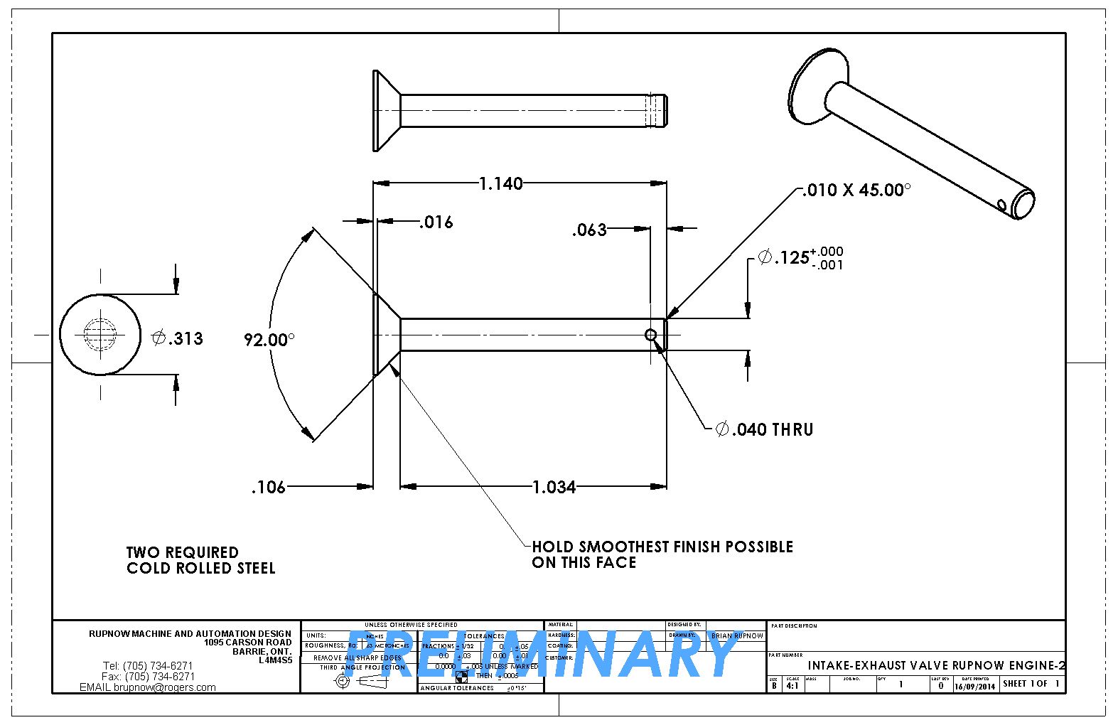
Sometime to day I hope to visit one of my suppliers and pick up some suitable head gasket material and some high temp sealing compound for the two bolts that have their heads exposed in the combustion chamber. I don't want to hone/lap the cylinder until after I have permanently locked the cast iron cylinder and the valve body (which I have been mistakenly been referring too as the "combustion chamber") together. In the meantime, I have just rattled off a quick detail of the valve. I see some people make valves out of stainless steel and other exotic materials, however I have always used just plain old garden variety cold rolled steel and never has a valve fail.
 
And in case you are a bit confused about how this valve business goes together, here is a cross section thru the valves, cages, tappets, cams, etcetera.
 
Oh Heck--While I'm setting here waiting for a call back about gasket material, I may as well put up a drawing of the valve keeper.
 
Last edited:
We have valves and valve keepers!!! I had to order some gasket material and some extreme high temperature sealant and it won't be in until tomorrow, so in the interest of keeping things moving, I machined the valves and the keepers today. The valve on the right is open .080" which is the rise on the cam shaft, and the valve on the left is completely closed. Unlike an automobile engine, these valves set up a bit from the flat surface, even when they are closed.
 
Last edited:
If you guys remember back to when I made the crankshaft, there is a .563" diameter spacer ring on the back side of the web on each half of the crankshaft. This web is in there to maintain some clearance between the revolving crank web and the inside of the crankcase, as well as to locate the crankshaft so it doesn't float back and forth in the crankcase as the engine is running, making a clatter. Due to accumulated tolerances when machining, the thickness of this spacer ring invariably ends up either too thick or too thin. I have made it a separate piece Loctited into place on the crankshaft and here is why. Since my crankshaft is a two piece and comes apart in the center, I can make up this "setting master" fixture, insert the large end into the cylinder, and let the small end hang down into the crankcase and put the crankshaft "throw" through the 3/8" reamed hole. The small end at 0.531" is exactly the width I want between the webs of the crankshafts. Then a bit of careful measuring done by sliding each end of the crankshaft to its extreme travel in both directions should let me know exactly how thick these spacer rings should be made.

 
Here is a picture of the Setting Tool in place. The cylinder fits over it and locates into the counterbore in top of the crankcase. I have made it and installed it and the results are about what I expected. Although the design calls for a 1/16" thick spacer on each side of the crankshaft to prevent endplay, in reality there is virtually no endplay in the driving side of the crankshaft, but it is still free to rotate. The other end of the crankshaft, the "follower" end will require a 1/32" spacer. Why the big difference from the design.--Well, mainly because of "stack up" of tolerances. There are a lot of pieces fitting together to give this theoretical 1/16" spacer on each side. Although I could have held all of my tolerances much closer when machining the parts, I doubt that I could ever had everything come out as a perfect match for the drawing. The 0.531" wide setting master will allow for a 1/2" wide connecting rod and a 1/64" brass or teflon spacer on each side of it between the webs.
 
Today I'm just tidying up loose ends, so decided to machine the starter collar. This bolts onto the brass flywheel and lets me use my variable speed drill as a starter.
 
So now the engine has a starter ring. If I ever get finished to the point where I want to start it, the ring will be waiting for me.---On to more interesting things like pistons tomorrow. (I hope!!)
 
Somebody messed up, and my gasket material never got ordered. Now it's ordered and won't be here until Monday or Tuesday. This doesn't cause a huge problem, because I'm up to my armpits in "real" work right now and have no time to play machinist. This drawing is an interesting part. I have made it before. It mounts a set of my favorite Chrysler product ignition points, and clamps onto the extended head of a crankshaft support bushing. By loosening off the clamp bolt, I can manually adjust the ignition timing while the engine is running. This is no big thing once the engine is all set up and running at its optimum timing, but it sure is a nice thing to have when first starting the engine and "setting up". I used this when I built the Odds and Ends hit and miss engine designed by Philip Duclos, and it really is a handy thing to have on the engine.
 
Now I have enough work to keep me going until the gasket material arrives. There is a big chain of consequence attached to the lack of gasket material. I can not permanently attach what I have been calling the "combustion chamber" to the cast iron cylinder until I have a ring of gasket material to insert between them to prevent loss of compression. I can't hone nor lap the cylinder/combustion chamber until they are permanently attached to each other. I can't make the piston until I am finished the lapping and honing. I'm sure there will be enough work in this con rod and the points mounting bracket to keep me going until the gasket arrives next week.
 
Plan to build this engine 2015. Too many lazy bones in Gus and meanwhile doing other min projects and will
run Nemett-Lynx Engine when I get back from the 43rd Japan Honey Moon with my ''better half''.

This engine will be require some new skills and old skills upgraded.

Looks like Gus is building one engine p.a. Five years from now I have ten engines.
 
Gus--Glad to see that you looked in and said Hi. I was wondering where you've been!!! I hope you live in good health until you are 100 years old. It will take that long to build all the engines that you like.---Brian
 
Here we have the con-rod layout. I don't work to the layout lines, but they let me know if I have turned the dials on my mill one too many times when I am actually machining it. I don't trust my mill vice to hold this perfectly flat while working on it. I will put a sacrificial plate underneath it and use hold down bolts in the tee slots to hold it flat on my mill table while drilling and boring all the holes. Two critical holes for the bearings at each end which will have to be bored, and 4 drilled holes to form the radii where the straight sides blend into the round ends.
 
Now I know what I DON'T want to be when I grow up!!!---A cooling fin slot cutter!! The .093" slitting saw works amazingly well, but at 0.100" depth of cut, thats 4 passes per fin-slot x 11 slots = One heck of a lot of cranking on a manual mill. The sparkplug is a 1/4"-32 Rimfire plug from Roy Sholl. I didn't get too crazy finishing the bit of combustion chamber inside the head. It will work just as well the way I have it as it would polished.--In fact, it might work even better. I am really pleased with the way the engine is looking.---Brian

Hi Brian finally getting a chance to catch up here. I remember reading in an Edgar Westbury article (might have been on the Whippet) that with side valve engine you want turbulence in the top of the head to promote better air fuel mixing. So you’re right and it is better than if it was polished.
 
Engine is looking fantastic as usual Brian (maybe better than usual even).


I will put a sacrificial plate underneath it and use hold down bolts in the tee slots to hold it flat on my mill table while drilling and boring all the holes. http://s307.photobucket.com/user/Br...upnow016/CONRODLAYOUT004_zps7db3bc96.jpg.html


I'm curious, do you flatten the sacrificial plate at all before you use it? I ask because I will need to use a plate like this shortly and I'm wondering if the flatness of purchased plate is 'good enough' or I need to prep my scrap before I destroy it.
 
That went well!! The machining was pretty straightforward stuff. I did learn one new thing today. When you order this type of bearing, the outer diameter comes in at .0005" to .001" oversize so that they can be pressed into a hole made by a standard reamer. For 49 years now I have been putting a note on machining drawings "Bore for light press fit of .562" nominal o.d. bearing (or bushing).--I never actually realized that there wasn't some magic formulae or set of undersized reamers involved to do this. As you can see in the picture, the 1/4"small end bearing is sealed with rubber seal lips. I was unable to buy a sealed 3/8" i.d. needle bearing----anywhere, for the big end. I guess this means that I will be running some oil in the crankcase after all.
 
Last edited:
bmac---As an old hot-rodder, I am well aquainted with the practice of "porting and polishing" the intake runners on flathead ford engines to give the engine more speed. Then in the 1980's Hotrod Magazine published an article showing that based on dynamometer tests, polishing the intake runners was actually detrimental to the engines performance. It seems that the rough cast surface of the intake runners created turbulence in the airflow, keeping the droplets of gasoline (it isn't really a vapour) suspended in the airflow, far better than a polished surface did, thus giving better engine performance.---Brian
 
By Golly, Miss Molly---I must be doing something right!!! Along with all the other things I had to do this weekend, I managed to carve out enough time to make the con rod AND the ignition points mounting block. I decided at the last minute not to put the raised boss on that is shown on the drawing. The head of the bushing it clamps to only extends 3/8" past the aluminum backplate, so that is the thickness I finished the points mounting block at. I used a scrap of bronze, just to balance the bronze flywheel aesthetically. The points mount up perfectly, and all it need there now is an ignition cam to finish that bit off. The #5 capscrew sticking out horizontally is where the handle will screw into, to adjust the timing.

 
Time for one last "Quicky" before I shut down for the day. The all important ignition cam. This cam serves a dual role in life. It opens/closes the ignition points, but also acts as a shaft collar to prevent any axial movement of the driven crankshaft in its bushings.
 
Back
Top