3D Drafting and Design Software Comparison

Home Model Engine Machinist Forum

Help Support Home Model Engine Machinist Forum:

This site may earn a commission from merchant affiliate links, including eBay, Amazon, and others.
Hey, just to backup my pervious comment about price, I did a google search for educational prices of gold standard 3d parametric modeling software. What I found is Solidworks Student Edition cost $140; Inventor Student Edition is $205. Thats not too far out of reach for most.
 
For me there would still be the learning curve. Plus, I am not a student.....and if you are a student what does support cost?
 

Good point about not being a student. Some would be ok with just knowing a student.

Anyway, I look at the learning curve much like I looked at it when starting this hobby. Any day I learned something new was a good day. There is a learning curve to these programs. W/O help it might be pretty steep. I know though a couple of hours with an Invertor user would give one a pretty good start.
 
G'day Pat J,
I too use Alibre, I purchased the personal edition for $120.00 AUS.
I am way too tight fisted to spend $3000.00 for the 4 axis cam plug in so I bought Meshcam for $180.00. I can draw in Alibre 3D then export the file as a STL format then import into Meshcam for 3D post processing, Including 4th axis rotary table function. The only down side is you can not do continuous rotary machining but with a bit of planning I can find a solution most of the time. I reckon both packages work well together and it all came for under $500.00. Alibre is quite easy to learn and the support network is quite good.

Barry.
 
I started out on the 'board' with the Ford Motor Co. I was a pattern designer for the casting division. We created large linen master drawings, they were 42" tall and the lengths could be up to 8' at times. I worked with fellows who had a great understanding of drafting, projection and just plain visualization of three dimensional parts.
After making drawings with pencils, and mechanical protractor heads along came our first introduction to the electronic world. I believe the program we used was Computervision. They weren't doing very well and Ford funded them by using their product exclusively.
When these programs first came out parts had to be created with projected solids or patched with surfaces. No one was into parametrics at that time.
Working with the casting division everything we drew had fillets or radii on the corners. These early programs didn't like filleting at all, sometimes they worked and sometimes they didn't.
Years passed, software came and went, things got better and way more expensive. To purchase what was known as a 'seat' or one license cost thousands of dollars.
After that brief resume I'll get to my point.
For the home modeler who doesn't have access to CNC why do you need a solid modeling program. In some cases the learning curve is steep and in others without proper schooling you might as well forget it.
I don't mean to step on anyone's toes who uses it but just to have it to see if mating parts might interfere isn't worth the time it takes to learn it.
In this hobby most of the people can operate a mill and lathe. These are necessities. From this point a few branch out to CNC, pouring their own castings, EDM work, anodizing and quite a few others. Wherever your interests take you and you can afford it by all means give it a try.
Having come up designing parts with basic tools I use a good 2D program to do all of my work. Yes I have a 3D program but I only 'play' with it as part of my hobby.
To do any kind of design work a person needs a very good understanding of what a part looks like in modeling space and how that equates to putting it on paper or in this case on a computer screen.
The lead in to this thread asked the question about software comparisons. I have another question. What do you need it for?
As I stated earlier, I don't mean to ruffle any feathers, but it seems like people are looking for something they don't really need.
gbritnell
 
George makes a good point.

Just knowing how to "drive" the code won't design a quality engine or part.

We must invest in our own education to do that.

Dave
 
George,
I do not really disagree with you, I spend most of my time drafting with 2D. This is partly because I work with original Lima Locomotive Works drawings and they are all 2D and made a full size engine.

The one use of 3D that I use is to get patterns printed or metal parts printed. The learning curve is step but for some cases it is worth it in my opinion.

Dan
 
Hi Dan,
I totally agree with you. It's a wonderful tool if you have a use for it, most of us don't. If a person understands 2D drawings they can design and draw what they need and it will get them by quite well. I have a bunch of 3D models that I have created. They just sit in a folder and every once in awhile I open them and say "boy those are really cool". Then I put them back to bed. I don't know whether this will open or not but I'm attaching the model I just made of my V-twin crankcase, gear side. It keeps me sharp with modeling but I have no further use for it.
George

View attachment V-twin ccase master cam model.doc
 
I don't think MC9 is quite at the modeling level to which the thread speaks. Programs being addressed are considered parametric and can create assemblies and moving simulations with constraints and flexable joints. MasterCam can import solid models from these programs and generate some nice tool paths for your CNC but I'm not sure its billed as a top tier solid modeling program.
 
Jim,
I think you missed my point here. No matter what the 3D modeling program is, what is the home engine builder going to do with it. Most of the fellows that use it come from a background of using it on their job. If a person wants to learn it more power to them but after they've gone through the learning curve and built a simple model, then what?
George
 
George,

As a 2D man I agree with you. The thing is I have Turbocad 12 professional and there is all this stuff about lofting and extruding etc. I have had a crack at 3D using TC12 but as yet I can't get my head around it with any real success.

For me the bottom line is "I want to understand it." rather than I need to understand it. The 3rd axis appears to have no logic in the scheme of things but I'm sure that's me, not the program. Any expansion of knowledge is usually a good thing. From drawing board to 2D CAD lifted me from a poor drawer to being able to share an idea across the planet and have a better than even chance of the person at the other end being able to decipher my intent. I think 3D, (when I get the hang of it), would increase my chances even further.

Best Regards
Bob

 
I bought several versions of TurboCad and got pretty good using it in 2D mode. I use it to create layouts that are then run through Sheetcam to generate Gcode for my CNC machine. For this it is great.

I tried several times to understand its 3D ability and it drove me pure nuts. I eventually got Alibre and got into 3D very quick and easy.

I really believe Alibre as a solid modeler is a great benefit to a home shop guy. The ability to design parts, see accurate renderings form any view, test fits and clearances, is very helpful.

I cannot even imagine trying to do a design as complicated as Georges Vtwin in a 2D CAD system. Id call that cruel and unusual punishment.
 
I agree Alibe is a great tool the home guy that wants to design an an engine a machine or whatever very powerfull not teribly difficult to learn and not overly expensive. for the hobby version.
Tin
 
SolidWorks is definately the way to go. I had 4-years of board drafting until I was introduced to 2D Autocad in 1996. I used Autocad for about 5-years after that until the company I was working for switched to SolidWorks. I hated every minute of it and it was not an easy transition....for about 3-weeks. Once you build your first assembly and make changes, you will then see how powerful the program is. You really have to use it to appreciate it. Since then I have used Pro-E, SolidWorks, Inventor, and Alibre but SolidWorks still takes the cake (for me anyway).

If you navigate to the "Help" section in SolidWorks, there is a 2D to 3D transition page that helps the big move to 3D. It explains the differences between "o-snaps and constraints" and so on.

I have at least 2-dozen steam engines in SolidWorks and they "run" great on screen.

Chris
 
At last,

My present has arrived.

3Dcad.jpg


Right now I don't know if my workplane is by world by facet or by entity............. In fact I feel a none entity.

My world co-ordinates are out of this world

My user co-ordinates are more abused than used

My entity co-ordinates are in a similar fix to my workplane.

And to think I'm doing this for fun. ;D

Best Regards
Bob
 
Pat J,

Thanks for the support. :bow:

At this stage I have no desire to extrude anything although the DVD is a candidate for lofting. ::)

Best Regards
bob
 
Pat J said:
Screenshot No.14 is a new part, which is a rectangle that was extruded, and then two holes where drawn in the top plane and Extruded Cut through the piece.

Perfect example of a common piece of steel with 2 holes drilled in it
in latter examples you use your design tables those holes can change dia or location without affecting the base part

Screenshot No.15 is a new part, where I selected Extrude Boss, and then at the same time drew a rectangle and a slot, and then extruded both. That was a bit of a surprise because instead of extruding the slot out as it did with the rectangle, it extruded cut the slot into the piece. Two steps using one 2D sketch and one extrude command.

Perfect example of a bounding box pricniple there is an outer surface and inner surface so in autocad parlance boundry box hatching
One off part fast draw ready for assembly


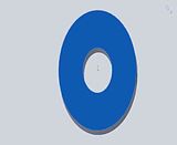
For Screenshot No.16, I drew 3 circles on the top plane, and then did an Extrude Boss/Base command. I was prompted to select which objects to extrude, so I selected the inner circle, and the outer circle. So looking at Screenshot No. 16, did I draw one part or two?

One item only (yep know you know how young enginers can design stuff that noboddy can make ;D

Get back to some more questions latter mate keep em coming this is fun you ask the best questions with perfect pictures

(continued)
 
I use Unigraphics NX at work it's way to spendy to get personal copies but they did mention they were going to offer a student license. Del Cam offers a free package I have not tried it as I can use NX and have used it since I graduated way back from the T square and board. :big:
DelCam
 
Pat,

I just looked through all of the screen shots. Let me put some screen shots of my own together of me building a piston, crankshaft, and an eccentric for starters. There are a few golden rules of 3D CAD that I would like to share with you. As for assemblies, yes you can build each part separate and then build an assembly from your parts. You can also create parts "on the fly" in an assembly but that can get confusing, especially for a beginner.

Give me some time and I will post some screen shots.

Chris
 
O.K. Pat.....instead of screen shots I took video screen captures of me creating a crank disc, crank pin, and then assembling both parts together. I also downloaded a 4-40 set screw from McMaster Carr. Almost everything they sell is available as a SolidWorks CAD model.

I hope you can view them....and I hope they help.

One major thing to remember is your sketch relations. I go over sketch relations with my students for two classes before they extrude anything. Sketch relations govern your sketch geometry. Without them you would have lines, arcs, and circles just floating around. Dimensions are the simplest form of sketch relations, they govern the size of the geometry. A "vertical" relation added to a "line" is telling SolidWorks that the line you just created is a vertical line...not a horizontal line or a diagonal line. Try and familiarize yourself with the sketch relations, they are the key to any good and more importantly "stable" CAD model.

Also, if you see "blue" geometry in your sketch..this means the sketch is "under-defined" and it is missing a sketch relation or a dimension. You want your sketch geometry to have solid black entities. Another indication that you are missing a relation is a negative sign to the left of your sketch located in the feature manager design tree. Usually located on the left side of the screen.


Good luck.

Chris
 

Latest posts

Back
Top