1/4 scale blown v8 build

Home Model Engine Machinist Forum

Help Support Home Model Engine Machinist Forum:

This site may earn a commission from merchant affiliate links, including eBay, Amazon, and others.

rcfreak177

Well-Known Member
Joined
Mar 18, 2010
Messages
324
Reaction score
68
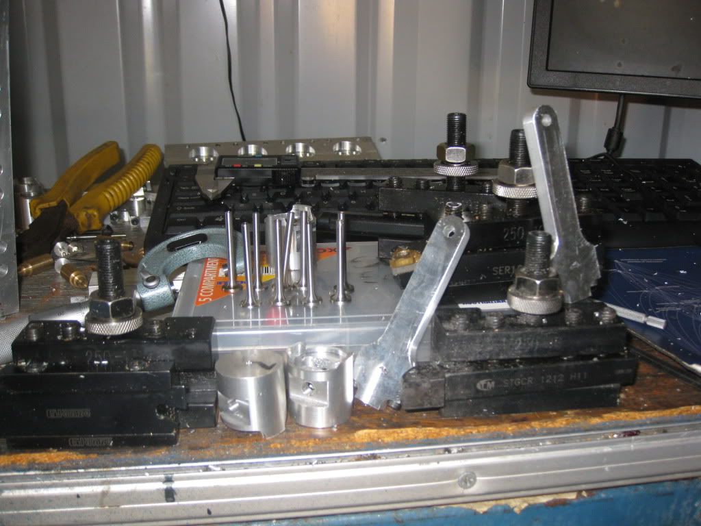
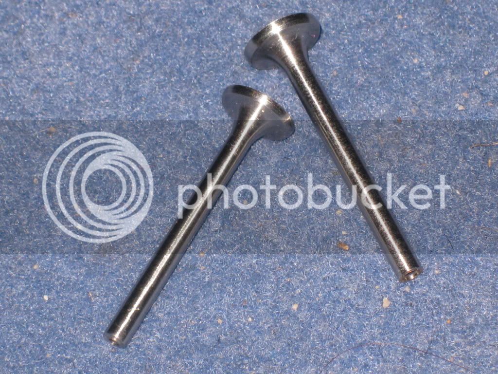
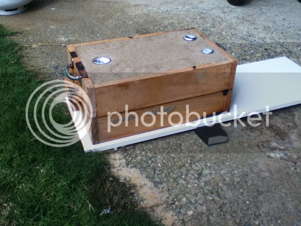
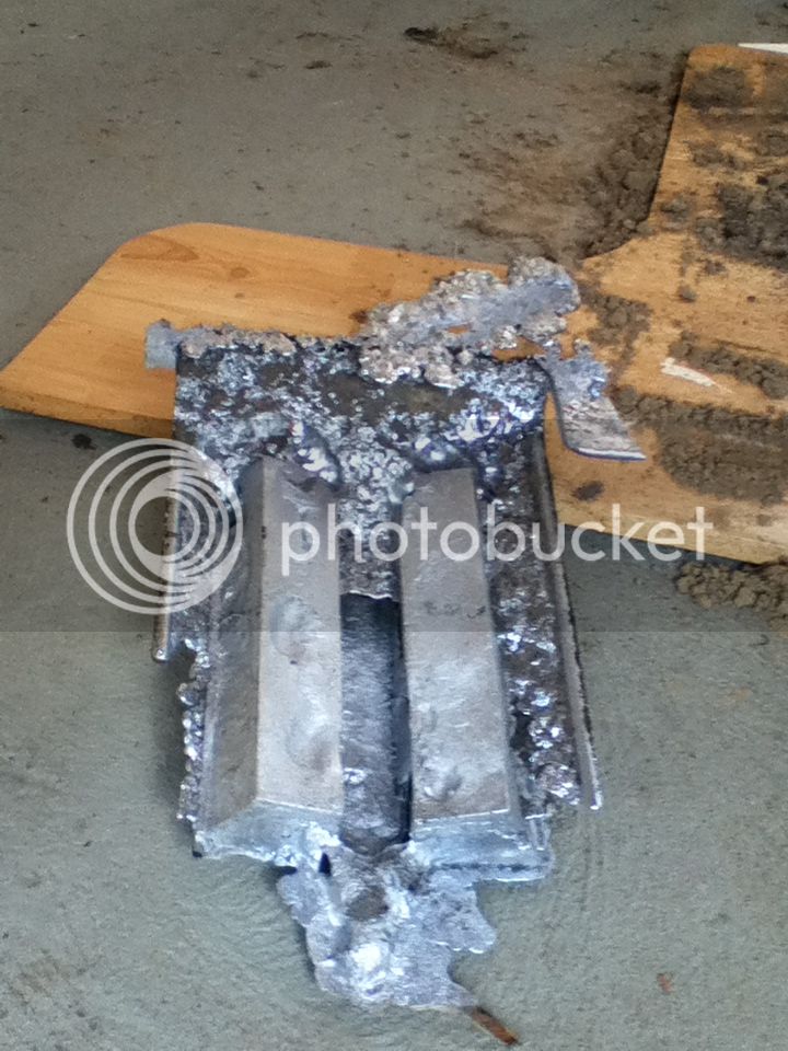
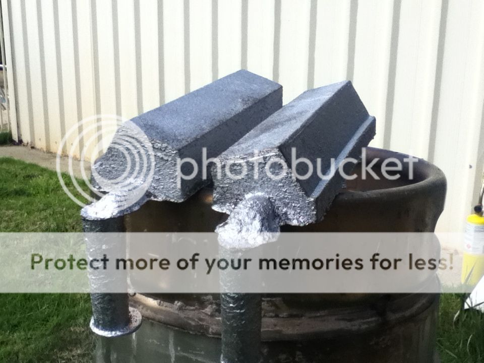
Here are some pictures of the mini v8 I am building. I am having real progress on the at the moment, today I finished the combustion chambers and the valve porting. I am machining the heads in 3 major steps, milled from 75mm dia billet in my 4" cnc rotary table to +1.5mm all round, then mill to +.25mm all round and mill combustion chambers and valve bores and finish all drilling and tapping etc, then finally to size on all major surfaces for appearance, The 6061 ali machines well leaving a great finish when machined with inserted tools running fast. The project is gong to take the good part of 12 months but I will keep posting cool pictures as I go. I machined the combustion chambers with a 1/8 ball nose cutter and it left a few small ridges and am not sure if this will affect the combustion process. I still might clean them out prior to final assembly.

http://s897.photobucket.com/albums/ac174/rcfreak177/machine shop pics/
 
Wow, that's some right purty work. Nice set of machines, too! Is this your own design or are you building from someone else's plans?

Chuck
 
That does look very nice, and I'm looking forward to seeing your progress. Can I ask where you like to get your 6061 and other materials in Perth?
 
I think it's great work. :bow:

Best Regards
Bob
 
Hello All, the supplier I use for 6061 ali in Perth is Bohler in Canningvale, the range is limited to 6" dia also any 7075 I need had been purchased from ebay. I do need some 7" dia 6061 2xpc by 8" long if anybody knows where to get it from, (engine block)

I am working from a set of plans that i also purchased from ebay. I think that they are for the Devcchio foundry castings but they do not have all the detail to manufacture from scratch, I have had to fill in the gaps by drawing on autocad for some of the measurements.

Thanks for the compliments, I have spent hours browsing this website and found great inspiration here, the knowledge and support from other members is unreal.

I would like to make a nitro powered 1/2 scale v twin Harley Davidson Evolution engine in the future, first things first V8 on the mind 24/7.
 
Hello all,

I have updated my pictures of my v8 build, I now have drilled the bolt pattern and clearance holes for the push rods in the cyl heads, I also have roughed out 8x conrods and manufactured the valve guides/seats from brass. I also have made a start on the pistons which need to be finished milled and then finished turned on a jig that I have made. the pistons are machined back to back and then parted off in my lathe.
The conrods now need to be split with a slitting saw in my mill, drilled and taped bolted together and then finish bored, I still have a long way to go but i have progressed dramatically. I must admit the cnc conversions I have done on the mill and lathe are proving to be a sure thing. Once I have finished the parts on the go now I will start on the block, piston liners and valves. I have found I can run the mill and the lathe simultaneously by borrowing the computer from inside the house, much to my wifes disgust, "oh no she can't spend all day on facebook" what a shame HA HA HA!.


http://s897.photobucket.com/albums/ac174/rcfreak177/machine shop pics/


It's good to see your progress, RCF. It won't take 12 months at this rate.

What are you using for pistons, rings and liners? Thanks very much for the Perth supplier information too.
 
G'day Tk,
The pistons are manufactured from 6061 aluminium, the liners and rings will be manufactured from either 2p or 3d cast iron, still deciding. The rings will have to be heat treated and then annealed to get the required hardness but also remove some of the brittleness. Yes you are right at this rate I will be finished in a few months. Thanks to Rio Tinto I was rendered unemployed 3 weeks ago from a mine site which I worked on north of Newman W.A., I have been flat out in the shed making parts, The money has nearly run out so I will have to find a job. It is fairly quiet out there at the moment in Perth and I don't want to do the fly in fly out gig anymore as my children are getting older now (12 and 7) lucky I have my family and hobbies which always keep me smiling
I will post some more pictures over the next couple of days. I am interested in the scorpion V8 you mentioned, is it a water cooled spark plug 4 cycle design?
I searched the web and can"t seem to find any info or specs on this engine.
please elaborate I am curious. ???
 
information for the scorpion v8 refer to sic magazine to which is available direct strictly i c or try plough books in victoria .

its a glow engine quad cam setup
 
Hi RCF
Sorry to hear about Rio - that must be really harsh. I considered FIFO a while back, but also came to the conclusion that it would be too disrtuptive to family life.

Thanks again for the information on the metals you might use. I'm picking your brains (and the other kind folk on this forum) because I intend to build a V8 as soon as I get a bunch of other unfinished (non-engineering) projects out of the way. I don't have much (any recent) machining esperience, so it will be a slow learniferous process.

While I have the Scorpion plans from SIC (buried in a box somewhere at the moment) I'm not going to build it verbatim - I don't think anyone but the author has built a running one yet. It was designed to go into a model boat. Here is some info from Plough books:
Scorpion V-8 designed by John V. Thompson. A 1/4 Scale Original Design Engine, 4.8 CID, Bore 0.944", Stroke 0.866", Four Stroke, Water Cooled, Dual Overhead Cams (Four Required) Two Valves Per Cylinder, Glow Plug Ignition. Starts with issue 66 & continues in 1999 with issues 67, 68, 69, 70, 71. I can't find any useful info on the web either.

Another set of plans I have is for a 120cc V8 by Roy Amsbury from Model Engineer starting May 1991. http://www.cnczone.com/forums/showthread.php?t=73075 has a link to these and mentions a Yahoo group. It doesn't look quite as scary as the scorpion.

I also have an old Revell 1/4 scale Visible V8 kit. Between the two sets of plans and the 3D plastic, I'm hoping to be able to cobble something together that makes sense to me in a way drawings alone don't. My first attempt doesn't have to run - it will be mostly a learning to machine and mistake making exercise. Caution to the wind and all that...
 
G"day, I have been working on my blown V8 build again, I have managed to machine a whole set of inlet/exhaust valves from 304 stainless, Also a wild set of valve covers. The valve covers are made from 1 3/4" square 6061 aluminium, they have turned out better than expected, I also engraved the famous Chevy logo in the top surface.
(I hope GM don't track me down for using the logo design) I am apprehensive to actually use the parts because they look great in my china cabinet and are the talking piece of my household. Oh well total of 5 hrs machining and polishing I am sure I can make another set. My pistons are coming along well, still to have ring grooves cut after the rings are made. I managed to stuff up my cylinder heads by milling too much material off where the spark plugs fit. I have welded them but found they warped along the head gasket face beyond the amount of material left for finish machining, I will start again on those ( 50 + hrs down the drain on that subject). It is not a good feeling when you know you buggered up but is part of the learning curve, So much for my measure twice cut once motto, might change that one.
I have spent hundreds of hours fine tuning my lathe and now have complete spindle control through Mach3. The thread cutting cycle is working great much to my relief.
I also have built a dodgey screen for my mill to save the swarf and coolant flying everywhere. I am using a 20 litre tub a r/c controlled boat water pump and an aquarium air stone as a filter for this system picking the 5v power supply from my X3
to run it. Simple but ultra reliable and effective. I have also purchased another lathe AL336 900mm between centres to manufacture my 1 piece offset crankshaft, yet to install in my workshop. Turns out my little cnc lathe just cannot cut the mustard. I still have a looooooong way to go on this build but am slowly moving forward. Below is a link to my photobucket page where all my pics are located. I would love to put my pics on my post but have not worked out how to do that yet, any advice on this would be appreciated. thats all for now, Happy machining.

Barry.
My new lathe spec. https://www.machineryhouse.com.au/Products?stockCode=L682

IMG_0925.jpg


IMG_0926.jpg


HA HA I know how to do it now! ;D
 
Hi Stevehucks396,

As requested here is a picture of the valves, Also is a picture of the Merlin valve refacing machine that I will be using to finish grind my valves and various other components, Please mind the big boy and little boy's toys in the shot,
The valves have been machined with a cnc and I used Lazyturn to write the Gcode.
I do plan on uploading the complete set of plans upon request in Alibre format upon completion of my engine.

IMG_0921.jpg


IMG_0924-1.jpg


IMG_0929.jpg
 
G'day. "You little ripper" I have my new lathe installed, What a mission to get it into my workshop (which is now way too small) I had to inch the machine bit by bit with an engine hoist. I kept getting the wheels bogged in the lawn, maybe 600 kg and small wheels do not roll too well on soft surfaces.

IMG_0930.jpg


I have been busy making a sacrificial 1 piece crank shaft from 4140 steel.
First I made a fixture which has a 1/2" offset and a 1/8" drive pin. I made the fixture by setting a piece of 4140 up in a 4 jaw with an exact 1/2" offset, then drilled and reamed a hole right through to 1/2" dia, faced off to a minimum cleanup and then removed it and drilled and reamed the drive pin hole to 1/8" dia and fitted a 1/8" dowel. I then machined the front dia on the crank to fit snug in the fixture and also drilled and reamed 4 x 1/8" holes in the crank @ exactly 90 deg to each other. The fixture is then set back up in the 4 jaw chuck (must be clocked up to zero on the dia and face)Then fit the crank dia in the fixture and locked the dowel and used a live centre to support the back end.

IMG_0931.jpg


As you can see, I centre drilled the back end of the crank in 4 x places 90 deg with a pcd of 1" to suit the 1/2" offset. I also centre drilled on the centre line to aid in support when grooving the main bearing journal's.
Obviously once set up on the first offset simply remove the tailstock centre and index to the next reamed hole and start over. when all the big ends are done groove the mains in a conventional way. I will leave 0.010" on all dia's for hardening and finish grinding

IMG_0932.jpg


Easy I think, Well we'll see when I carry out the real crank.


Cheers Barry.
 
Great looking crank so far, Barry - I can't wait to see more.

I saw a lathe just like yours at Hare & Forbes on Saturday when I was picking up my bandsaw after some adjustments. Expensive shop but their customer service really is outstanding.
 
Barry,

That is the lathe I couldn't afford :mad:

Now that you have one, I hope you enjoy it. :D

If not I know of a good home for it.

Best Regards
Bob
 
Quite an impressive start.

WRT job situation, I assume the FIFO means commuting to work via air travel.

FWIW, I did 3 stints like that in my career. Left Sunday afternoon, worked 10-hour days Monday-Thursday, and returned Thursday evening. I found that I could handle it for about 6 months at a time before I got too tired of the travel. Family life didn't seem to suffer as my wife is pretty self-sufficient, even when the kids were small. My last stint was in 2002, when kids were 8 and 5. Good luck.
 
Well not much has happened with the V8 build for quite some time now.
I am in the progress of building a new workshop so room is a problem.

I have set up a small foundry because I stuffed up the cylinder heads I was working on. The old heads were billet and I had over 100 hrs invested them until I hit the wrong button on my cnc mill and it all went pear shaped.

My plan is to cast the main parts that way if I happen to hit the "wrong button again" I can melt the part and start again without paying a fortune for more material.

I did have some luck on the castings today after 3 failed attempts, also I think I have it sussed.

Here is some photo's


My beer keg furnace,
Mykegfurnace.jpg


This is the moulding box,
V8headsinmouldbox2.jpg


Failure, Try again
V8headsfailure.jpg


Success,
V8heads1.jpg


To get this far the process was long, I made a balsa wood pattern and sealed it, then made a plaster mould of the pattern followed by the final pattern which is parrafin wax that I melted and poured in the plaster mould. I hope this makes sense, I now can make hundreds of patterns as I need.

I plan to use this process for all the major components as I get to them.
Once my shed is built I should have an abundance of space. I will Then carry on with the build. I have my drive back now after the stuff up that took 12 months to get over.

Cheers Baz.
 

Latest posts

Back
Top