arnoldb
Well-Known Member
- Joined
- Apr 8, 2009
- Messages
- 1,792
- Reaction score
- 12
Hi All
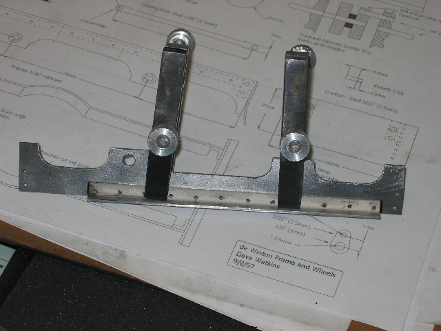
As some of you already know, my next project is a live steam locomotive based on plans Dave Watkins drew up based the de Winton "Idris".
It's taken quite a lot of searching to get together suitable materials for the build to start, but I think I have enough together now.
My loco will be called Fred - after my grandfather, who provided me with a nice piece of copper plate and other odds & ends.
First up, I'll do the loco frame. Please excuse the quality of the photographs; there is something wrong with my camera....
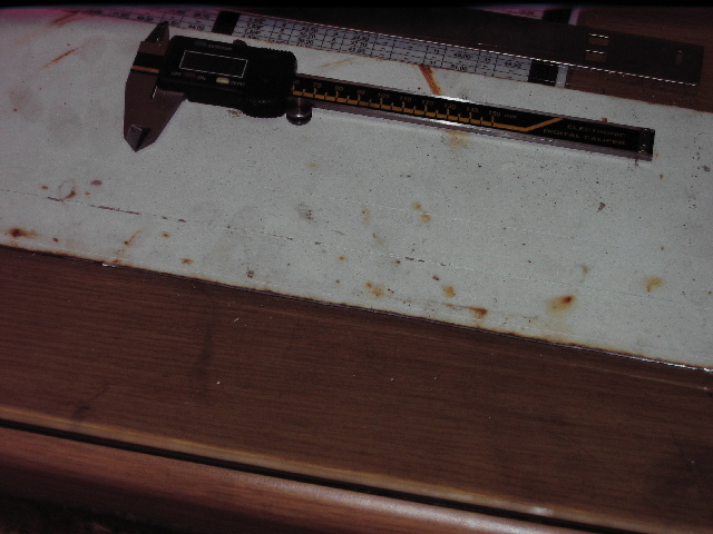
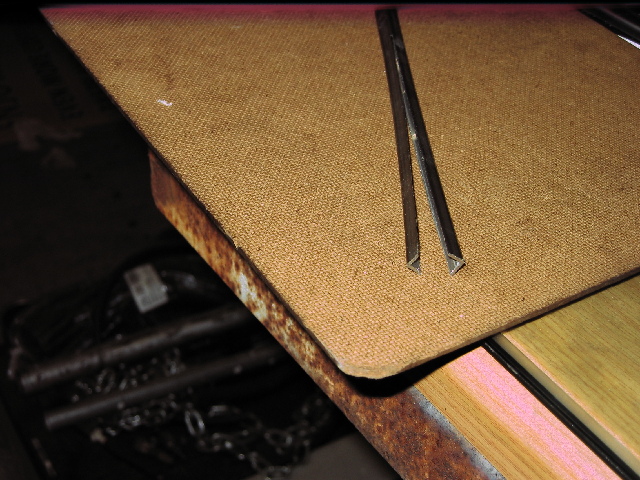
Thursday evening after work I managed to get into the shop for an hour and a half. I started with a piece of 1.6mm plate I got off an old UPS cover:
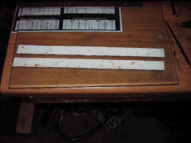
I marked and bandsawed 2 x 24mm wide strips off it - this is oversize so that I can file the sides straight and to the required 22mm width:
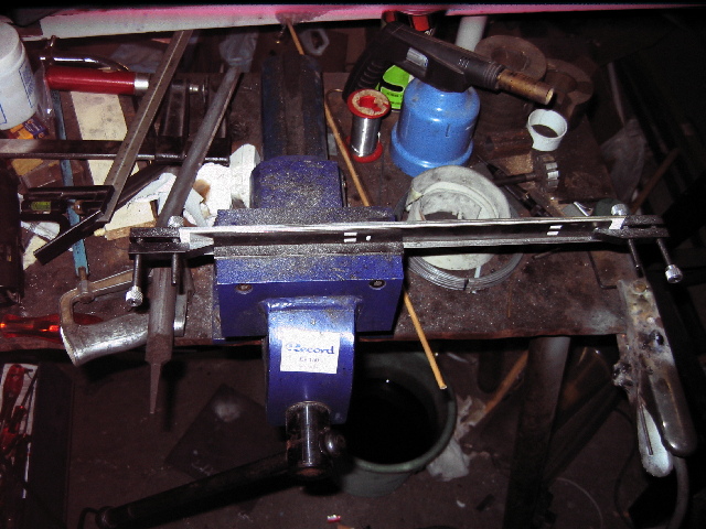
Then I clamped the plates and a guide plate together, mounted the whole assembly in the big vise and settled down to an extended period of filing:
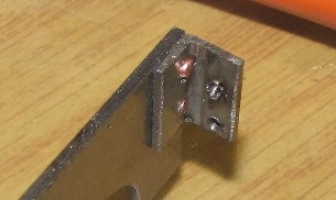
One of the things I have not been able to find is suitable 6mm angle for the frame supports and corner pieces, so some improvisation is needed. At noon today on I started in the shop by sawing some square tubing I got out of an old printer in half to get angles. I did this on the bandsaw, using the table blade groove as a guide. It's blade does not run in the exact center of the groove, but I used this to my advantage to get one "good" piece of angle iron from the cut; the other side warped away:
Some more sweat and filing was then applied to the angle to trim it up.
Part of the reason for my late start today was that I needed to go and get paint stripper from town to get the old paint off the plates. What a waste of time. I don't know what kind of paint was on these plates, but the paint stripper did absolutely nothing to it. So I took the lot outside, and used a blow torch to burn off the paint. Then an extended session with a wire wheel in the drill press to get rid of all the last bits still sticking. A bit of a safety note: On many drill presses (like mine) that use a morse taper shank and jacobs taper on the chuck, one of the two tapers is liable to come loose when trying to use loose running toolbits like a wire wheel. To make sure the jacobs part on my setup does not come loose, I fit the chuck to the shank by heating the chuck in the oven and freezing the shank in the deep freeze, then tapping them together. This pretty much a permanent solution; one is very unlikely to get them apart again. To make sure the morse taper does not come apart, I made a ring with 2 rows of grub screws that secures the shank to the spindle after it is inserted. If anybody wants a picture of this, just shout")
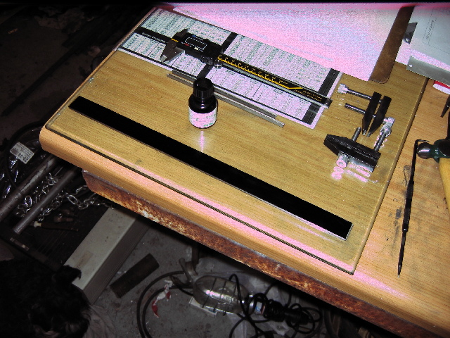
After the plates were clean, I superglued them together, and swiped permanent marker ink over the one face to do the layout:
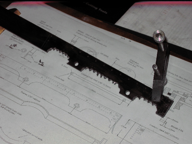
Some quality time with the measuring instruments followed, and then a lot of hole-drilling. Part way through chain drilling for the cut-outs, the heat generated started to melt the superglue and the one end of the plates wanted to come apart, so I had to clamp the plates on that side. I let things cool down and drilled the last couple if holes. More filing still required:
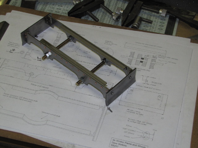
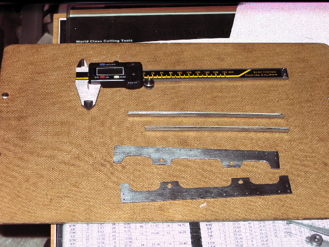
Next up was a lot more filing. It was 34 degrees here today, so it was hot job to do the filing, and once done, I called it a day. End of day's work - not much for all the time spent! - Frame sides done, and some 6mm angle:
Regards, Arnold
As some of you already know, my next project is a live steam locomotive based on plans Dave Watkins drew up based the de Winton "Idris".
It's taken quite a lot of searching to get together suitable materials for the build to start, but I think I have enough together now.
My loco will be called Fred - after my grandfather, who provided me with a nice piece of copper plate and other odds & ends.
First up, I'll do the loco frame. Please excuse the quality of the photographs; there is something wrong with my camera....
Thursday evening after work I managed to get into the shop for an hour and a half. I started with a piece of 1.6mm plate I got off an old UPS cover:
I marked and bandsawed 2 x 24mm wide strips off it - this is oversize so that I can file the sides straight and to the required 22mm width:
Then I clamped the plates and a guide plate together, mounted the whole assembly in the big vise and settled down to an extended period of filing:
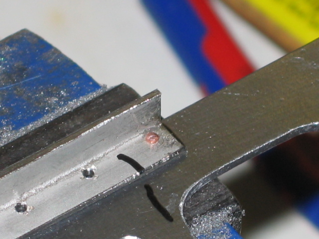
One of the things I have not been able to find is suitable 6mm angle for the frame supports and corner pieces, so some improvisation is needed. At noon today on I started in the shop by sawing some square tubing I got out of an old printer in half to get angles. I did this on the bandsaw, using the table blade groove as a guide. It's blade does not run in the exact center of the groove, but I used this to my advantage to get one "good" piece of angle iron from the cut; the other side warped away:
Some more sweat and filing was then applied to the angle to trim it up.
Part of the reason for my late start today was that I needed to go and get paint stripper from town to get the old paint off the plates. What a waste of time. I don't know what kind of paint was on these plates, but the paint stripper did absolutely nothing to it. So I took the lot outside, and used a blow torch to burn off the paint. Then an extended session with a wire wheel in the drill press to get rid of all the last bits still sticking. A bit of a safety note: On many drill presses (like mine) that use a morse taper shank and jacobs taper on the chuck, one of the two tapers is liable to come loose when trying to use loose running toolbits like a wire wheel. To make sure the jacobs part on my setup does not come loose, I fit the chuck to the shank by heating the chuck in the oven and freezing the shank in the deep freeze, then tapping them together. This pretty much a permanent solution; one is very unlikely to get them apart again. To make sure the morse taper does not come apart, I made a ring with 2 rows of grub screws that secures the shank to the spindle after it is inserted. If anybody wants a picture of this, just shout
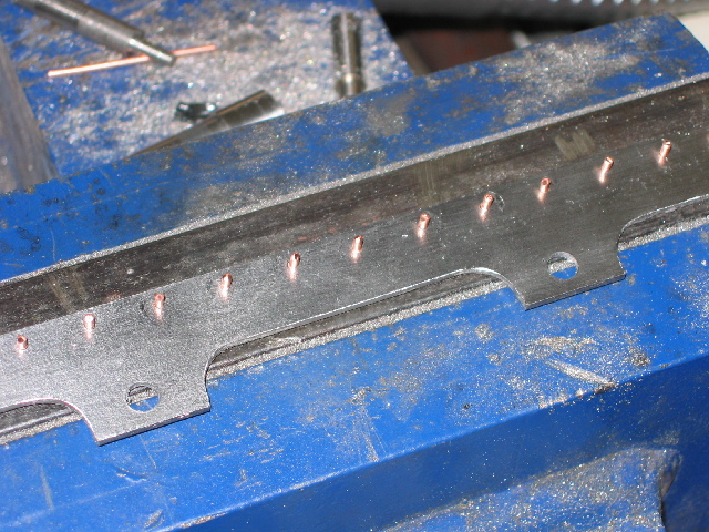
After the plates were clean, I superglued them together, and swiped permanent marker ink over the one face to do the layout:
Some quality time with the measuring instruments followed, and then a lot of hole-drilling. Part way through chain drilling for the cut-outs, the heat generated started to melt the superglue and the one end of the plates wanted to come apart, so I had to clamp the plates on that side. I let things cool down and drilled the last couple if holes. More filing still required:
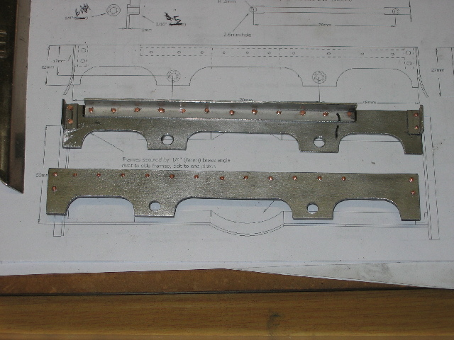
Next up was a lot more filing. It was 34 degrees here today, so it was hot job to do the filing, and once done, I called it a day. End of day's work - not much for all the time spent! - Frame sides done, and some 6mm angle:
Regards, Arnold