


Hi All !
I need suggestions.
In the process of using the new lathe, there are a few ideas I want to add to the lathe
This is one of those ideas
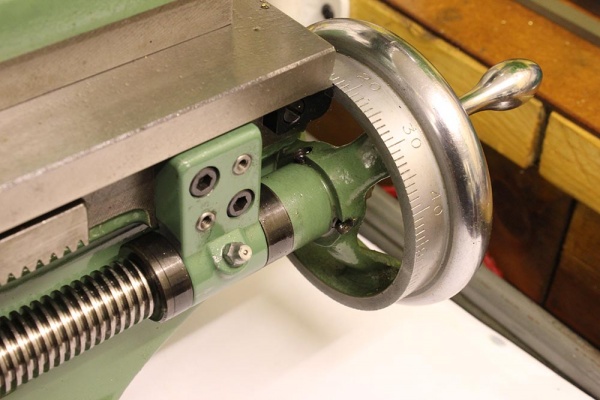
- Moving the tool table with small distances like 0.3 0.5 ...mm is really difficult to be precise with rack and pinion

I don't want to change the existing lead screw because I also need it during machining. So I want to add another set of lead screws as shown in the picture. Of course, when installing a new lead screw, it requires a mechanical or electrical mechanism, then I can only choose 1 of the 2 lead screws. : I can do that

I need suggestions.
What thread pitch should I choose for lead screws?
And do you have any other ideas?
Thank you !
I need suggestions.
In the process of using the new lathe, there are a few ideas I want to add to the lathe
This is one of those ideas
- Moving the tool table with small distances like 0.3 0.5 ...mm is really difficult to be precise with rack and pinion
I don't want to change the existing lead screw because I also need it during machining. So I want to add another set of lead screws as shown in the picture. Of course, when installing a new lead screw, it requires a mechanical or electrical mechanism, then I can only choose 1 of the 2 lead screws. : I can do that
I need suggestions.
What thread pitch should I choose for lead screws?
And do you have any other ideas?
Thank you !
 .
.