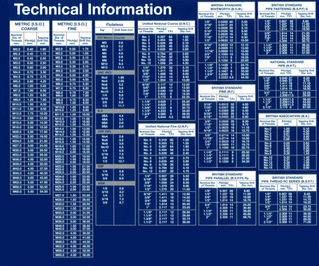
Converting Imperial and Metric threads to U.S. Threads

Home Model Engine Machinist Forum

Help Support Home Model Engine Machinist Forum:

This site may earn a commission from merchant affiliate links, including eBay, Amazon, and others.
B

Bogstandard

Guest
Just to help the newcomers and maybe a few not too new, here are a couple of charts to assist in the choice of converting to US threads if you come across a plan that uses metric or obscure model engineering threads.
Just co-relate by using the BA conversion. eg 2.5mm relates to 7BA. Then 7BA relates to 3-48.

modelengineer.jpg


US.threads.jpg


John
 
So I'm poking around the forum looking for a metric-to-closest-imperial thread chart and found this topic.. but the pics have been lost. Anybody got 'em saved somewhere?
 
Hi Shred,

I can't find the originals, but these might help and you will be able to save and print them out

John

Big Tapping Chart.jpg


Tap Chart.jpg


Thread Forms.jpg


Faults & Causes.jpg
 
Here's one I made up some time ago.

British Association Closest American
Threads Threads

BA OD TPI PITCH THREAD OD
Size (in) (mm) (in)

16 0.031 134.0 0.19
15 0.035 121.0 0.21
14 0.039 110.0 0.23
13 0.047 102.0 0.25
12 0.051 90.9 0.28 0-80 0.060
11 0.059 82.0 0.31
10 0.066 72.6 0.35 1-72 0.073
9 0.075 65.1 0.39
8 0.087 59.1 0.43 2-56 0.086
7 0.098 52.9 0.48 3-48 0.099
6 0.110 47.9 0.53 4-48 0.112
5 0.126 43.0 0.59 5-44 0.125
4 0.142 38.5 0.66 6-40 0.138
3 0.161 34.8 0.73 8-32 0.164
2 0.185 31.4 0.81 10-32 0.190
1 0.209 28.2 0.90 12-28 0.216
0 0.236 25.4 1.00 1/4-28 0.250

Notes from ME-05/05/95-529 Post Bag letter by Jim Nicholson
Full series runs from 0 to 22.
Thread angle = 47.5 deg.
Crest and root radii = 0.18p (p=pitch)
Pitches are calculated as p(mm) = 0.9^n (n=number of thread in BA series)
Diameters are calculated as D(mm) = 6p^1.2
Running:

FOR N=22 TO 0 STEP -1 : P=0.9^N : D=6*P^1.2
PRINT USING "## #.### ###.# #.###";N;D/25.4;25.4/P;P
NEXT

produces:

N OD TPI PITCH
(in) (mm)
22 0.015 257.9 0.098
21 0.017 232.1 0.109
20 0.019 208.9 0.122
19 0.021 188.0 0.135
18 0.024 169.2 0.150
17 0.028 152.3 0.167
16 0.031 137.1 0.185
15 0.035 123.4 0.206
14 0.040 111.0 0.229
13 0.046 99.9 0.254
12 0.052 89.9 0.282
11 0.059 80.9 0.314
10 0.067 72.8 0.349
9 0.076 65.6 0.387
8 0.086 59.0 0.430
7 0.097 53.1 0.478
6 0.111 47.8 0.531
5 0.126 43.0 0.590
4 0.142 38.7 0.656
3 0.162 34.8 0.729
2 0.183 31.4 0.810
1 0.208 28.2 0.900
0 0.236 25.4 1.000
 
Thanks guys.. What I was looking for was a chart like so (much like Marv's first, but with an additional metric column):

Metric..........Nearest BA.......Nearest UNS
----------------------------------------
M2.... 0.078"... 9BA (.075") ... #2 (.086")
M3.... 0.118"... 6BA (.110") ... #4 (.112")

and so on, so when I'm looking at a metric print I can swap in #4-40 instead of a M3 (or 4-48 for M3f)

I finally found one of a sort (I'm still working out what half of it's for, but what I need is on there): http://www.allcap.co.uk/Conversi.htm
 
Here is one that has almost too much information as it has all common threads plus watch threads in order of major diameter.

http://www.watchman.dsl.pipex.com/thread.html

It can be downloaded in Excel format so you can modify it if you like.
 
When one wants a specialized chart such as this, it's easier to generate it than to try to find a source for a readymade one.

Ten minutes of programming yielded a program that produced the chart below.

Column A is the screw OD in mm.
Column B is the closest BSA screw number (BSA numbers only go to a maximum of zero (typical idiotic inverted, closed end scale) so a "-1" indicates that there is no equivalent BSA number.
Column C is the nearest numbered screw size (another idiot closed end scale). -1 refers to size "00" and -2 refers to size "000". For sizes greater than #12 (have you ever seen a #14 tap?), the decimal equivalent of the millimeter size in column A is given. Thus, for example, the closest screw size to 6.25 mm is 0.246" and one would presumably use a 1/4-20 or 1/4-28 thread.

If you want the table with a larger range or smaller step size in millimeters, let me know. It's a simple matter of changing a number or two in the code and recompiling and rerunning the program.


A......B.......C
-----------------------
0.500..20.000..-2.000
0.750..16.000..-2.000
1.000..14.000..-2.000
1.250..12.000..-1.000
1.500..11.000..0.000
1.750..10.000..1.000
2.000..9.000..1.000
2.250..8.000..2.000
2.500..7.000..3.000
2.750..6.000..4.000
3.000..5.000..4.000
3.250..5.000..5.000
3.500..4.000..6.000
3.750..4.000..7.000
4.000..3.000..7.000
4.250..3.000..8.000
4.500..2.000..9.000
4.750..2.000..10.000
5.000..1.000..11.000
5.250..1.000..11.000
5.500..1.000..12.000
5.750..0.000..12.000
6.000..-1.000..12.000
6.250..-1.000..0.246
6.500..-1.000..0.256
6.750..-1.000..0.266
7.000..-1.000..0.276
7.250..-1.000..0.285
7.500..-1.000..0.295
7.750..-1.000..0.305
8.000..-1.000..0.315
8.250..-1.000..0.325
8.500..-1.000..0.335
8.750..-1.000..0.344
9.000..-1.000..0.354
9.250..-1.000..0.364
9.500..-1.000..0.374
9.750..-1.000..0.384
10.000..-1.000..0.394
 
Thanks Marv. I figured somebody was trying to be clever making the #14 the same as 1/4", but it seems to not quite be the case.

Anyway, for this particular project all I need is thru about M5 and I have those.

IIRC not every metric step is 'legal' for a thread (much like you don't ever see #7 or #9 in the UNS system), so it might be possible to cut down the chart. The information-design part of my brain thinks there should be a nifty X-Y layout wherin the Y axis goes from say ~0mm to ~25mm on the left side and 0-1" on the right and across the X in between are the various common model-maker thread systems and drill schemes with entries in the correct position for each of the typical sizes in that system. Then you could just slap a ruler across the size you wanted to convert from and at a glance, get the nearest up and down in the other systems as well as metric and imperial conversions and applicable drills. With some extra mojo, you could even have a column for tapping drill sizes.


Shred,

The program is just a tool to automate the process of developing the equivalencies between the three systems. Extract the information you want and arrange it however suits you. Given the small number of screw sizes used in model making, making a personal chart shouldn't require much time.

I know that not every multiple of 0.25 mm is a standard metric thread but, from a programming point of view, it's easier to just step through all the values and then let the user discard whatever he doesn't want.
 
Converting Imperial and Metric threads to U.S. Threads: This process involves careful measurement and calculation to ensure compatibility across different systems. By understanding the specifications and utilizing appropriate conversion charts or tools, engineers and manufacturers can seamlessly adapt threads to meet the requirements of U.S. standards, facilitating smoother assembly and interchangeability.
 
There is a part of this story that is missing. It deals with the economics of standards and who sets them. The standards are often based on geometric mathematics as unit are specified in sizes that are reasonable for mass production. Who ever has the most adopted standard as a country has an economic advantage. Therefor you will find that not all metric threads are the same which can come as an ugly surprise. Thread shapes and dimension are chosen for the strength and ease of manufacture and for the most part are very similar in design. However there is the thread which is usually not mentioned and that is a one off design. You are likely to find these in something a blacksmith built and I hope you do not have the unfortunate circumstance of having to replace them! You will also find these threads in some models and they work quite well. Not to long ago I replaced a metric bolt supposedly standard but no one kept it in stock because it was so rarely used no one made them. Had to make it myself
 
As they say- the trouble with standards is there are so many of them!
If I remember correctly, the BSA Bantam (early pommie two-stroke motorcycle) had some 37 different threads on it, including several that were BSA's own design- made maintenance a nightmare.
We always used to say BSA stood for Bits Stuck Anywhere.......
 
If ever did read on books from 1920s. They will talk the metric system and American standards.
Just try the 6203 ball bearing it been for long time.
You can take 3/4" bar stock machine to the 6203 bearing then use a 5/8" Bolt. Very handy for the inch bar stock.

I found a lot of metric bearing that can use inch bar stock.

Dave
 
As they say- the trouble with standards is there are so many of them!
If I remember correctly, the BSA Bantam (early pommie two-stroke motorcycle) had some 37 different threads on it, including several that were BSA's own design- made maintenance a nightmare.
We always used to say BSA stood for Bits Stuck Anywhere.......
If look at quick change gear box. To switch from inch to metric you swith the input. Using all the same gear plus adding a127 gear or 37/47 gear. Now that one dates before WW1.

Now if the metric had something close to inch and foot like using 25 mm and call 1mi and for a for foot use 250mm and call it 1mf.

They did with tons or metric ton.
Metrics would here a long time ago

Dave
 
As a youth of 12 or 13 I owned a BSA Bantam for a while.
It didn’t run & was stuck in 2nd gear when I and a friend got it.
We got it running & rode it round in 2nd gear.
It had a chrome & pale green tank with a rooster decal on either side of the tank as I remember.
And BSA stood for Bastard Stopped Again.
Also had ‘74 Norton Commando 850 Mk1A in the early ‘80’s.
It had a mix of metric & imperial fasteners if I remember correctly.
Don’t get me started on that bike……
 
The BSA Bantam started life as the German DKW. After ww2, the design was given to BSA.
This may go some way to explaining the mixture of threads.
I have a Bantam, a D1 model from 1951.
There are no metric threads on it.
The engine uses Whitworth plus a few specials, while the cycle parts use mostly 26TPI cycle threads and the electrical parts use BA threads.
 
Tug40 said "And BSA stood for Bastard Stopped Again."

Thanks Tug40, that made me laugh- I hadn't heard that one before.
Though back in the 60's it could have applied to most of the pommie bikes we owned- even the new ones!
 
BAS stands for
British Association Screw Threads.

Now British can a pain they use for ⅛ pipe 28TPI we use 27TPI very close and some threads 19TPI most Americans lathes do not have 19TPI threading.

Japan has a odd pipe sizes too. Can be a pain too.

Dave

Most pipes size in world. I stop at 3/4" IPS.
I have purchased 2" XX pipe and does not machine well. Later swathed to Dom tube machine a lot better.
Screenshot_20240304-082639_Edge.jpg
 
Last edited:
Having an actual conversion chart would be the quickest method for metric - imperial or the reverse. But it's easy enough if you've got a tap drill chart. Just find the tap drill size in lets say metric, convert that to it's imperial decimal equivalent, and then find the closest recommended tap drill for an imperial sized thread, and there's your size and thread conversion. Whitworth, BA etc could be done the same. No it won't be exact, but it would be close enough in most cases. In some ways M.E. threads are also used for aesthetic purposes since the much finer threads look closer to the items reduced scale size versus full size. So for that reason there's no exact conversion other than our 4-40 tpi and 8-32 would match well enough for the 40 and 32 M.E. threads. And I'd assume the same could be true for a few metric threads that might be close.

Whitworth and the M.E. threads also have a 55 degree thread flank. Imo 55 or 60 degrees and the various root and crest shapes such as what the BA threads have would probably make no difference for what most of us would be doing. There's also lot's of 40 tpi taps and dies available with that 60 degree flank angle that are listed as special thread in most of the larger tool supplier catalogs. While considered non standard, a lot of those same suppliers have them on the shelf for not much more than what the usual taps and dies are priced at. There a handy source when building something like your own boring head and might want that much larger diameter 40 tpi for measurement and adjustment purposes on the slide. Although I believe the M.E. series does go up to 1/2" x 40 tpi. But I've also seen non standard and large diameter 60 or even up to 80 tpi listed. Since I don't usually use metric, I don't know if the same might be true for non standard mm pitches.
 

Latest posts

Back
Top