Building a twin cylinder inline i.c. engine.

Home Model Engine Machinist Forum

Help Support Home Model Engine Machinist Forum:

This site may earn a commission from merchant affiliate links, including eBay, Amazon, and others.
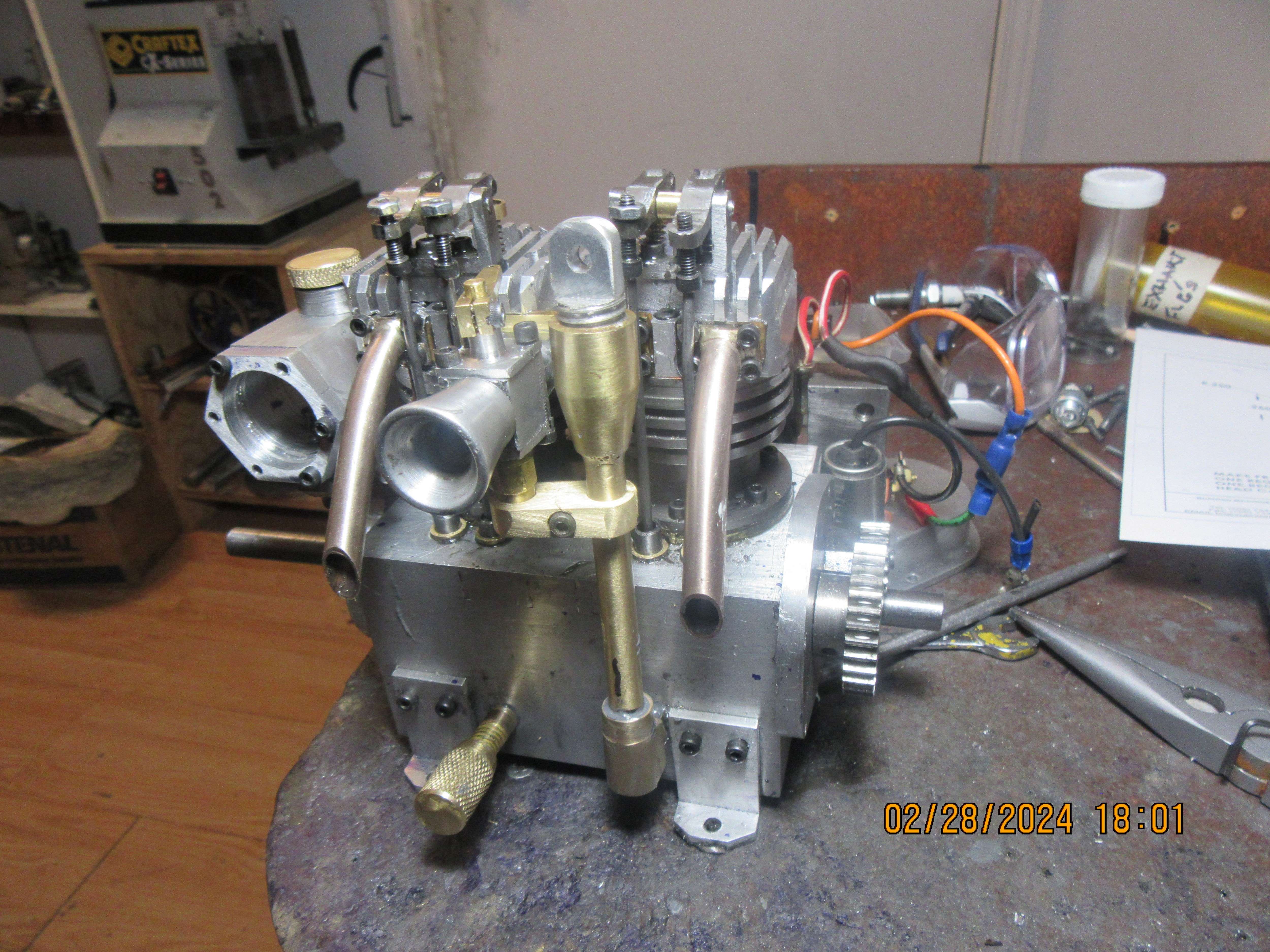
This afternoon seen the lubrication piping finished up, and the tie from the carburetor body over to the oil filler pipe to steady everything up finished and installed. Nothing cosmetic really done yet, everything is still a 'work in progress'.
TOxD84.jpg
 
It's the lock nuts on the adjusters that are not tight and have allowed the adjusters to work their way into the rockers. You can see all the nuts are on the end of the screws not against the rockers.
 
It really was a matter of poor adjustment. It only took a minute to adjust the bolt in the rocker arm to hold the push-rod so it wouldn't jump out. I may set the valve adjustment and timing later today.
 
Wowza!!--I don't think I have anything left to machine. I can't do anymore to my gas tank until the clear lenses for the ends arrive here. I may mount an illuminated on/off switch on a bracket. Setting ignition timing is easy. Setting the valve timing is always an exercise, but since I can set each cam individually it may not be as large a problem as I anticipate. I will be using my "Starter Table" that I built earlier this year to start the engine with. Wish me luck.---Brian
 
Fire in da hole!!! This morning I bought an illuminated switch and built a bracket for it, and although it's not wired "for pretty" it is wired for first run. I've done something slightly different with the switch for this engine. Previously I used a plain toggle switch with two leads running from the switched side, one to the coil and another one thru a red light and then to ground. That way I knew when the switch was turned on and the light didn't flicker on and off as the points opened and closed. In this case I have used an illuminated switch, which is wired slightly different but still gives good indication as to whether the switch is on or off.
7EcQJ9.jpg
 
This morning I just didn't feel like tacking the valve timing.--However--The electric starting table didn't have any holes tapped in the top plate to suit this particular engine, so I got everything lined up properly and drilled/tapped holes to let me bolt this engine down. The starter turns the engine over very well, and as soon as I get my o-ring seals for the ends of the gas tank it will be installed and plumbed and the valve timing will be set. The only thing on this engine that gives me any concern are the cams. I truly do wish that someone out there in the wide world made a business of cnc machining cams for model engines. Once a machining profile was established then you could machine forty or sixty cams at one run, thus keeping the price down to where hobby guys could afford to buy them.
uVowkx.jpg
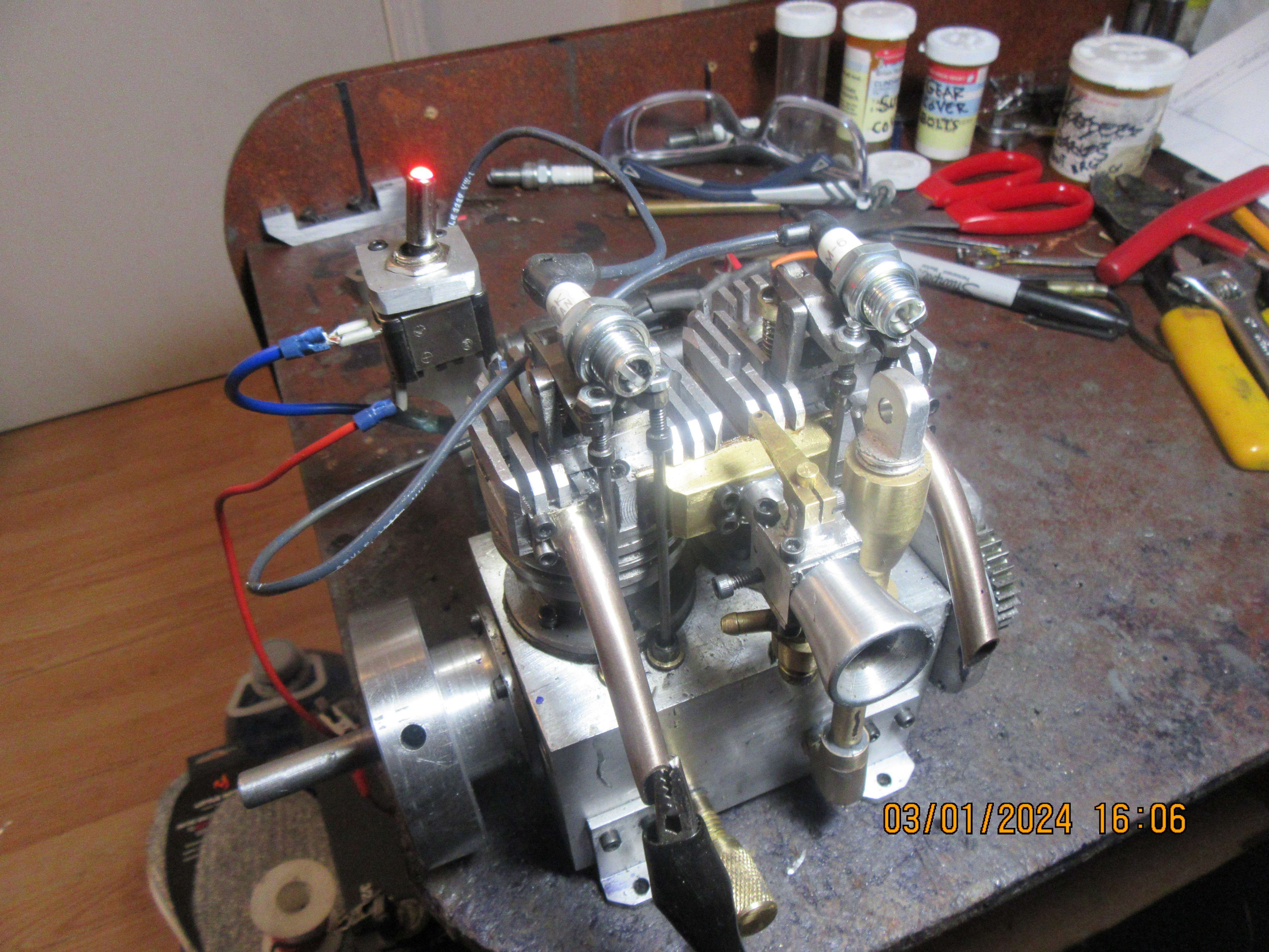
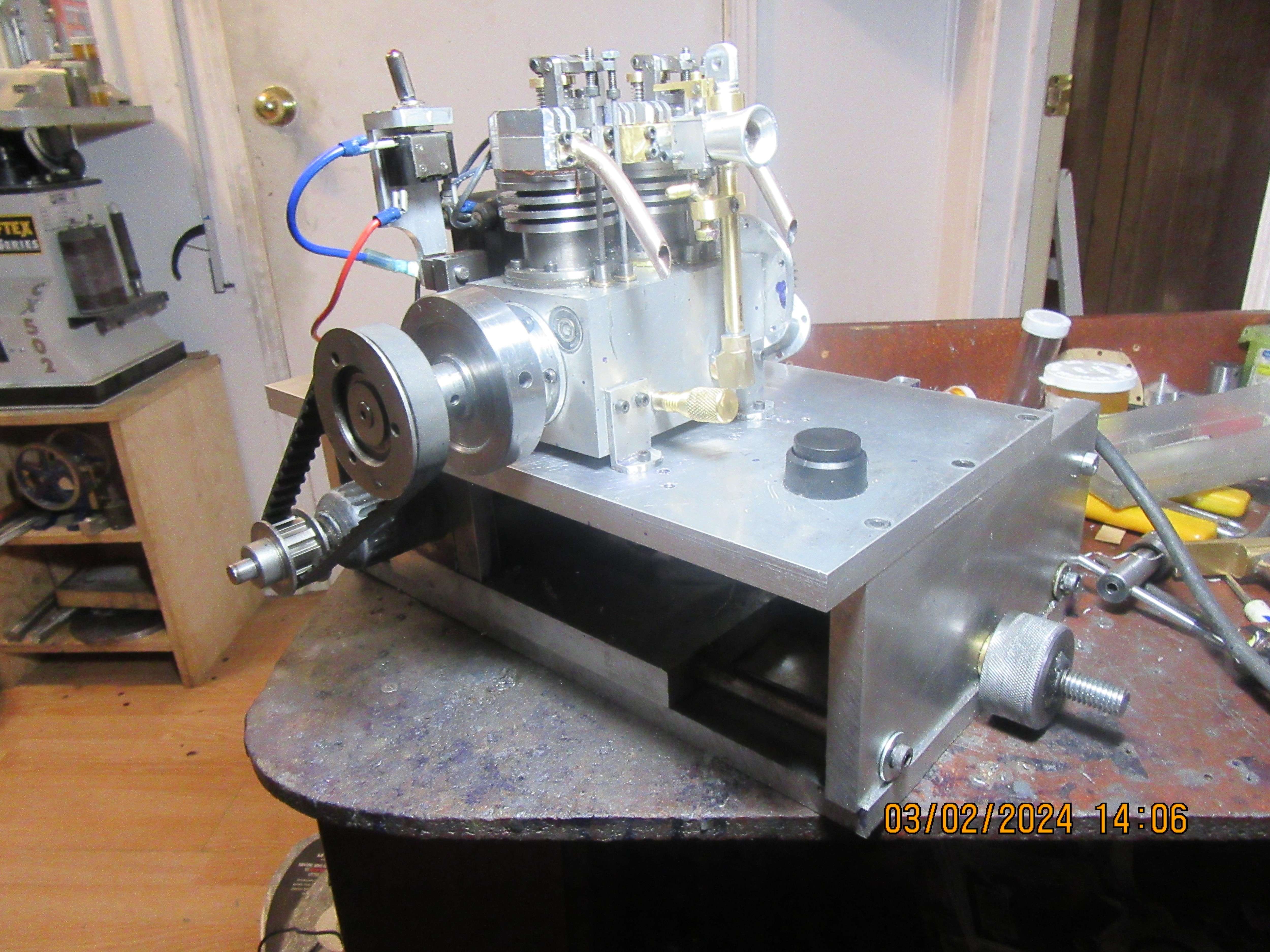
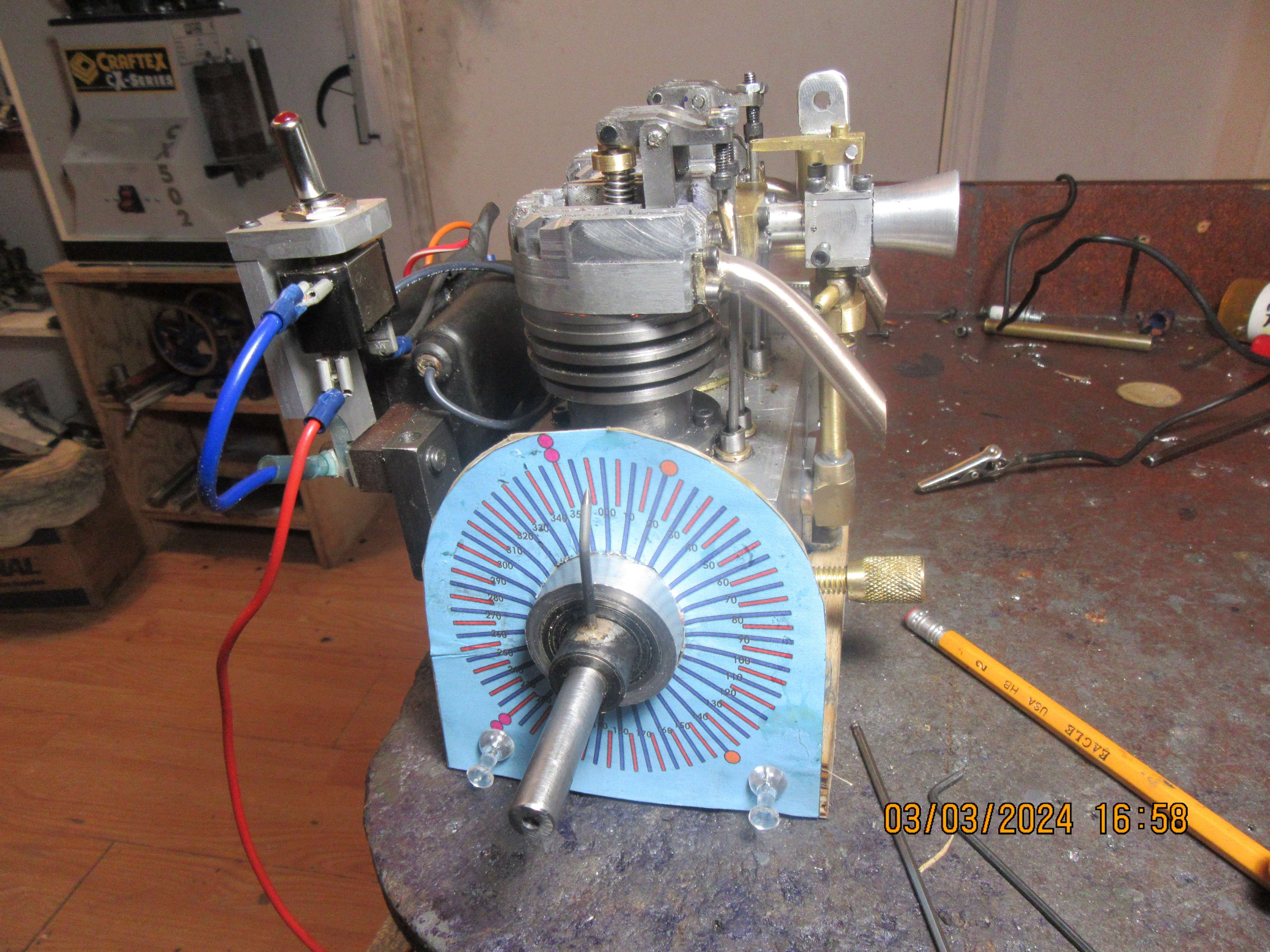
Looking good Brian! I'm looking forward to seeing this engine running. Keep up the great work.
All the best.
Andrew
 
Today I haven't worked too hard---but I have worked some. What you see here is my timing dial mounted to a piece of 3/4" plywood from my scrap box. Both pistons are at top dead center and the timing pointer is pointing at zero on the dial. The piece of 3/4" plywood is bolted to the engine base and has the center cut out so that I can reach in and access the cams to place them in the correct angular orientation to the crankshaft. The sump plate for the engine is removed in this application. First thing I will do is ensure that there is .005" to .010" clearance between the rocker arm and the end of the valve, when the tappet is not "up" on the cam. Then I will rotate the crankshaft until the indicator points at the correct angle, before top dead center or before bottom dead center and set the cams so that they are just beginning to lift the pushrods and move the rocker arms, then lock them in place with the set screws which are part of each cam. This will be done for all four cams. Since the pistons fire alternately, the settings of the first two cams will be reversed for the second two cams.
jVe1XZ.jpg
 
Just an opinion & maybe the picture angle is exaggerated, but I cant help but thinking the SH cap screws used on the rockers should be screwed in substantially towards the rocker. The pushrod would have to be a bit longer to accommodate, but it would mitigate that steep pushrod angle for the same amount of required valve lift.

I kind of lost track of the ignition timing, will you have both pistons be firing at the same time, or alternating between them at their respective TDC's?
 

Attachments

  • SNAG-03-03-2024 2.39.56 PM.jpg
    SNAG-03-03-2024 2.39.56 PM.jpg
    64.7 KB · Views: 0
Petertha--Thank you for bringing that to my attention. Today I have been rushing around getting info on tabletop cnc machines. Although a lot of tabletop machines say they will cut metal, they really don't do well at all on anything other than aluminum or brass. I don't really have the budget to buy a heavier cnc machining center, but it has been an interesting day. In terms of what I actually did to the engine today---the pushrods I had made from 3/32" streel rod were just that tiny bit too large in diameter to clear the heads of the capscrews holding my intake and exhaust manifolds in place. I machined the heads of these capscrews down until there was barely enough socket left in them to accept a wrench, but they still interfered by a tiny bit with the pushrods. So----I drove across town to Barrie's only hobby shop and bought a three foot length of steel rod that measures at 0.078" diameter??? and it was just enough to get me some clearance. Three of the rocker arm and pushrods are working fine, and I have them adjusted for 0.005" clearance between the rocker arm and the end of the valve when the tappet is not "up" on the cam. One remains Oinky (that's a technical term) and I may have to put a stronger valve spring on that one valve, but damned if I know why.
 
Actually I must have been asleep at the switch with my sketch. The pushrods will only push 'up' to open the valves from what I assume is the present valve closed position, so the resultant pushrod angle wont be as exaggerated as I first showed. But the general guidance is the same. Its mechanically more efficient to minimize the pushrod deviation angle through valve opening. What can also happen is the ball end milled into adjuster SHCS is deeper than the radius of the pushrod ball which gives some security. But depending on the action angle, the edge of the socket hole can then interfere with the cylindrical portion of the pushrod itself. That's why sometimes you see a tapered profile of the pushrod end ahead of the ball end, or the socket side is conically relieved a bit to provide clearance. The pushrod is both displacing & rotating in 3D space so makes it kind of hard to guestimate.
 

Attachments

  • SNAG-04-03-2024 8.03.54 PM.jpg
    SNAG-04-03-2024 8.03.54 PM.jpg
    129.9 KB · Views: 0
What peter says is why your rods are hitting the side of the socket heads, if the screws are further in then they won't be at such an angle. It will also reduce the "lift" of your cams as the rod needs to move further to give the same opening that it would if the screw was hearer the rocker arm added to the lash gap you then get reduced duration. You can always open up the socket with an 1/8" ball nose cutter.

I don't know how you are retaining the pivot pins in your rockers but if you used loctite make sure none is making the rocker hang up or that the width of the bearings is not greater than the width between supports. EDIT looking again you have not used bronze bearings for the rockers, it's just a brass spacer I can see so make sure that is not too long and making the rocker arms rub on the support bracket as the bearings are intended to protude and stop that happening.

rockers.JPG


Screws should be close as possible like this

DSC02503.JPG


78thou sounds like 2mm nominal but you could have just turned down the end of the thicker rods you already had.
 
Last edited:
I am a fan of the thinnest practical pushrods, as this reduces mass, accelerating forces, and contact wear.
But, like Petertha, I am also a fan of the tangential contact point between push-rod and rocker socket, as this minimises the side-wise motion of the rocker end of the push-rod... Mid-stroke of the cam lift should be the point at which the push-rod is perpendicular to the line between the contact point and centre of rocker spindle. And the contact point is level with the spindle. But it is not absolutely necessary, and for various reasons, many engines have worked away from the ideal. E.G. a lot of radial engines had cam follower tappet blocks close together, buy the rocker ends were further apart, and further away from the centre line of the bore, so the ideal could not be met in any direction. But Messrs Pratt N Whitney et al made long lasting aero engines that way anyhow. But I would make the socket screws a bit shorter and push-rods equally longer, just because it may solve he issues Brian is experiencing?
I owned a Triumph motorcycle that after a minor disaster had broken some tappets (Cam followers). - Wrong bolts fitted by the previous owner. = But the only available parts were from later engines, so I bought those, with push-rods I had to adjust in length and reduce diameter on the lathe at the rocker socket end.... to avoid a foul just like Brian's tribulations...
I sympathise with the foul and fiddle that CAD doesn't indicate!
K2
 
Foul and fiddle can be indicated with CAD as you can get it to analyse the assembly and highlight any clashes.
 
Hello everyone

Maybe the following pictures of one of my model airplane engines will help.
It's an old OS-FS60 four-stroke engine from the early 1980s.
In the pictures you can see the geometry of the rocker arms and the closed and open position of the inlet valve.
Note the angle and position of the support and pivot points.

Dieter


OS-FS 60 engine

OS-FS60.jpg


Inlet valve closed

OS-FS60-intake-valve-closed.jpg


Inlet valve open

OS-FS60-intake-valve-open.jpg
 
Forgive me--I've spent the morning playing on my cad system. One of the pioneers of model engine building Graham Meek did an excellent presentation of how he machined a cam with flank radii. This looks a bit crazy, but it works. Machine one side of the cams, flip them over and machine the other side. This only puts a radius on the flanks, but it is still fascinating.
qncpRG.jpg
 
Last edited:
Back
Top