What, you have opticians that can grind a lens perimeter, opticians around here buy their lenses from one of three companies that own the industry?Hello everyone
I also once had the problem that I needed round glass panes to my desired dimensions.
I wanted to turn a rectangular volt and ampere display into a round display to get a vintage design.
A friend of mine owns an optician's shop and he makes glasses.
He has a CNC grinding device where he can grind the shape of the glasses frame from the lens blanks.
I bought a small picture frame with a 2 mm thick glass pane.
He broke this pane of glass into four squares.
He then ground the round glasses from the squares to my desired diameter.
Just ask an optician's shop whether they can grind your round glass panes too.
Such a grinding process only takes a few minutes.
Unfortunately I don't have any pictures of the CNC grinding machine.
With the pictures I show you the way from the rectangular to the round volt display.
Regards
Dieter
You are using an out of date browser. It may not display this or other websites correctly.
You should upgrade or use an alternative browser.
You should upgrade or use an alternative browser.
Building a twin cylinder inline i.c. engine.
- Thread starter Brian Rupnow
- Start date

Help Support Home Model Engine Machinist Forum:
This site may earn a commission from merchant affiliate
links, including eBay, Amazon, and others.
After the eye test and determining the necessary correction, the optician in Germany orders the lenses from the manufacturer.
The new corrective lenses of the glasses are ready for vision correction and have a round outer shape of around 60 to 70 mm. (approximately 2.36 to 2,75 in)
With the CNC grinding machine he can scan the shape on the glasses frame.
This shape is then transferred to the lenses using the CNC grinding machine.
The lenses are ground into the glasses frame.
This is one of the tasks of an optician in Germany.
In my small town where I live.
With a total population of around 50,000,
we have around 8 different small optical shops within a radius of around 5 miles.
Regards
Dieter
Today is cam day. Yesterday I purchased a 12" length of 01 steel (these cams will be hardened). The first step was to turn the o.d. to 0.448" which coincidently is the largest diameter of the cam nose. Next step was to drill and ream the center hole to 0.188". I have parted off two 2" lengths of material and that should give enough material to build all four cams that I need. All of the machining work on these cams must be completed before they are heat treated.
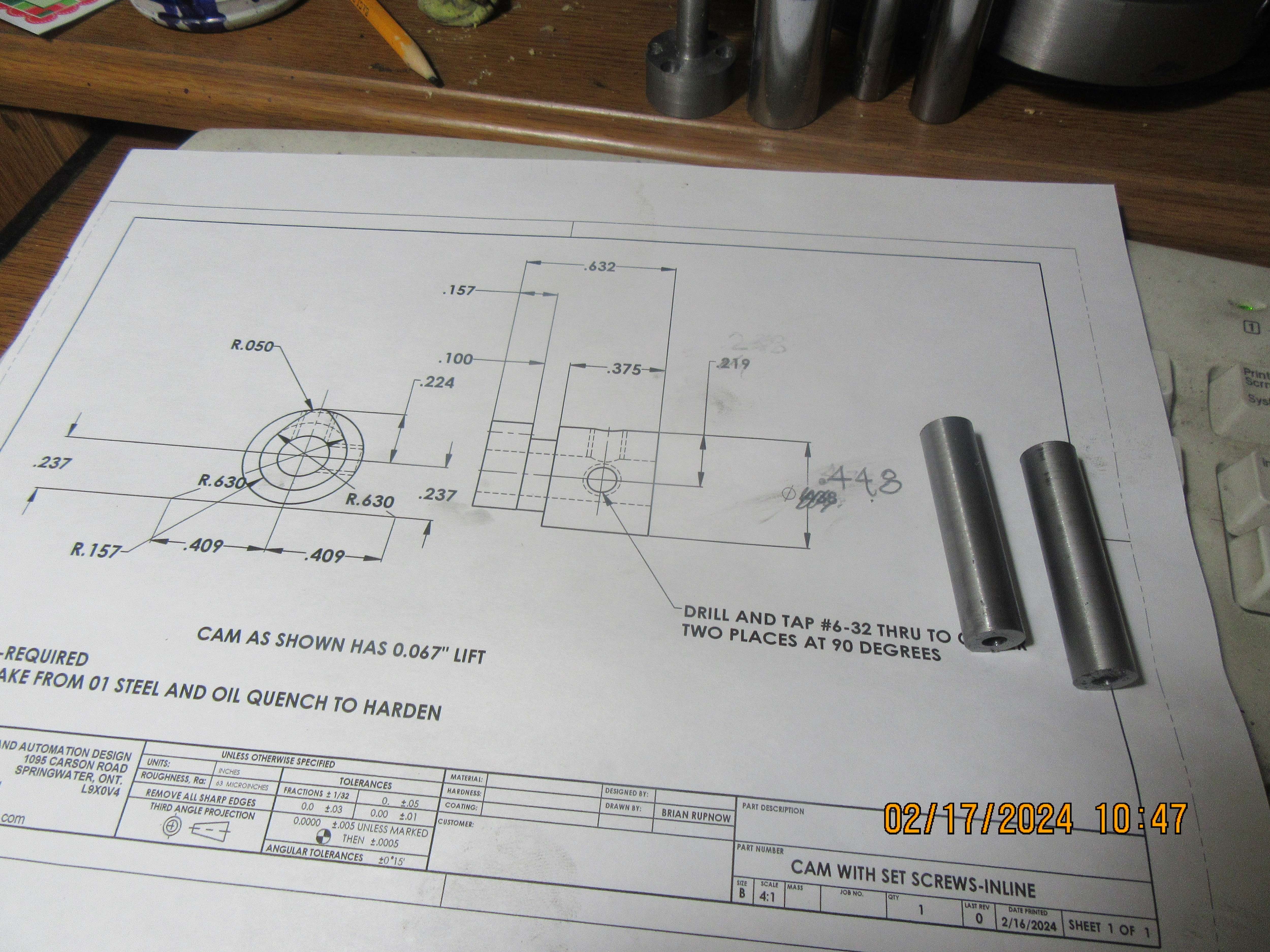

Of all the things I do, and I do a lot--I especially hate making cams. I know the formula for calculating cams. I know half a dozen ways to make the cams. The way I make them on my milling machine works for me, but they take forever to make and are a great pain in my a$$. I started this morning at 8:00 and it's now 4:00 in the afternoon. That's 2 hours per cam, which really isn't bad, but I'd rather kiss a snake than make a cam. If the lord loves me and I get these little rascals heat treated without melting anything, I will be a happy man!!!

Bentwings
Well-Known Member
I just had to assemble the crankshaft with the con rods and pistons to see if everything went round and round and up and down without hitting any obstructions. I'm very pleased with the results.---Brian
Vey nice good job
Sadly there are only two practical alternatives to making a cam: use a sleeve valve (which has its own issues, to say the least) or build a 2-stroke (and they are the work of the devil). So we must grit our teeth and persevere.Of all the things I do, and I do a lot--I especially hate making cams. I know the formula for calculating cams. I know half a dozen ways to make the cams. The way I make them on my milling machine works for me, but they take forever to make and are a great pain in my a$$. I started this morning at 8:00 and it's now 4:00 in the afternoon. That's 2 hours per cam, which really isn't bad, but I'd rather kiss a snake than make a cam. If the lord loves me and I get these little rascals heat treated without melting anything, I will be a happy man!!!

Something to consider for future engines is that it's common for small engines to use the exact same cam lobe for both intake and exhaust, they just run two rockers on the one lobe and space them apart to get the timing right. You could halve the number of cams you have to make.
ajoeiam
Well-Known Member
Sadly there are only two practical alternatives to making a cam: use a sleeve valve (which has its own issues, to say the least) or build a 2-stroke (and they are the work of the devil). So we must grit our teeth and persevere.
Something to consider for future engines is that it's common for small engines to use the exact same cam lobe for both intake and exhaust, they just run two rockers on the one lobe and space them apart to get the timing right. You could halve the number of cams you have to make.
For his 'steam' engine a Mr Dan Gelbart has a rather interesting solution - - - he uses electronic timing - - no cams.
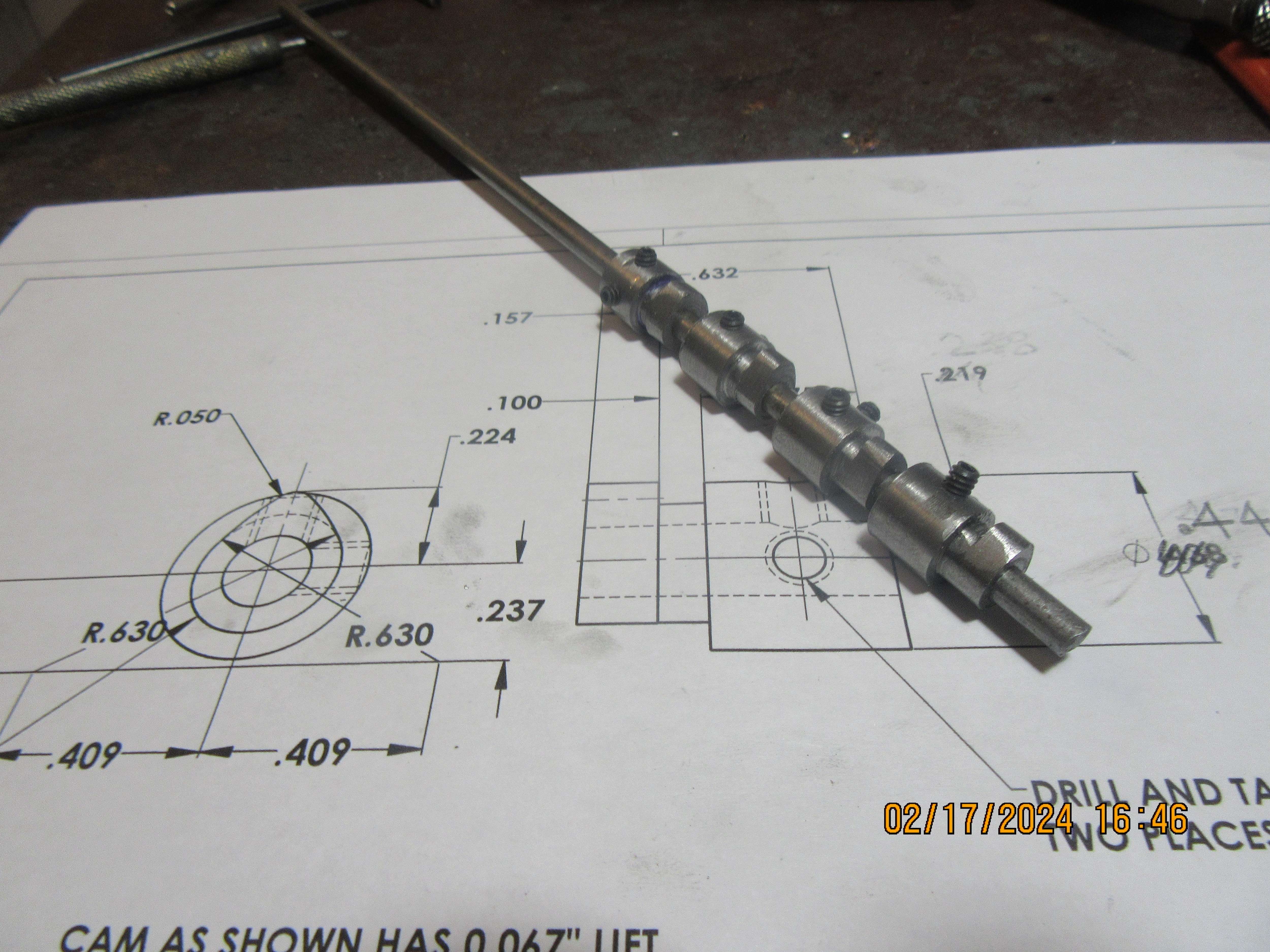
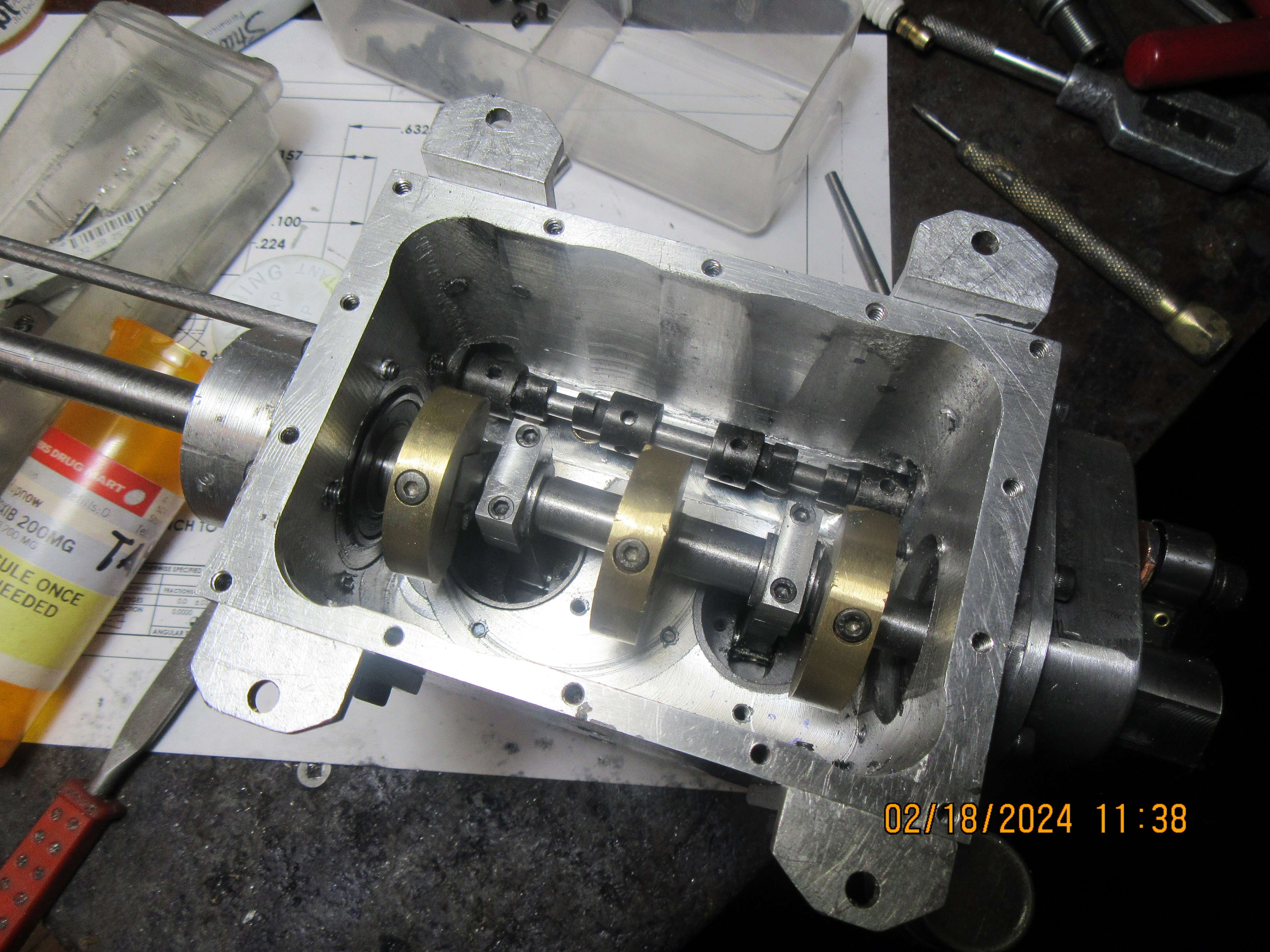
The cams are machined, heat treated, and installed. One cam was uglier than usual, so I didn't heat treat it until I had worked my magic on it with a flat file to bring it's contour into a match with the other three cams. I didn't have quite enough room between the camshaft and the underside of the crankcase, so I removed 0.060" with a 5/8 two flute endmill. The cams fit, the camshaft fits, and tomorrow I have to go to my bolt supplier and buy some #6 socket head set screws x 1/8" long because all currently have are 3/16" long and they stick out far enough even when tightened to prevent the cams from rotating. The tappet guides were pressed into the crankcase, and although the press fit was very light, the tappets no longer fit into the tappet guides. I have loctited a piece of 3/16" round material into the center of each tappet, long enough that I can set each tappet up in my lathe and either sand or grind the outset diameter of the tappet so they once more fit into the guides with a light sliding fit.

Brian, I generally buy my screws as long as possible, they don't cost much more when buying them by the box of 100, and then shorten as needed.
Sadly there are only two practical alternatives to making a cam: use a sleeve valve (which has its own issues, to say the least) or build a 2-stroke (and they are the work of the devil). So we must grit our teeth and persevere.
I've done 4-strokes using an eccentric with a 2:1 epicyclic gearbox in the middle. Also have an eccentric on the crankshaft and a star wheel for another engine. Both these work just the exhaust valve, the inlet being atmospheric though you could double up if you wanted mechanical operation of both valves
This morning I'm wrapping things up. Everything is machined except for the pushrods. I tried to buy shorter set screws for the cams, but everybody is closed today for "Family Day". I tried to buy some metric o-rings to finish off the gas tank, but again, everybody is closed. About the only outstanding thing is my ignition circuit. I have three different dual coils here from the used snowmobile place I visited last week, and this afternoon I will try and find one which works with old style ignition points. Whichever coil works will need to have a bracket to hold it, but that's only an hours work. For now I think a big clean-up of my workspace is called for.
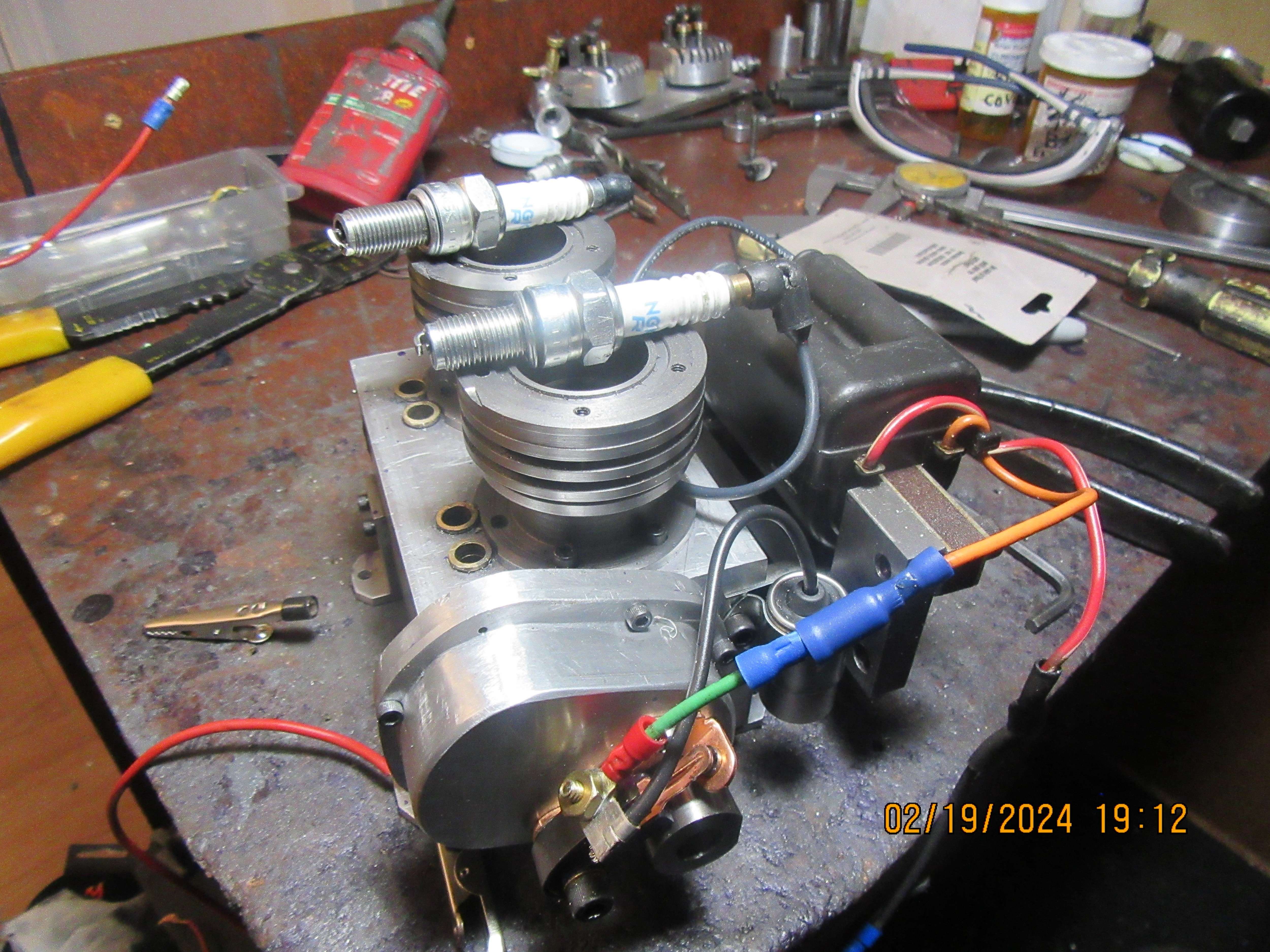
YAY!!!---we got fire!!! Last week I went to a snowmobile wreckers and brought home 3 twin lead coils. I couldn't get any of them to work, and thankfully the owner had said that if I couldn't get them to work he would refund my money. Today, as a last resort, I cannibalized the twin lead coil off my dual opposed cylinder engine, hooked t up to my new inline engine, and it works. This is a big relief.

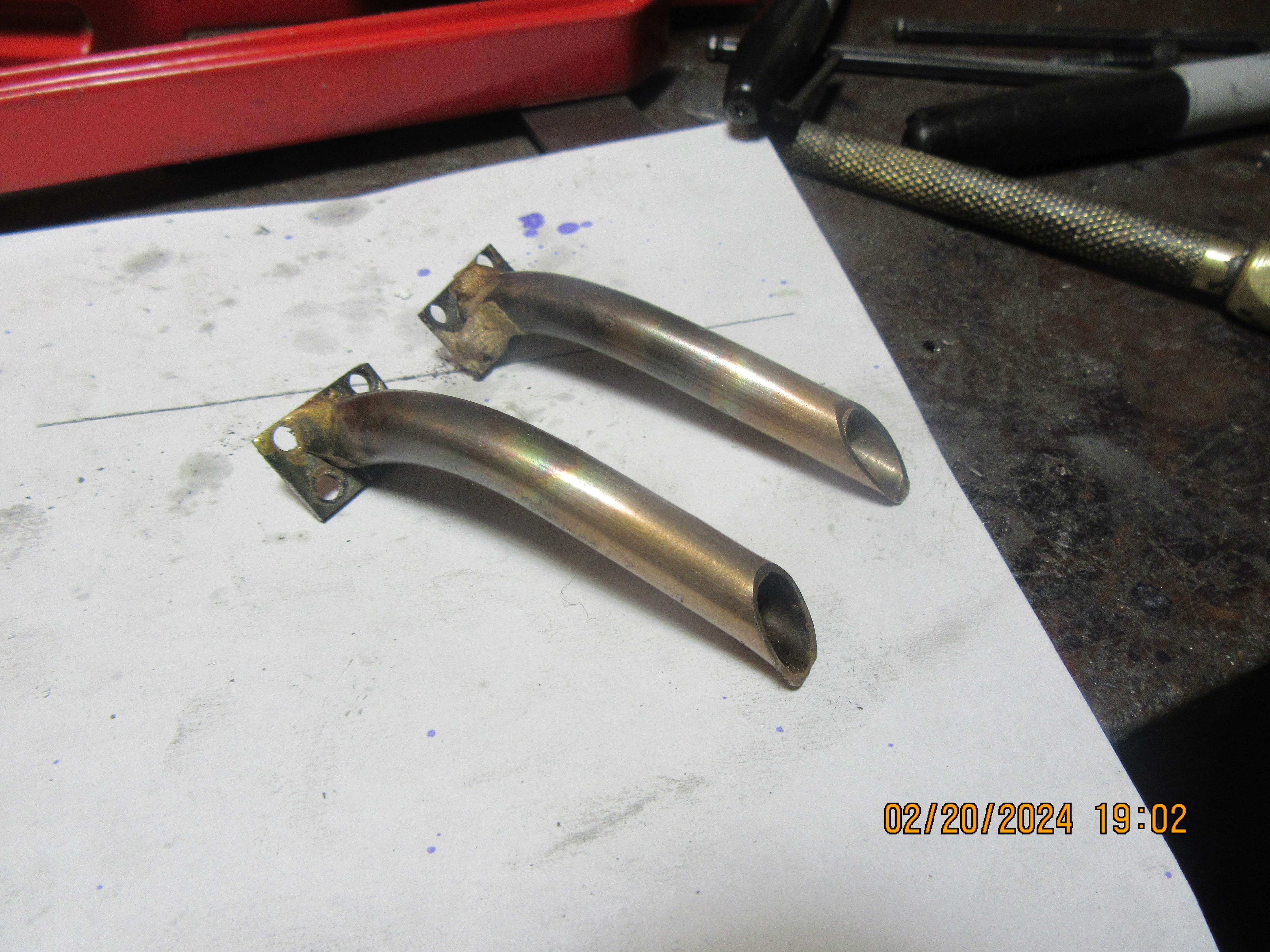
I've just had one of those days where I worked all day and have very little to show for it. I had to make a fixture to align the exhaust flanges with the exhaust pipes for silver soldering. It was one of those fixtures that has to be destroyed to get the parts free from it after soldering. The fixture worked perfectly, but I'm not happy with the quality of the silver soldering job. This is not one of those jobs where you can fake it with J.B. Weld, because it gets too hot while the engine is running. Tomorrow I will try and get more silver soldering done on the parts where they were held by the fixture that positioned them but wouldn't allow me to solder everywhere I needed to.---I hope that makes some kind of sense. Generally speaking, this is where the second silver soldering melts the first silver soldering and everything falls apart.

Hi Brian, I have a similar problem with repairing Old Boilers!
This one now gets damp patches at end seams and the end of a flue tube. "Unknown" silver-solder used originally - probably a regular 650deg C grade - which is what I have to use for repairs. So easy to get a run from the old stuff and Oops! It will leak. Back to the hearth. Try again.
I have to call it "FUN!"...
Ken
What grade of silver solder did you use? welding suppliers will usually offer several, so you might be able to get one with a lower melting point that you can use over the top of the existing solder without melting the joint.I've just had one of those days where I worked all day and have very little to show for it. I had to make a fixture to align the exhaust flanges with the exhaust pipes for silver soldering. It was one of those fixtures that has to be destroyed to get the parts free from it after soldering. The fixture worked perfectly, but I'm not happy with the quality of the silver soldering job. This is not one of those jobs where you can fake it with J.B. Weld, because it gets too hot while the engine is running. Tomorrow I will try and get more silver soldering done on the parts where they were held by the fixture that positioned them but wouldn't allow me to solder everywhere I needed to.---I hope that makes some kind of sense. Generally speaking, this is where the second silver soldering melts the first silver soldering and everything falls apart.

It would be better to try and reflow whats there so it flows properly and forms a small neat fillet rather than blobs. Should flow more like this and need minimal clean up
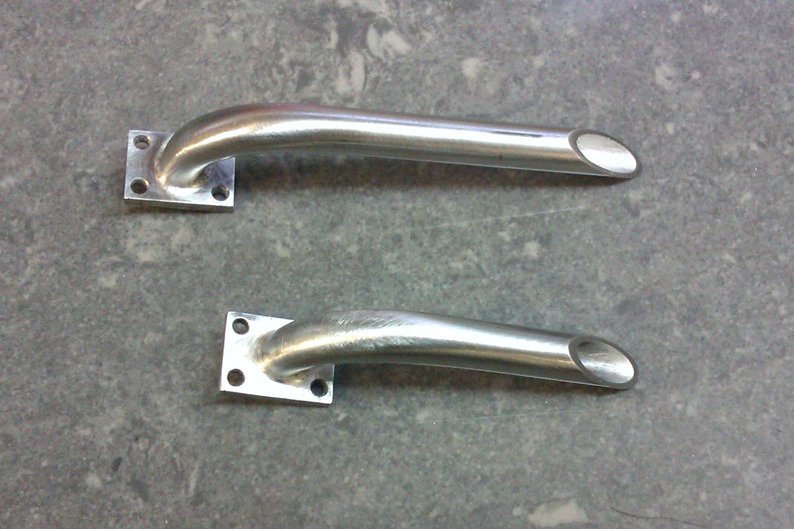
I suspect the jig was acting as a heat sink and drawing all the heat away from where it was needed.
This was the jig I used for the similar inlet pipes, 1/8" thick so it could be heated first and Tipex correction fluid used to stop any solder joining parts to the jig.
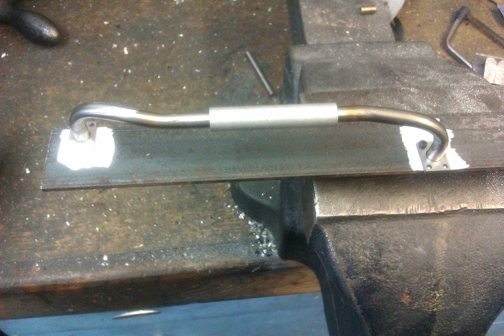

I suspect the jig was acting as a heat sink and drawing all the heat away from where it was needed.
This was the jig I used for the similar inlet pipes, 1/8" thick so it could be heated first and Tipex correction fluid used to stop any solder joining parts to the jig.

danallen
Well-Known Member
I agree with Jason. It looks like the joint was too cold when the solder was applied and it never flowed properly.
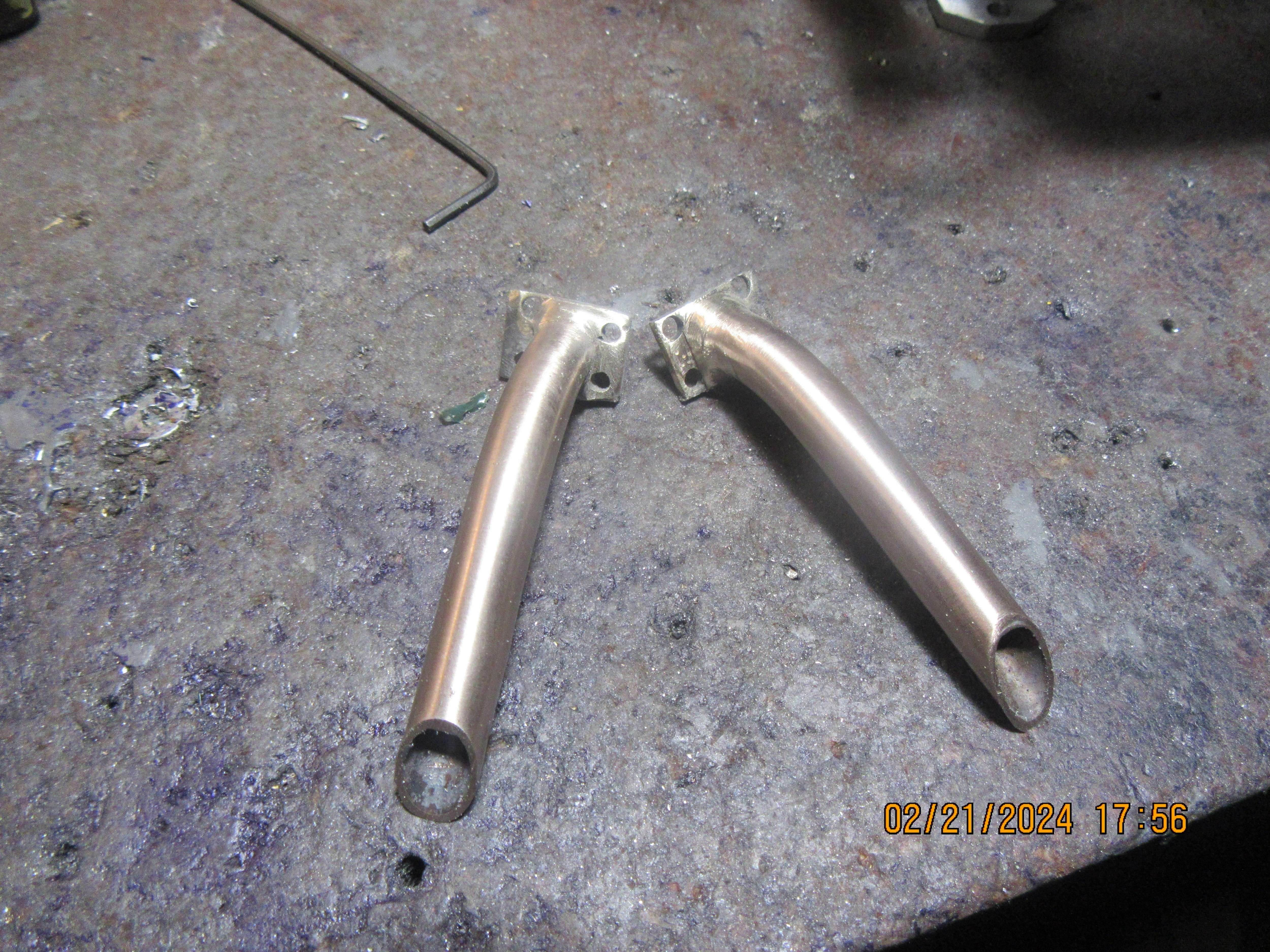
I set the parts up again using another simple jig, and resoldered them. This time the solder did flow the way I wanted it to. Not nearly as pretty as Jason's, but the job got done. There will be much filing and sanding, but the joint isn't going to fall apart.---Brian
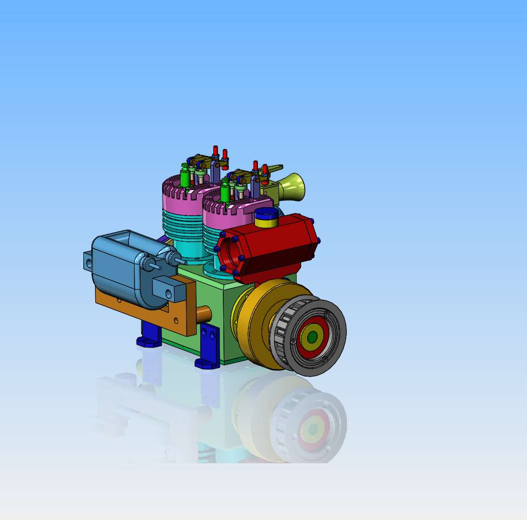
This morning I returned all of the snowmobile coils and got my $50 back from the used snowmobile place. I had mounted my old double ended coil from my twin opposed engine that I built ten years ago, because I know it works. I hadn't actually modelled it ten years ago, so I took an hour this afternoon and modelled the coil and bracket and installed them on my engine model.

I know they are not nearly as pretty as Jason's, but they are as finished as they are going to get. The second session of silver soldering went much better than the first. At least I'm sure they are not going to fall apart on the engine.

Similar threads
- Replies
- 118
- Views
- 8K
- Replies
- 25
- Views
- 3K


