Building a twin cylinder inline i.c. engine.

Home Model Engine Machinist Forum

Help Support Home Model Engine Machinist Forum:

This site may earn a commission from merchant affiliate links, including eBay, Amazon, and others.
Today was "little bits and pieces" day. I machined the four tappets, and between my shop and the main garage where my torches are, I lost two of them. Had to go back into the shop and machine two more of the darned things. Must have a hole in my hand!!! The tappets are heat treated, and the ignition cam is machined and in place, and I just picked up my sparkplug, condenser, and points from Partsource. I'm going to have to move up to a newer set of points, as the 1975 Chrysler points I have used for the last 13 years are now classed as antique and hard to get, and they cost $20 for a set. I had hoped to machine my valve cages today, but it's now 4:00 in the afternoon and I won't have time to finish them today.
WuD5PK.jpg
 
How does the piston look internally i.e. a full round hole or a slot in which the small end is attached? Can you show a CAD picture of your piston showing these details?
 
Today I installed the ignition points, machined the brass valve cages, and installed them. It's 2:00 in the afternoon now, and time to eat some lunch.
WYQGFe.jpg

g1J5pc.jpg
 
I'm thinking about possible gas tank shapes and location. I really like the gas tank built by Andrew Whale of the U.K. which has transparent ends built into the tank so you can see the fuel level. The perfect location would be between the coil output wires, but if I did that the tank could only be 1.5" long. If I locate it as shown in the model, I can make it 2 1/2" long, which suits me better. I can probably hang a mount and secure it to the gear cover. I'm not sure about this, but I modelled it just to see how it would look on the end of the engine. The only parameter that I have to meet is that the top of the gas tank can not be higher than the centerline of the carburetor.
bG8uMC.jpg
 
Hi Brian,
I would consider other constraints, such as the location of a cooling fan - and which way the hot air will blow? You don't want to boil petrol (about 100deg.F?) - or even just heat it, as a temperature rise from cold to hot could affect the mixture significantly. It has a large coefficient of expansion...
Equally, it does not want to become an earth for any sparks should there be any failure at the coils...?
What is your experience of your running times? Fuel capacity can be related to that? So if you do a few 5 to 10 minute runs, never more than 15 mins, then a 2 hour tank is not necessary. a 20 to 30 minute tank should suffice.
I have a Motorcycle that only does 100 miles on a tank-full. Around town and commuting 60 miles a week meant I only filled it weekly... so the small tank wasn't a problem. But maybe a smaller diameter and longer tank will give you options? I appreciate a larger flatter tank will give less variation of the petrol Head to the carburettor, than will a small and tall tank. A clear end is a very good idea. Use a petrol resistant gasket material. Glass microscope slides, or old GLASS spectacle lens can be cut/ground to function for that purpose. Or you can make a level gauge - like on a steam boiler? - That could be fun? But I am not sure how well the level can be seen with engine running vibration causing petrol to appear to "fizz"?
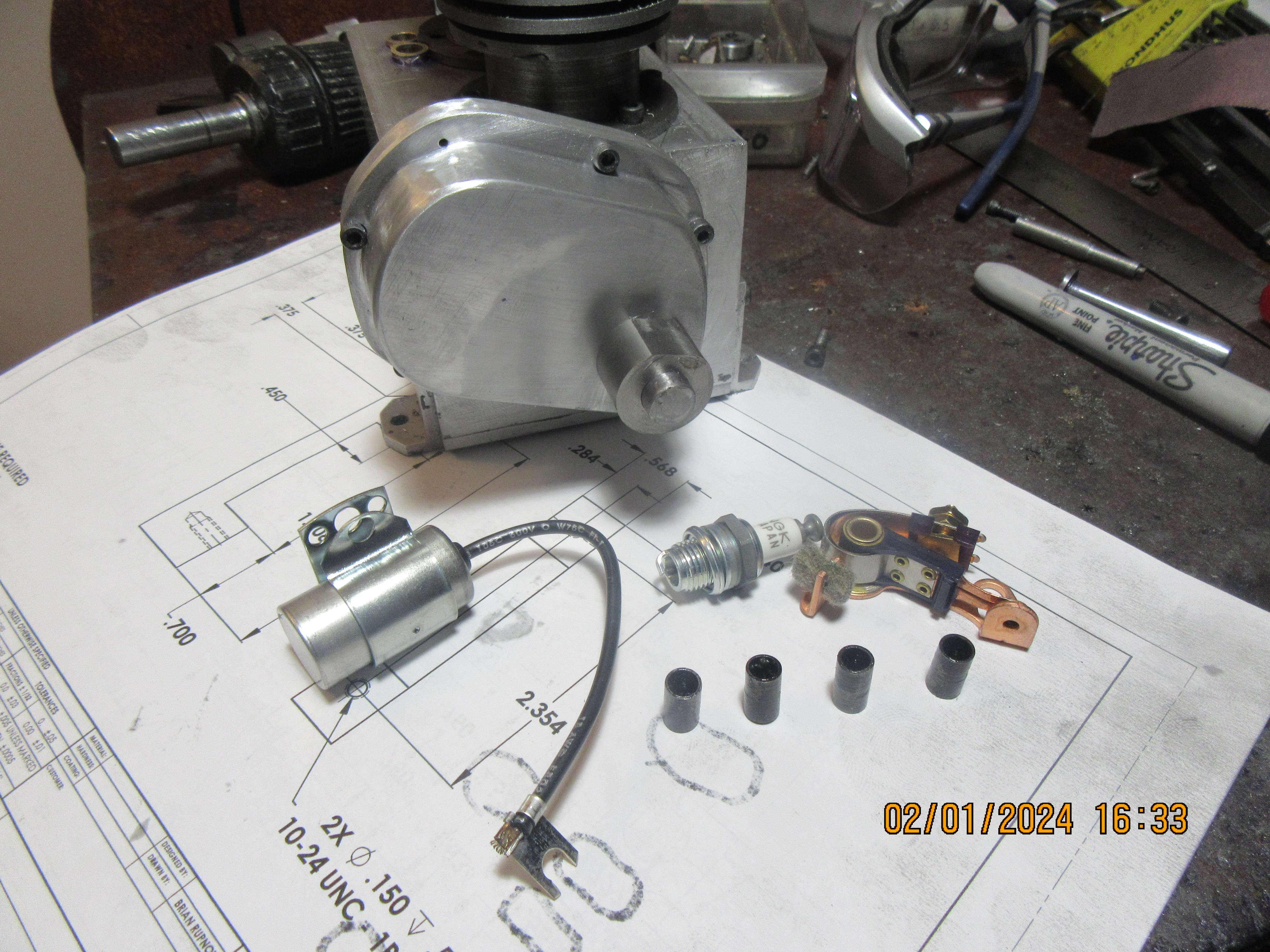
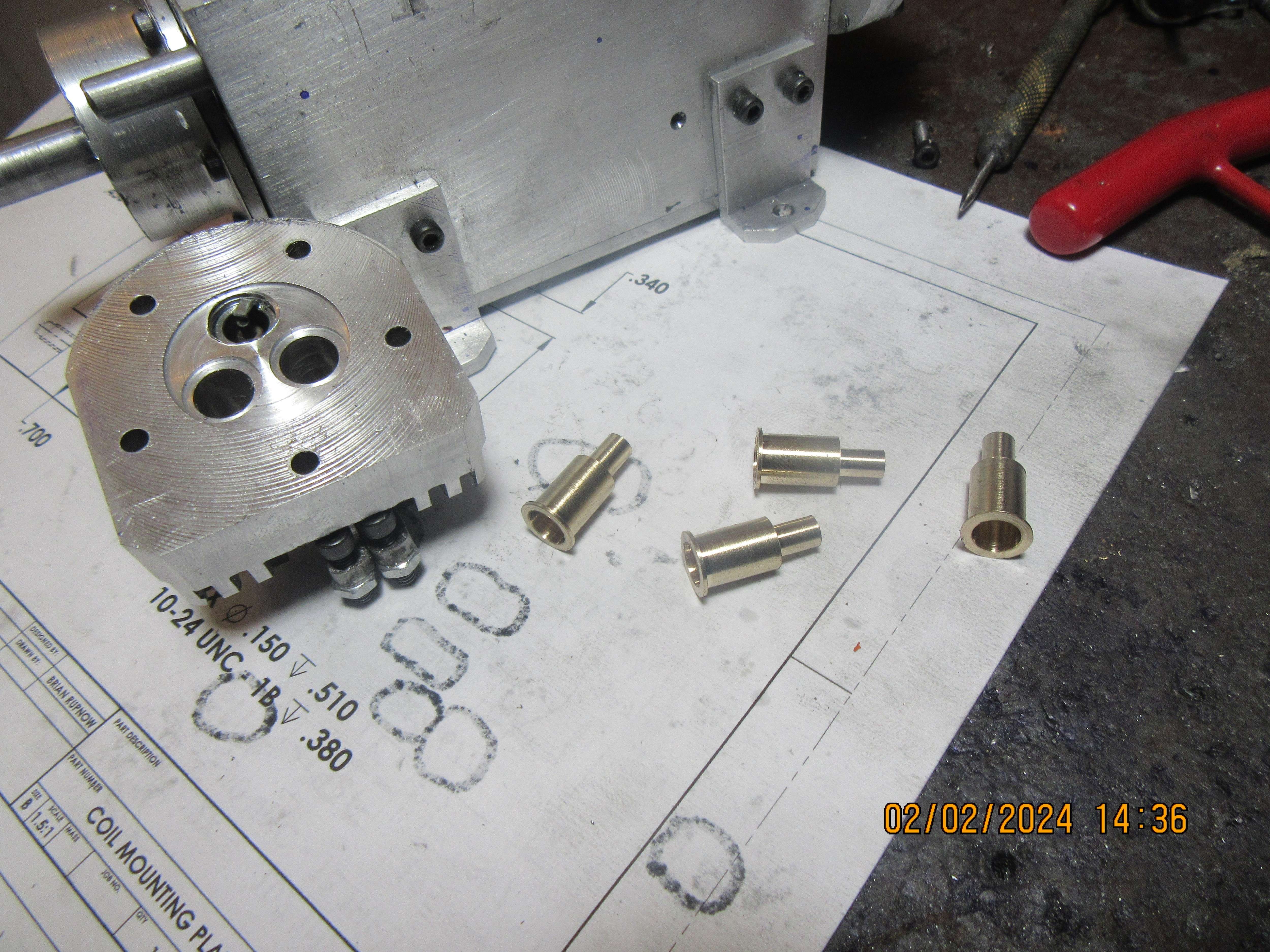
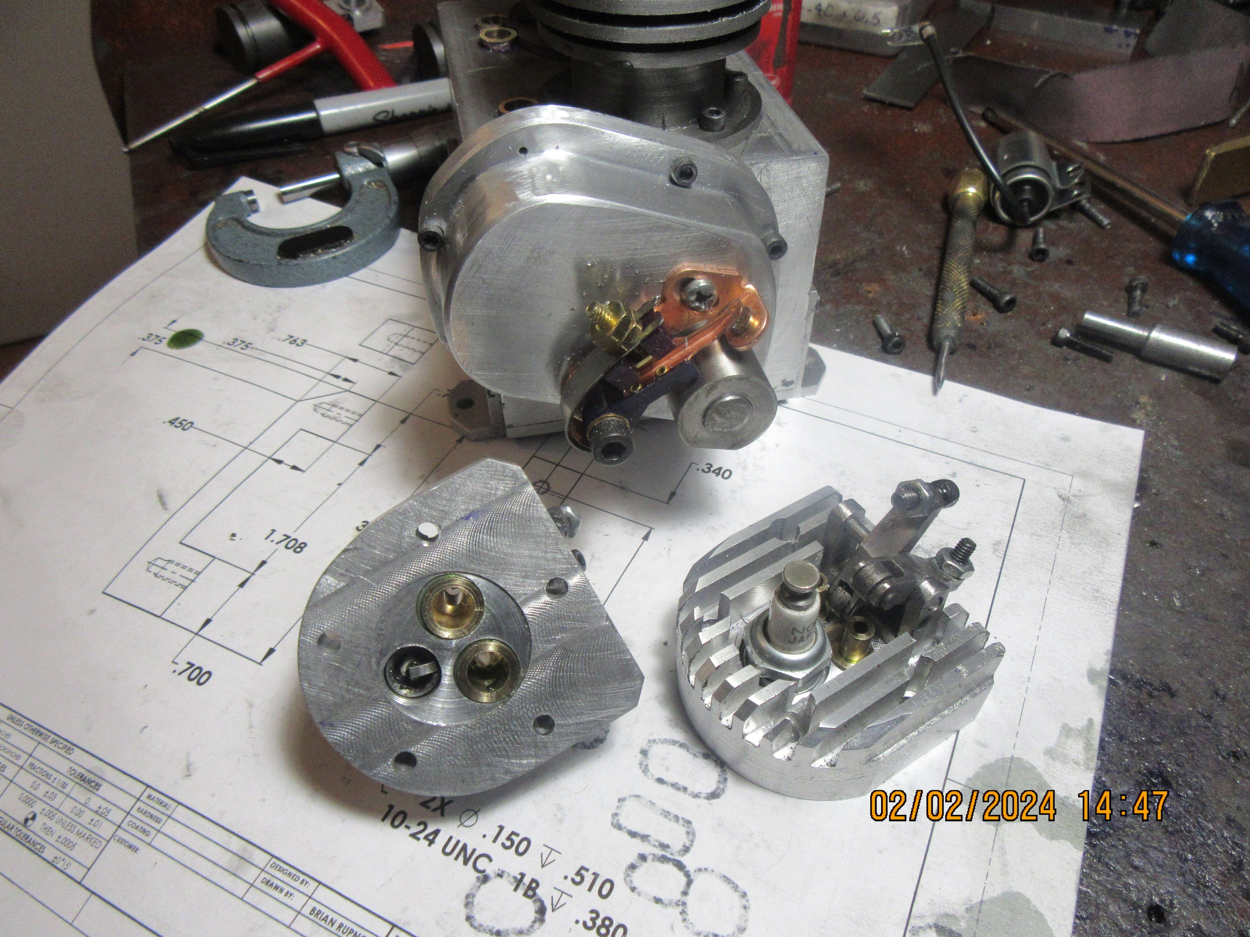
Love to see your photos. Excellent work.
K2
 
Not a lot of clever stuff done today. I did drill the intake and exhaust ports in my cylinder heads that intersect with the valve cages, and they all ended up in the correct place. I then made the flanges for my exhaust system, and Loctited them into the correct position on the cylinder heads. Tomorrow I will use a transfer punch to mark thru the holes in the flanges and then remove the flanges and drill/tap the heads for the #4 bolts that hold the flanges in place. The intake manifold spans between the two cylinders, so I probably will make the intake manifold and then reattach the cylinders to the crankcase before spotting the tapped holes for the intake manifold.
Jz8lJm.jpg
 
Today seen both cylinder heads drilled and tapped for the exhaust flanges, and both pistons were lapped into their cylinders. Cylinders were buffed up on a fine grit polishing wheel. I still have to put the o-ring groove into the top of the cylinders (they act as a head gasket), but I thought that I should wait until tomorrow to make sure Hercules o-rings actually make the size I want to use.
3IYCXZ.jpg
 
Today I machined an intake manifold. That doesn't sound like much, but I've used up almost half a day. The other half day was used up going to Hercules O-ring in Barrie and stocking up on Viton o-rings. The intake is just stuck in place with Loctite. Tomorrow I will transfer the holes to the cylinder heads and drill and tap the cylinder heads for #4-40 socket head cap screws.
lNURkg.jpg
 
Hi Brian,
I'm surprised to see a Brass intake manifold? - I thought Aluminium would have been in keeping with cost and aesthetics. But it was probably "what you had available"? - Usually my method of material selection if it suits..
And a bit of nice shiny brass always adds to a model... Like jewellery on a smart lady. You don't see the diamonds, just the sparkle in her eye. Yet the diamonds do add that something...
K2
 
I've made a mistake. When a cylinder has bolt holes in the top and bottom flange, it doesn't matter how exactly they are aligned if you are building a single cylinder engine. However, when you are building a twin, the orientation between those upper and lower bolt holes is critical. If you don't hold it perfectly, then the gap between the cylinder heads, which should be exactly parallel ends up being a quite noticeable angle. I've been able to correct things by slotting the holes a bit in the base flange of the cylinder, but it's cost me about 3 hours. Next time I put holes in a cylinder top and bottom flange, I will build a simple jig which holds the cylinder so that the bottom and top holes are perfectly angularly aligned.
UiH0Vx.jpg
 
A rabbit enters a bar and says "a small glass of whiskey, please"
Why for?
Because I need to gain enough courage to kill the wolf!
A fox enters the bar and says "3 small glasses of whiskey, please"
Why for?
Because I need to gain enough courage to kill the wolf!
A bear enters the bar and says "a bottle of whiskey, please"
Why for?
Because I miss the sparkle in my eyes!
 
Today the cylinder heads were drilled and tapped for the #4-40 bolts which hold the intake manifold in place and it was bolted to the main assembly. My next step is going to be making the valves, and I didn't have a good feeling about the length of the valves, so---today I did a layout showing the valves in both open and closed positions and I was right to do so. The original length was short by about 1/4". All is fixed now, and that will be tomorrows work, making four valves.
YTXq0d.jpg
 
It's been a very valvey morning around here. I have been under a time constraint, as I have to leave immediately after I post this to go for a blood test. I'm off to see the vampire!!!
TTxgXz.jpg
 
The valves have been lapped into their seats and had the shanks cut off after I lapped them. The valve spring retainers have been machined and fit the valve stems the way they are supposed to. The valves and their respective seats have been numbered so I don't mix them up as I proceed with the build. No valve springs have been installed yet.--Does anyone know where I can buy a small quantity of 600 grit lapping paste? Many years ago I bought three small jars of 320, 400, and 600 grit lapping paste from some guy who was buying large quantities and then repacking them into small jars about 2" diameter x 2" tall. I am just about out of the 600 grit paste.---Brian
oUyXZR.jpg
 
Back
Top