T head engine by Brian

Home Model Engine Machinist Forum

Help Support Home Model Engine Machinist Forum:

This site may earn a commission from merchant affiliate links, including eBay, Amazon, and others.
I spent the day working on a real job, but tonight I'm having a close look at this engine. I think that other than the flywheels and gear covers, everything is finished. I'm waiting for my cams to arrive, and there is a bit of finessing to connect the cams to the large gears. I don't need the gear covers to start the engine, so this could get exciting pretty soon. I'm still on the fence regarding the flywheels, but I want to go down to my nut and bolt store and look at something. They have a bin full of casters down there, and I remember seeing some large aluminum casters with rubber bonded to the outer rim. I have some double extra strong schedule 80 pipe here, and if I could machine the rubber off those aluminum casters and put some heavy wall pipe around the aluminum, it might make some nice flywheels.
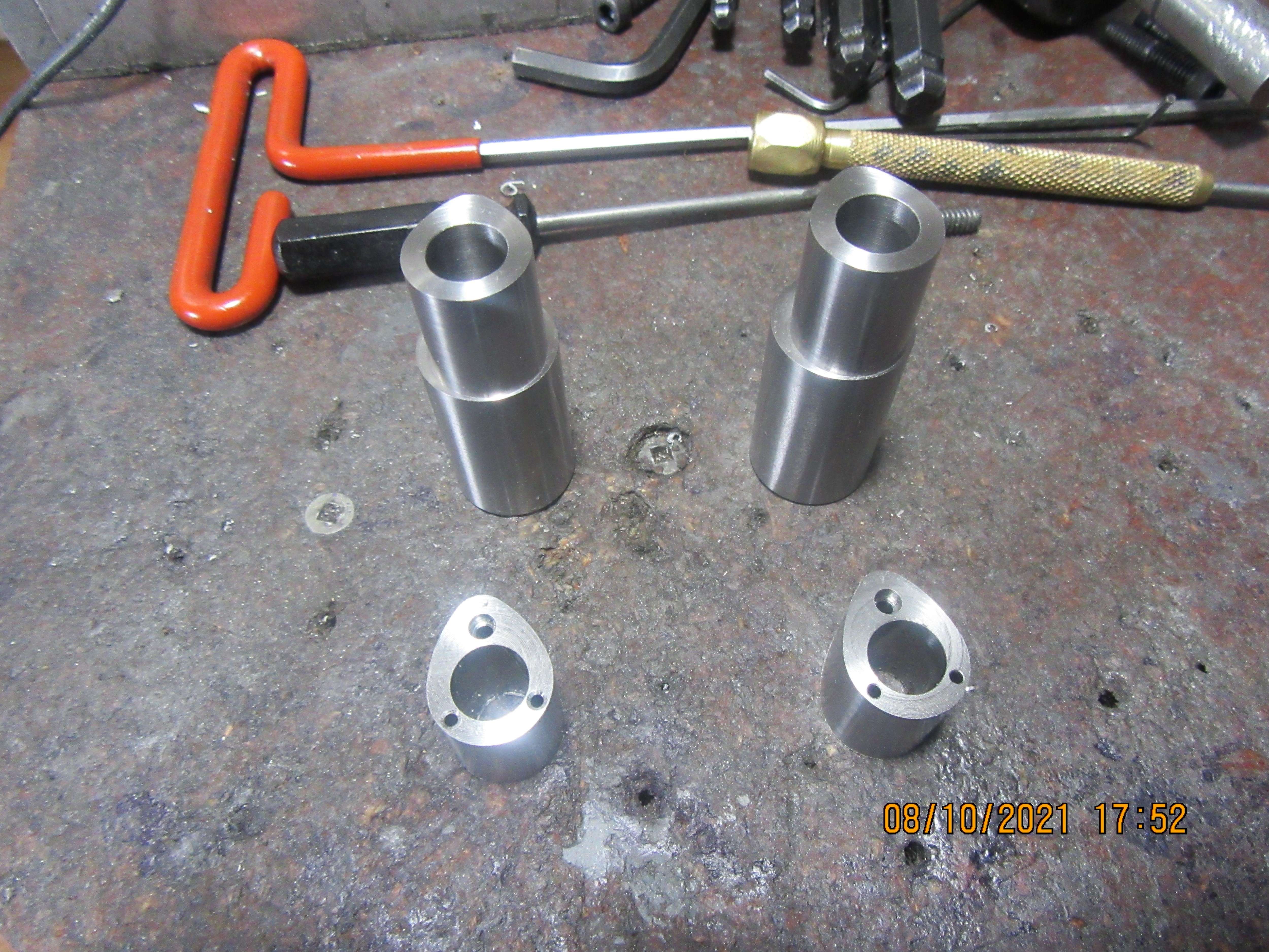
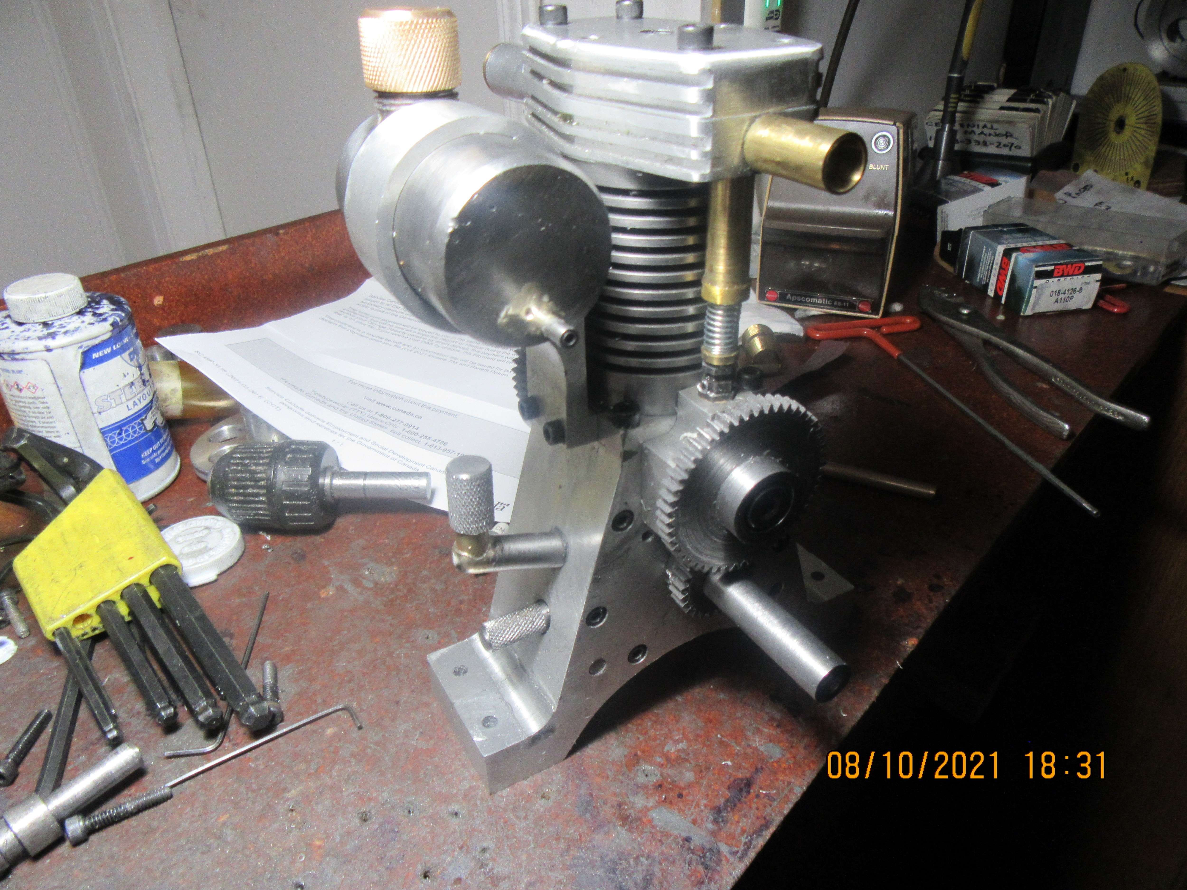
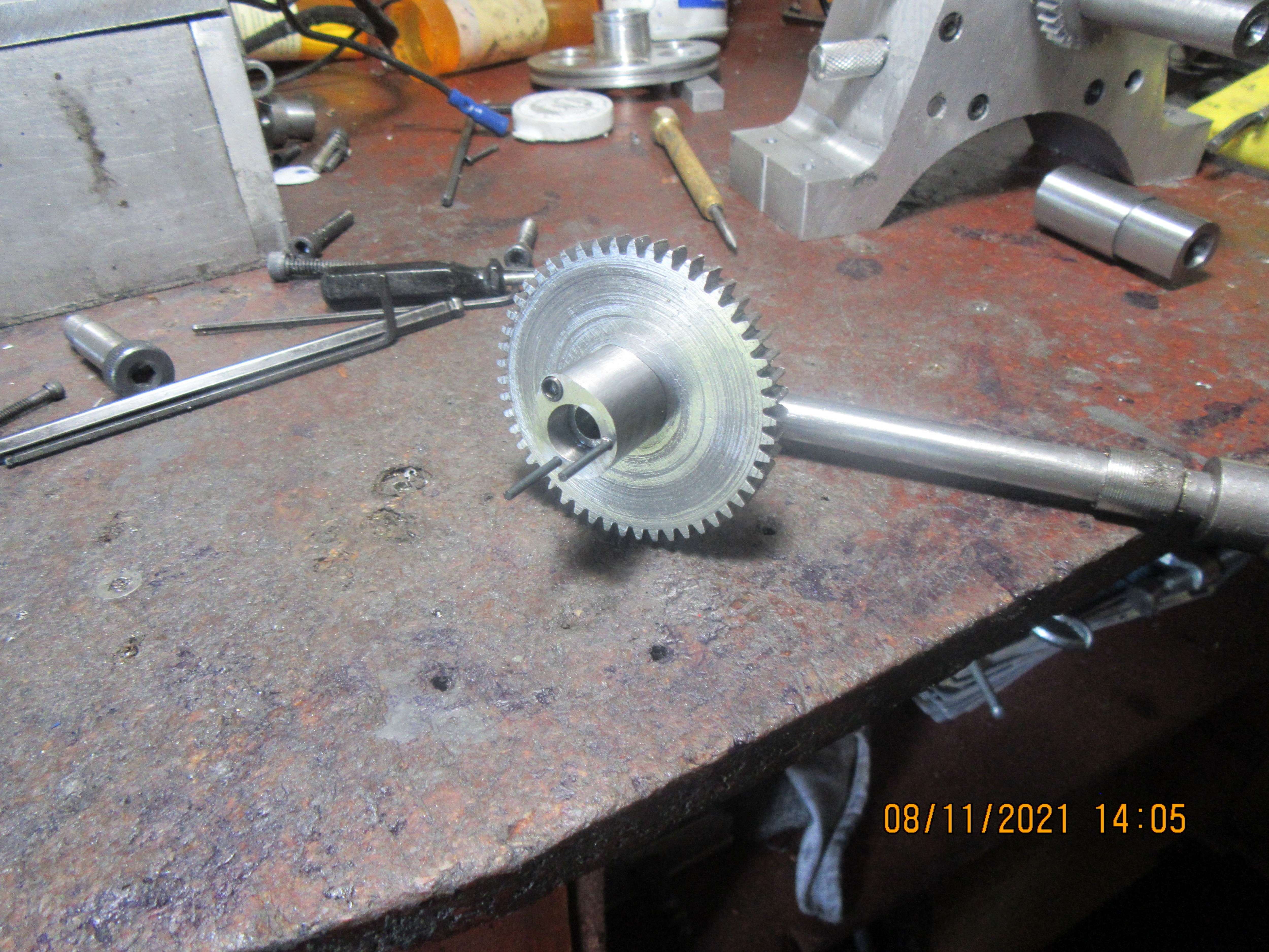
Brian, what diameter are the flywheels? I have some steel casters that I bought from Princess Auto that might work, 3" dia. with 1 1/2" flange and 4" dia. with 2" flange. I would give them to you but the postage might cost more than they are worth.
John Leeds
 

Attachments

  • image.jpeg
    image.jpeg
    164.2 KB · Views: 142
  • image.jpeg
    image.jpeg
    217.6 KB · Views: 154
How about this for iron casters to be used as flywheels? You get four for a somewhat reasonable price. You may have to do some work to disassemble and perhaps true up and balance, but it seems like a pretty good way to save time and get something that saves a bunch of time and money compared to making from a cast blank.
https://casterconnection.com/caster...-black-cast-iron-wheels-ccvintage-5s-set-of-4BTW - I can sympathize with you about being good looking but not rich. It is a curse a few of us are saddled with. I guess we all have our crosses to bear.
 
Last edited:
A HUGE Thank you going out to Sid from New York and to Laverne Karras from Keswick for the cams they CNC machined for me. Both sets arrived today in the mail, and they are simply marvelous. These cams are just about all I need to finish the t-head engine. Guys, I really do appreciate it.--I will use the cams Sid made on this current engine, and the ones Laverne made will be saved for my next engine.-Brian
OaICFC.jpg
 
Yes, even I get tied up with other things and machining has to take a back seat. I have however, found the time to make my oil filler spout and drain. It's pretty simple. You take both plugs out, and add oil to the sump until it starts to run out the bottom hole. When it does, then the oil is at the correct level.
gIOpWB.jpg
 
How about this for iron casters to be used as flywheels? You get four for a somewhat reasonable price. You may have to do some work to disassemble and perhaps true up and balance, but it seems like a pretty good way to save time and get something that saves a bunch of time and money compared to making from a cast blank.
https://casterconnection.com/caster...-black-cast-iron-wheels-ccvintage-5s-set-of-4BTW - I can sympathize with you about being good looking but not rich. It is a curse a few of us are saddled with. I guess we all have our crosses to bear.
That looks like a real interesting option for cast iron flywheels. Their comment “Each vintage caster is unique, with different details and may include intentional imperfections (i.e. nicks, scrapes, rust/corrosion, blemishes) for aesthetic purposes.” Makes me wonder how balanced they are and how true they will run “right out of the box” though.

Thanks for the link!
John W
 
Someone was asking how I would attach the cam to the large gear. Here it is. The # 4 socket head capscrew goes thru the cam and threads into a tapped hole in the gear. The two 1/16" drills which you can see will be replaced by 1/16" diameter drive pins, which pass thru zero clearance holes in the cam and the gear and are held in place by Loctite.
6UMHyE.jpg
 
G’day Brian, the TEE is looking great, so nice to see an unusual engine being made. Just thinking, In the video it looks like you have had to make a fair effort to turn it over? Is it very tight or does it just look like it?
 
I think that other than the flywheels and gear covers, everything is finished. I'm still on the fence regarding the flywheels, but I want to go down to my nut and bolt store and look at something. They have a bin full of casters down there, and I remember seeing some large aluminum casters with rubber bonded to the outer rim. I have some double extra strong schedule 80 pipe here, and if I could machine the rubber off those aluminum casters and put some heavy wall pipe around the aluminum, it might make some nice flywheels.
Hi Brian,
I bought a "flywheel" off e&@y... but it turned out to be either a wheel or maybe a well knocked around idler puller for a flat belt.... So for that engine I used a brass investment casting of a proper wheel "copied" from someone's machined flywheel of a Victorian pattern... You could see the original machining of the rim - until I did my own machining on it to look the part... It was well out of balance, but I secured it at the right place to almost exactly balance the engine (Double-acting steam table engine) - which now runs "very nicely, thankyou"..
So you can use out-of balance wheels to your advantage... with a bit of suck-it and see....
K2
 
Brand new engines are always a bit "stiff". After it runs for the first 15 minutes all of that stiffness goes away. Remember, when you machine something, although it looks very smooth, at a microscopic level the surface is all peaks and valleys. It's stiff right now because all of the sliding and rotating parts are riding on those microscopic peaks causing drag. After the first run, the tops wear off those microscopic peaks, and the engine becomes very smooth.
 
Well Rats!!! This morning I drove to everywhere in Barrie that sells casters, looking for a caster with an aluminum hub and flange with a cast in place outer sleeve of rubber or nylon. Princess Auto had exactly what I need, but not in the size I wanted. If I could have found the right size of caster I would have removed the outer nylon or rubber and mounted a steel outer rim to create "instant flywheel". Since I couldn't find what I wanted, I will now resort to making my own flywheels from what stock I have on hand.
 
I think the summer heat may have driven me mad. I just ordered a pair of 4 1/2" cast iron flywheels from Martin Models in the USA. I checked out what material I had to make these flywheels, and I do have it, but seem to be suffering from a case of "lazy ar$e". If I hadn't picked up the recent design contract for a couple of welding fixtures, I'd have made the flywheels from what stock I have. My good wife just informed me that any money coming from the small design contract should be spent on "Toys for my hobby" and I'm not going to argue with that!!--Brian
 
Thanks Mike

Divide by 5 "Doh" I must do some more practice with fractions !

Sadly my plates start at 15, which is infuriating. If I only had a thirteen.

according to the calculator 39 also works (it's 3 x 13) it gives 1 turn and 15 holes or 54 holes (3 x 18) and I do have a 39 hole plate.

Best Regards Mark
You need a hole plate that will divide evenly into 65, only 2 options that I see that is 65 hole plate or a 13 hole plate. With the 13 plate in will go into 65 5 times and 90/5 = 18 so with a 13 hole plate every 18 holes will result in 65 divisions. I am not sure how a 39 hole plate could work.
 
You need a hole plate that will divide evenly into 65, only 2 options that I see that is 65 hole plate or a 13 hole plate. With the 13 plate in will go into 65 5 times and 90/5 = 18 so with a 13 hole plate every 18 holes will result in 65 divisions. I am not sure how a 39 hole plate could work.
If you need a 13-hole plate but you only have a 39 hole plate, no problem - multiply the number of holes needed to move in the 13-hole plate by 3. Let's "unpack" the example above, assuming the worm gear ratio is 90:1 and you want to make a 65 tooth gear:

Turns of input handle per tooth = 90/65 = 1 & 25/65 = 1 & 5/13. (These are the numbers already shown above, but just showing a bit more of how they can be calculated - the general formula is [worm-gear-ratio] / [desired-number-of-divisions], then simplify the fraction. Look for an index wheel that has the denominator of the simplified fraction as a factor. In this case, 13 is a factor of 39, so we can use the 39 wheel.)

So the basic answer is, turn the handle 1 & 5/13 times per tooth ... but you don't have a 13 index, you have a 39 index. No problem: multiply the fraction by 3/3: 5/13 * 3/3 = 15/39. So now you have your final answer: set up the sector arms to allow a movement of 15 holes on the 39 hole index. (The sector arms will span a total of 16 holes - 1 for the pin to start in, and 15 more for it to move). For each tooth, make one complete revolution plus 15 holes as indicated by the sector arms, then reset the sector arms. Cut, rinse, repeat.
 
I am now at the "What do I do next" phase of this build. The only outstanding things are the flywheels, the gear cases and the rings and the gaskets. I don't really want to do anything on the cast iron rings until the flywheels have been machined and mounted. This leaves only the gear cases to be machined, so that is where I will start my next round of machining. the two gear cases will have a slight difference, because one has to be cut away on the bottom side to clear the ignition points. This will mean purchasing a foot of 2 1/2" x 1" aluminum flatbar. I'm beginning to get enquiries from old customers about design work. I don't really want to turn them down, because if it worked out right I might buy a real vertical metal cutting bandsaw. The saw I have now is an old wood cutting bandsaw that I modified to cut metal
 
I am now at the "What do I do next" phase of this build. The only outstanding things are the flywheels, the gear cases and the rings and the gaskets. I don't really want to do anything on the cast iron rings until the flywheels have been machined and mounted. This leaves only the gear cases to be machined, so that is where I will start my next round of machining. the two gear cases will have a slight difference, because one has to be cut away on the bottom side to clear the ignition points. This will mean purchasing a foot of 2 1/2" x 1" aluminum flatbar. I'm beginning to get enquiries from old customers about design work. I don't really want to turn them down, because if it worked out right I might buy a real vertical metal cutting bandsaw. The saw I have now is an old wood cutting bandsaw that I modified to cut metal
For gaskets I have been very glad that I purchased a Silhouette Plotter several years ago. There probably are other plotters which work as well. You make a DXF drawing and load it into the plotter. You usually have to do some minor rescaling. It makes everything precision and will cut out 1/16 dia clearance holes and weird configurations easy to accomplish.
 
Sorry if you covered this before, I am intrigued about the Silhouette Plotter
Did you get the 3 or 4 model and what material do you use for gaskets?
Thank you.
 
Back
Top