x2 belt drive pulley material

Home Model Engine Machinist Forum

Help Support Home Model Engine Machinist Forum:

This site may earn a commission from merchant affiliate links, including eBay, Amazon, and others.

keys

Active Member
Joined
Sep 24, 2009
Messages
41
Reaction score
0
I've been looking at the Jerry Rollet's Belt drive plans and I noticed he recommends Fortal 48,000 psi Aluminum. Most of my stock is 6061. Would 6061 be suitable for making the pulleys?
 
Mine are made from some scrounged up scrap-yard scraps. They're probably 6061 or 2024 and they are working fine. Not sure how long it'll take for a rubber belt to wear out a metal pulley but mine are going on about a year with no indication of wear.
 
Thanks for the reply. I made a replacement knob for my x1 mill out of aluminum. After any extended use, my fingers would turn black from using it. I'm wondering how long it would take the belt to wear through the pulley. Sounds like it would take quite a while.

Dustin


I have seen machine pulleys made of plastic and pot metal. My shaper is probably close to 60 years old and several pot metal parts the auto feed has been rebuilt. So I would say any machinable grade of ally 6061 should do fine.
Tin
 
I made mine out of 6061 2 years ago. No wear, the belt just keeps it shiny. :) The pulley will outlive the machine.
 
websterz said:
I made mine out of 6061 2 years ago. No wear, the belt just keeps it shiny. :) The pulley will outlive the machine.

Same here, although I cant remember when I made mine but the pulleys are as good today as they were when I made them and no noticeable belt wear either...Go for it, you wont be disappointed. :)
 
Thanks for the replys. I ordered a couple belts last week and I plan to start cutting parts soon. I wanted to start on the belt drive last weekend, but decided I should make a carriage stop for my lathe. I've been using the half a**sed, half nut, lock for a couple years now.

I'll be sure to post the adventures and progress of a novice.
 
Could someone tell me what the little diamond symbol means on these plans? For example, at the top of the page describing the pulleys it says,

3.10 " OD 38 <- insert little diamond symbol next to the 38

I have been searching all over the net, but can't find that symbol referenced.
 
The 38 signifies the included angle of 38 degrees for the belt profile....

You need to machine the belt groove to the dimensions given in the drawing...Set your top slide over to 19 degrees and machine the side of the groove...

I dont understand why Jerry chose to use 38 when the belt is 40 degrees...

Anyhow, thats the explanation for the 38 and the symbol......
 
John Rudd said:
I dont understand why Jerry chose to use 38 when the belt is 40 degrees...

Could it be because the radius the belt is going round causes the belt to be stretched at the outer edge (causing the it to become slightly thinner) and squished at the inner edge ( causing it to become slightly thicker ) , thereby changing the cross-section of the belt ?

( I dont have any evidence to back this theory up, it is just the mad ramblings of a semi-deranged mind that is starved of chocolate )

Tim
 
spuddevans said:
Could it be because the radius the belt is going round causes the belt to be stretched at the outer edge (causing the it to become slightly thinner) and squished at the inner edge ( causing it to become slightly thicker ) , thereby changing the cross-section of the belt ?


Tim

Tim your ramblings are correct...I read about this somewhere sometime ago and obviously forgot all about it...Thanks for the explantion ( again :) )
 
Thanks again for the help. I was wondering if that symbol was degrees, but I couldn't understand why they would switch to 34 and 32 degrees for the smaller pulley. I wonder if the decreased angle on the smaller pulley is to compensate for deflection of the belt, or to increase gripping force where there is a decrease in surface area?
 
keys said:
Thanks again for the help. I was wondering if that symbol was degrees, but I couldn't understand why they would switch to 34 and 32 degrees for the smaller pulley. I wonder if the decreased angle on the smaller pulley is to compensate for deflection of the belt, or to increase gripping force where there is a decrease in surface area?

Keys,

Dont sweat too much over the geometry of the grooves....My conversion is far from perfect and never been an issue as far as belt slippage is concerned...In fact a small amount is tolerable and better for the motor and electronics...

When a cutter becomes stalled, better for the belt to slip rather than relying on the electronics to cut in.....
 
I'm not really concerned so much as curious. ;D
 
I finally got going on this project. I imagine this is going to be a pretty slow project. My wife and I are expecting a little baby girl any day now so shop time is going to be hard to find. This is probably going to be boring to many. I'm writing this up for people who have a similar lack of experience.

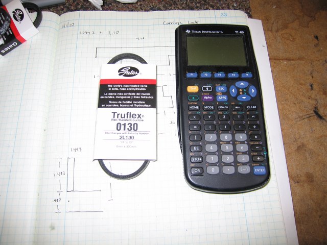
Last week I ordered the TRUFLEX 0130 belts from http://www.motionindustries.com/motion3/jsp/mii/index.html. They were much smaller than I imagined.
truflex0130.jpg

I bought three because I had to pay for shipping anyway. I figure a couple spares can't hurt. I might even find another use for one of them. I love it when I find what I need in my my own garage, and don't have to make a trip to the hardware store.


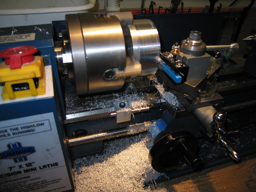
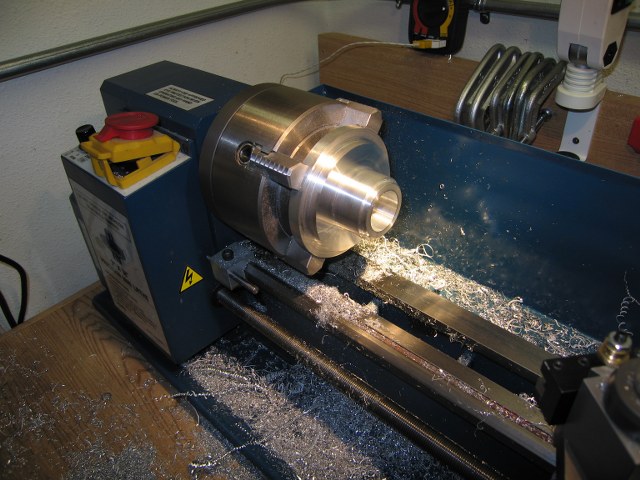
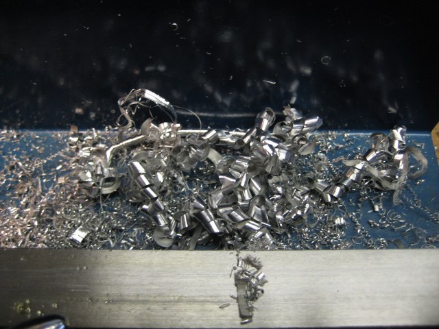
Earlier last week I chucked up a piece of 4in 6061 stock in the 4 jaw and started making chips. Actually, correct that, I started making awful noise, heat, and a poor finish.

cuttinglargepulley2.jpg


After making many adjustment, I was able to start cutting without chatter. I had to take .005 at a time running around 200 rpm. I was using a carbide tipped bit as my HSS tool would still chatter on these shallow cuts.

Once I knocked some of the diameter off I was able to use the HSS tool again. It's much more pleasant to use than the carbide tool.

hss.jpg


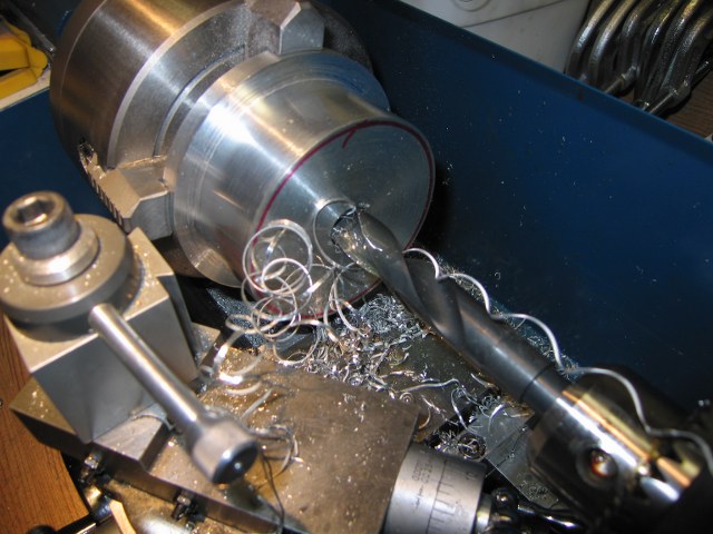
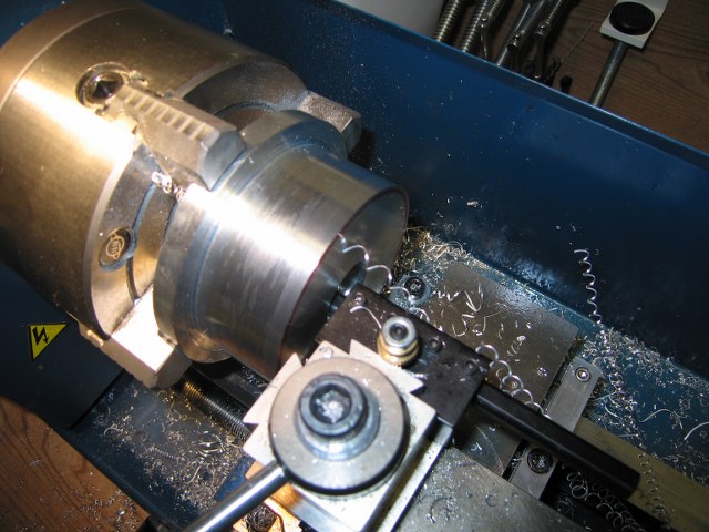
Here I'm drilling the hole for the boring tool. I drilled the hole out to 5/8th to give the boring bar plenty of clearance. I actually just stalled the lathe in this picture. Perfect time for a staged action shot. ;D

drill.jpg


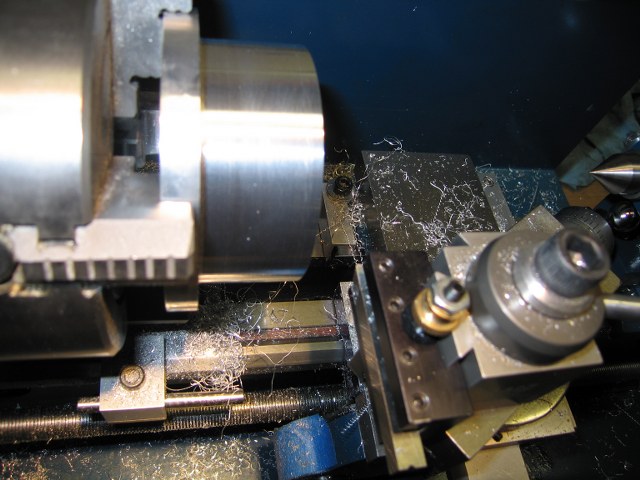
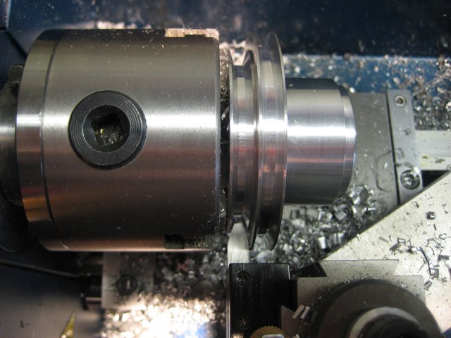
Here I'm wrapping up the boring operation. This is the first time I've used this boring bar. I bought one of those cheep import sets a while ago and struggled with it every time. I felt the cheap import sets bent too much. I couldn't see any flex at all from this bar. It made boring much more enjoyable. I highly recommend it for anyone struggling with the cheapo 9 piece import sets. Here is what I bought. http://www.littlemachineshop.com/products/product_view.php?ProductID=1780&category=-1134493617

boring.jpg


Well, time to get back to cutting.

Dustin


Made a bunch of chips yesterday. Here is the pulley still on the 4 jaw with one half turned to spec. My plan is to turn it around, and mount it on the three jaw to finish cutting the belt side of the pulley.

largepulley1.jpg


Here is the pulley, turned down and ready to cut the groves for the belt. I originally thought I'd be able to mount this in the chuck the other way, which left no room to cut the smaller diameter part of the pulley. Now that it's turned down to spec, I may try and flip it around. I don't really enjoy hanging a part this far out of the chuck.
largepulley2.jpg
 
I mounted mine on a mandrel turned up to fit the bore....
 
John Rudd said:
I mounted mine on a mandrel turned up to fit the bore....

Was it a press fit? How hard is it to remove after you are done? I might have to think about doing that.
 
Made a little progress today.

img_9826.jpg


I also borrowed my wife's camera which is taking much better pictures. To cut the grooves i ground up a 38 degree HSS blank. This cutting tool seemed to work very well on a slow speed and feed. I used my parting tool to bulk out some of the material. That lathe was pretty easy to stall using this tool and chatter was pretty bad at times. It reminded me of using my parting tool for the first time.

This tool created some of the cleanest shavings I have seen when the speed was just right.

shavings.jpg


Now I need to figure out how to cut the key-way. Any ideas?

 
The pulley blank was a relatively tight fit held in place with a 10mm bolt up the middle....

As for the keyway, I cut mine with a cutter( some 4mm HSS with a little clearance ground in) mounted in a tool holder and used the carriage of the lathe...Aluminium is fairly easy to cut using this method
 

Latest posts

Back
Top