William Fairbairn 10 hp.

Home Model Engine Machinist Forum

Help Support Home Model Engine Machinist Forum:

This site may earn a commission from merchant affiliate links, including eBay, Amazon, and others.

Maryak

Well-Known Member
Joined
Sep 12, 2008
Messages
4,990
Reaction score
77
Hi All,

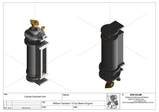
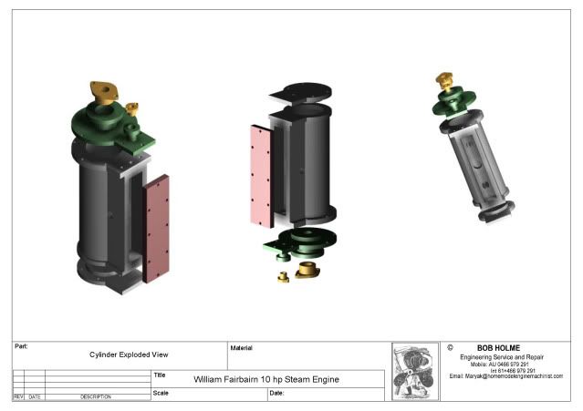
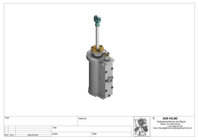
I came across the attached pdf in an old (1850's) book in a museum library some time ago. I had forgotten all about it until I started a bit of a clean out at home and found it in a pile of my old work papers.

I have started to scale it down as a model steam engine and as time and progress permit my intention is to develop a set of plans for a build.

Best Regards
Bob

View attachment FB10.pdf
 
Now that would make a nice looking model. Let us know how the scaling down goes. Thanks for posting this.
 
That is amazing how intricate things were made back then, now we have computers people arent as imaginative.
A .25 scale would be nice.
I hope to see the plans when you are finished.
-B-
 
Should build into a nice model though I think something like 1/12th scale 1" :ft would be better as it looks lik ethe flywheel scales out at around 10ft diameter, Unless you have a big lathe of course ::)

You can get a model of an almost identical engine, it's one of Anthony Mounts models and the build has beeen covered in Model Engineer

Jason
 
A beautiful specimen of the early engines used in the mid to late 1800's. Rather reminiscent of the Kendall Bros. "Williamson" engine that was offered up by Stuart several years ago. I like the idea of an outboard crankshaft support, it lends itself to a model that can perform some actual work by driving a pulley, or a gear as in that example.

BC1
Jim
 
Bob,
That would make a nice lookingi engine. I don't see any dimensions on the drawings though or am i missing them. How will you know what scale it actually is?

Bill
 
There is a very faint scale on the bottom of the second page

Jason
 
Ah ok....wow that is faint on the computer at least. Just missed it the first time looking. Thanks Jason

Bill
 
Wow,

August 2009 :-[ :-[ :-[

Life got in the way and now I am inspired by my recent TurboCAD course so I have made a start.

WFB10CylandCvrs2.jpg


Attached is a PDF of the Cylinder and I would appreciate a critique from any CAD gurus willing to pass on their expertise.

Best Regards
Bob

View attachment WFB110_1.pdf
 
Bob, the plans look great! Interesting engine, BTW.

The only thing I would change/adjust if it were me is how the construction lines (not sure what they are called in TC) are displayed. The lines over the renderings seem to be a distraction. I am unfamiliar with TurboCAD; sorry to be of no help! :(
 
Casey,

I agree the construction lines should not be there. I asked that they not be printed but damn and blast they appeared anyway. :mad:

I must have done something wrong. :eek: ::)

Best Regards
Bob
 
OK,

Got rid of the construction lines.......... turn of the layer and they're gone.

WFB10_2.jpg


I have just about 3D'd myself to destruction but I am impressed how great it is when you assemble things and the blunders hit you in the eye with bits too short or long or thin or fat. (Managed to make at least one boo boo on each axis).

I have also learned a great deal about how to correct all these errors in 3D. It was very intimidating at first.

In 2D delete a line or circle and problem solved. In 3D, slicing and adding/subtracting objects seems to fix things..............but I wonder.............is there a better way. ???

Attached is my latest offering for the cylinder.

View attachment WFB10_C_CC_GF.pdf
 
Nice bit of drawing, better than I could do.

One thing I did notice is that you have oval glands going into round bosses, it would be unlikely to have been made that way so either the bosses on the covers need shaping to match the glands or what was more likely is a round gland with three studs holding it down.

Also on the original section it looks like the cyl cover and the blad boss were separate items

J
 
Jason,

Thanks for the tips. :bow:

Which part do you mean - blad boss ???

Best Regards
Bob
 
Thats a spelling error, should have been bosses.

If you look at the section just above the letter "L" the cylinder cover and valve gland boss there is a vertical line which suggests they are separate pieces of metal. May make construction easier.

e-mail sent.

J
 
Don't forget your fillet radius on the inside corners of the cylinder flanges. The foudrymen would have insisted ;D


The first time I went 3D was a very frustrating experience as I "cut my teeth" on the drafting board and I came to realize that when I was thinking about design, I thought from "centerline out".

I found with 3D I needed to change my paradigm from that to the "outside in". This was a hugh stumbling block for me as I needed to reprogram the way I thought about a part. I succeeded eventually. I find it very helpful to take pencil to paper and sketch what it is I want first as it only takes a few minutes, focuses the task, and seperates the conceptual stuff from the mechanics of telling the software what it is I want. Makes for a less complicated thought process.

15 years later, I would never go back to 2D now...though I think about the boards occassionally with fond nostalgia.

You seem to be doing just fine Bob....I can assure you, I've "eaten the same dirt" and it's no fun doing it.

Dave
 
Dave,

Thanks for the support. :bow: The only thing I can fillet is fish ;D

OK, with help from Jason we progress a little more ;)

The assembly so far

WFB10Assembly.jpg


Attached are the drawings and sub assemblies as a PDF.

Best Regards
Bob

View attachment WFB10sofar.pdf
 
Bob, you are starting to scare me with the 3D CAD work! ;D

Looking great! :bow:
 
Casey and Jason

Thanks for the support :bow:

Jason provided me with a link which showed a variation on my engine using a parallel link motion instead of guides for the piston rod. One of the reasons for this was the difficulty of fitting the guides in a scale model. I am almost at the stage where this is going to be my problem with this engine. Rather than depart from my original 1850 plan, I am contemplating trying a split column design or a separate guide column inside the tapered Doric outer column.

Any suggestions advice etc. would be appreciated.

The devil is in the detail and my copies from the old book means the old devil is missing a lot of detail in this area.

My 1st attempt at the guides is attached

Best Regards
Bob

View attachment WFB10sofar.pdf
 
Will have a better look when I get in from work but did notice the holes in the top cyl cover don't match those in the cylinder. Glands look right now.

J
 
Back
Top