watercooled 50cc two-stroke.

Home Model Engine Machinist Forum

Help Support Home Model Engine Machinist Forum:

This site may earn a commission from merchant affiliate links, including eBay, Amazon, and others.

Owen_N

Well-Known Member
Joined
Dec 26, 2021
Messages
239
Reaction score
13
Location
Kawerau, New Zealand
This isn't a complete engine build, but will be a modified cylinder, plus various accessories.
I will move the Water brake build here, the exhaust chamber modifications, the electric starter installation, the fancy throttle lever, and all instrumentation.
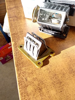
for the first build, I will start with a fairly standard cylinder, and add a reed valve housing for a 125cc reed valve, and modified manifold for a 34mm carburettor.
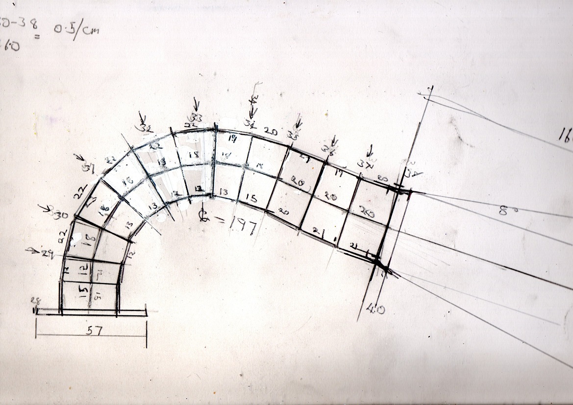
Here is the tapered lead-in pipe for the exhaust chamber.
It will be semi-segmented, with a fingered pattern joined along the outer curve, and brazed.
Here is the layout aside view of the pipe. Pattern will be in another post.
there is a slight swing-back in the curve, so I may have to split at that point and spin the tube pattern 180 degrees.
I have adjusted the segments to give smooth stepping between the rings.

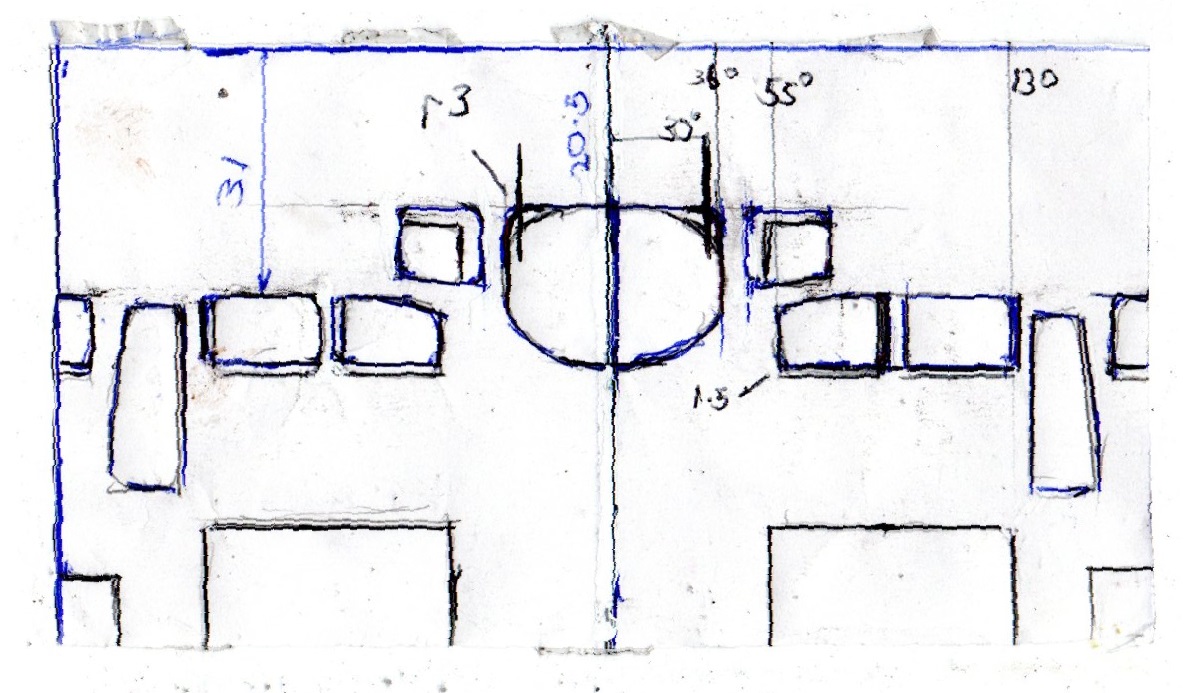
This is not the final layout, as I have to sort out the transition from a rectangular port to a round pipe.
If I follow the "wobbly" design, the rectangular portion extends out 1.5 times the bore (40mm) , and the transition takes 0.5x the bore, or 20mm.
This sounds rather short, so I will make the transition portion at least 30mm long.
 

Attachments

  • Segmented tapered  exhaust bend 10-06-22.jpg
    Segmented tapered exhaust bend 10-06-22.jpg
    297 KB · Views: 49
If you are interested in 3D modeling the details if a two stroke cylinder I have the method I use explained below. The example is for a piston port engine, but similar methods can be used for any design. The solid passages can then be cut into a solid that represents the cylinder. You will need to be familiar with a high end program like Fusion 360 or Solidworks. It still takes a lot of work and patience.

Lohring Miller
 

Attachments

  • 3D Engine Modeling.pdf
    960.2 KB · Views: 138
If you are interested in 3D modeling the details if a two stroke cylinder I have the method I use explained below. The example is for a piston port engine, but similar methods can be used for any design. The solid passages can then be cut into a solid that represents the cylinder. You will need to be familiar with a high end program like Fusion 360 or Solidworks. It still takes a lot of work and patience.

Lohring Miller
I will not get into 3D modelling for now. It looks like a practical fabrication method is metal 3D printing with laser sintering,
which would require 3D modelling. Cumulative costs of casting and making lots of bad casts make this attractive.
However, I would like to try a tig welding approach to start with.
I can re-use the upper outer part of the water jacket if I use a wet sleeve and weld to seal at the exhaust port level.

Getting material sources is a problem. Do I need high silicon alloys, or can I use 6063 or similar for the barrel, and Nicasil it?
what would be temperature and time to stress relieve it? would it be strong enough.]

Suppliers are reluctant to provide small quantities of, say , Lm6 casting alloy in machinable shapes. Could I just buy an ingot and carve it up?
would it be too porous for machining?

The current performance standard is an RVRT Zundapp, which is not a sophisticated engine - it looks to be reed valve, single exhaust port.
This means that a fancy barrel may not be necessary for good 17,000 rpm performance. It is mostly in the pipe?

I am looking at a 34mm carb and a good 125cc reed valve. This will require severe mods to the cases. The engine should tolerate a fairly low crank-case compression ratio. I am not sure what the exhaust timing should be, so I will see what in comes with. I guess about 180 degrees duration. I can measure it up, and do a simulation.

Further to the Water brake design, a water flow rate of at least 3.4 L/m is needed to avoid 100 degree C internal water.
This sounds like I should connect it to a mains pressure water hose, and discard the hot water. Can I control this closely enough
with a pair of 1/2" globe valves? for this low a water flow at high pressure, it may need a 1/8" (3mm) globe valve.
I will look one up. The 1/2 inch should be ok for outlet flow. The engine is likely to be used for 5 minutes at a time.
 
Alternative inlet boost system:
If it turns out that bypassing the reed valves at around the effective rpm range of the pipe, is a good thing, then the leaves in the reed valve can be propped open by a central blade in each reed opening.
This could be activated by a moving cylinder outside the carb bore size, if I stand the carb off a few more cms.
There is more than enough flow area in the large-sized reed valve block.
It is worth a shot, if it appears that the reed valves are limiting performance.
The pipe should have enough vacuum to keep inlet flow going.
Would there be a problem with any flow reversal out the carb?
Could this be countered by lower crankcase CR and a longer inlet manifold?

The advantage of this approach is compactness, instead of having two inlet tracts.
 
Corrections for the RVRT Zundapp, by Rob Van Rossem.
The one that did 24.6 ps (pk) at the rear wheel was a rotary inlet valve engine, and the Malossi RVRT barrel has secondary exhaust ports which are sharply angled into the main port. There is probably not enough material to do this on the KTM barrel (2005 pattern.)
 
I have had a look at some of this. I am intrigued by the 2-layer exhaust and transfer setup that Frits- I think- is suggesting.
I have the Janbros pdf and spreadsheet, as well as engmod2T. I had a further look at the KTM50 LC engine, and it is very similar to the RVRT port setup, so the barrel probably won't need big changes to make good numbers. I will see if I can get it to run properly at 15,000 rpm, then work up from there. I will have a closer look at the other parts. Seeing as I haven't got a disc valve kit, I will look at the option of propping the reed valve at around the pipe speed.

From Rob van Rossem's results, it looks like a full "wobbly" exhaust manifold is not really required, and side ports don't need to breathe that well. They are just there to improve the initial "Puff" width. The rectangular-to-round transition can be moved out about 60mm still, and be spread over 30mm, to 30mm exhaust internal diameter at this point.
However, the later model KTM barrel is closer to a Wobbly layout, so it must offer some advantages. 24.8 ps is not too bad at the rear wheel.
I thought the general aim was 30hp at the crank? He has probably surpassed this by now.

The next job I have to do is pull everything off the ends of the crankshaft, and set up a sensor for running the engine the other way.
I think the thrust face should be on the cool side. I have founds the piston snags the exhaust port if I run the other way, and scrapes the top land. I probably cannot use the existing magneto for this.

It looks like it uses multi-hole pullers to get the parts off.
What is a good advance? - I was thinking 15 degrees advance basic, but a fully programmable ignition system would be good, like Alex on "2Stroke-stuffing". He has a lot of good gear!
 
Ideas for grafting on new partial exhaust manifolds:

If I can find mating surfaces 5mm wide, and enough depth to take an m4 screw, I can bolt up form-fitting aluminium blocks,
and seal both the water-jacket and the exhaust with silicone gasket sealer. If the gap is under 0.5mm, the sealant should stay put.
I will check this out. I think the blocks will fit above the front retaining nuts.

The water entry into the jacket may need some changes, as it is very close to the exhaust channel.
I will have a go prepping the surfaces to take 10mm thick blocks. This may be enough.
If I leave enough material and block surface, I could bolt up another layer.

The idea is to improve gas exit from the secondary ports, and blend it in slower, via a bolt-on manifold extension.

Further seal improvement could be grooving to take a harder silicone round strip.
If the edges are under 5mm, I will need to look at other sealing options.

A possible method is to get a gas heating ring, so I can heat the whole barrel up around 380-400 degrees c.
I will see if I can get a thermal crayon for this.

Then I can use the aluminium brazing/ soldering rods to build up the edge material. That stuff is strong enough to take a thread.
The coolant keeps the area at a low enough temperature, so it will not melt again.

I can use stainless steel as a former, as the molten material does not stick to stainless.
From the on-line demonstrations, the material has good adhesion to the base aluminium.
 
Last edited:
The engine has arrived!

However, it seems to be about 63 cc one, not 50cc.
This is probably not a problem, as I can factor down the power to the 50cc standard.
50 cc is 79% of 63cc , so the 30hp aim rises to 37.8 hp.

I don't know what hp standards everyone is using, Dutch appears to be ps or pk, or 736 w, and imp hp = 745 w
the 44.85 bore by 40.0 stroke is not ideal, though. square bore and stroke give best transfer area.

The barrel seems to have enough wall thickness for quite a bit of secondary port shaping, so I will try that.
There is no cooling of the exhaust ports, which affects power.

The engine needs to be spun the other way, so I will need an electric pump. The existing pump is the wrong handedness.
A degree wheel and a spark flash torch will be needed. I don't know how this drives off the existing ignition. - wire coil pickup on the spark lead? There doesn't seem to be a separate trigger, just 2 magnets. Presumably one magnet edge is used as a trigger?
There are 2 identical poles at 180 degrees. I will see if it fires in reverse.

The exhaust port only spans 65 degrees, and has very round corners. This can be squared up to 3mm radius corners, if the engine goes the other way.
I think the shape is to reduce scraping on the top ring land in reverse running.
65 degrees is the limit for straight ports with small radii.
Exhausts usually go up to 75 degrees with large radius corners and a curved top.

I can also line up the exhaust port tops to get better blowdown. I can reduce the exhaust bridges a bit, and transfer bridges can go down a bit in width.
I think bigger side ports and smaller main port is better, for good pipe action, as the top edge can be straighter.
If you want to widen the power band, possibly a curved top and lower side ports is is better.
I won't bother with a wide power band for now.

There are 3 boost ports, but 2 have a lot less timing. The "B" ports seem to be higher than the "A" ports.
The ring gap passes over the center boost port. I will do a port print, and run it through the engmod2 simulator.
All the ports need a tidy up,

The port floors need to be lifted a little, with J_B Weld, to line up with the piston at bdc.

The "A" port angling seems a little bit low. I will check it out.
I am planning on changing the shape of the reed valve housing, which means there will be one less case bolt.
I will give it a go, as there are quite a few case bolts, and the case should be stiff enough.
Another case bolt could be inserted above the reed block housing, and below the barrel mounting deck. It would need to clear the barrel studs.

The top of the rear "gearbox" area needs to be removed for room, and possibly the top rear engine mount. This will be a bench engine, so I can work around this.
When the new reed block arrives, I will draw up a bypass mod that ports through the center of the "W" reed layout.

This engine only really needs the outer reeds, anyway. A possible problem is that this will really screw up the carb mixture,
requiring a fuel injection system, but I will try with a carb first. Many of these race engines use an electric "power" jet at full throttle.
 
Start of engine mods:

I have done these barrel porting changes.
The double line show old and new port edges.
Basically a bit of a blueprint job. Transfer ports flow limits may be raised by a couple of percent.
If the simulation suggests it, I can make the secondary boost ports deeper and less of an angle.
The top edge of the "A" transfers needs to be filled in a bit with J-B Weld to get to 25 degrees.

I have deepened the front pockets for the "A" transfers to adjust the aim point just past the center of the piston.
The passages for the side exhaust ports are straightened and opened out a lot.

The side exhaust bridges look a bit feeble, and hopefully they don't give trouble.

I have left a slight top curve on the main exhaust port, and checked that the exhaust ports all open within about 0.1mm of each other.
These changes should really improve blowdown.

The port timing is 86 degrees exhaust and 118 degrees transfers from top dead center, making duration 188 degrees exhaust, 124 degrees transfers.
Blowdown degrees is 32 degrees.

Next job. - Add a 15mm exhaust spacer, with a slight oval to round transition, and neck down to 24mm.
currently it is 26mm x 28mm.
The port roof is a little high at the existing outlet.
This gives a step back up to 26mm in the exhaust stub, and the stub outside is 31.5mm. The header pipe will start at this size, and increase to 38 or so mm over about 140mm length.
This restriction and step is favoured by good engine tuners. It helps keep bounce-back mixture a bit cooler.
 

Attachments

  • Port map 63 cc engine 25-06-22.jpg
    Port map 63 cc engine 25-06-22.jpg
    221.1 KB · Views: 44
Reed valve assembly with bypass:

This is based on the 125 Yamaha reed valve block.
It is further spaced out to fit a 30mm butterfly valve in the middle, and the centre petals are removed.

The objective is to discard crankcase compression once the engine gets on the pipe. The pipe suction is capable of doing all the transfer breathing beyond this point.
Crankcase compression ratio may decide whether this will work well. If the ratio is about 1.2:1, mixture reverse flow will be quite low at higher
rpm.
Reverse flow is undesirable in that it richens the mixture and messes up the carb settings.
The shape of this outlet end will work like a tesla flow diode, to reduce back flow from the crankcase.

In the extreme case, if you get the induction length wrong on a piston-port engine, it can
fill the whole garage with fuel-air mist, whish is really undesirable.

The reeds are quite stiff, and restrict flow, so a bypass should improve breathing. There is enough crankcase suction to get the engine up to speed with the reeds

Alex from "2stroke stuffing" has shown that this seems to work in practice.

Another possible addon is to fit an extra 100 cc or so of extra volume in a cannister that opens at the same time as the centre butterfly,
to further drop the crankcase CR.

Carburettor size is a questionable subject.
Many people get good results with a 28mm, which is a restriction in the race class, but Alex has shown that a 33mm bore works well. I will try with the 34mm, and can downsize to the 30 if the big carb goes flat when I open the throttle.
 

Attachments

  • Reed valve with bypass 29-06-22.jpg
    Reed valve with bypass 29-06-22.jpg
    210.6 KB · Views: 33
Last edited:
Latest progress on engine and addon parts: 05-07-22

The engine is now fully dismantled. It looks like there is a rear inlet passage over the flywheels and under the barrel bottom.
This means the valve block would be better twisted 90 degrees from where I was originally planning, with the bypass butterfly shaft sticking out the side. The valve block needs to be pulled back another 25mm, which increases crankcase volume by roughly 25 x 50 x 40mm, or 50 x 10**3 ; 1 cc = 10**3 cu mm so we gain another 50cc . I assume the crankcase volume is already about 200 cc, and I can accept 300cc crankcase volume in total. The window area is about 20 x 50, so the 25mm adapter needs to contract the bottom side in and turn the center channel a bit.
This means half of the reed valve will not be as effective, but it is not needed to spin the engine up to 9,000 rpm to start getting on the pipe, when the open center channel can then be used.

I am also cutting the backs out of the transfer channels, giving 4 holes 12x12mm, which allows be to use my existing tools to tidy up the J-B Weld filler in the transfer ports. The alternative is to buy $800 US worth of special right-angle porting tool. I haven't seen anything else that compact and robust online. Dental tools self-destruct quickly.
I can easily block the holes up again later, and plaster the inside again, where the surface is reachable with my tools.

The bridge between transfers and side exhaust ports is a bit rough, but it should still work if there are no huge gouges in it.
There is a potential for short-circuiting transfer mixture out the exhaust, and this does happen if the piston pin cutout passes over both ports ,
but a tiny gap above the transfer is less leaky.
The vertical bridges next to the exhaust need to be fairly smooth and hard, as they are actively supporting the piston ring.

I am working on the transfer port floors with a spare piston glued in place, and I notices the secondary rear boost ports seem to be very small and low.
I will keep the rounded shape, but lift the tops up a bit. I assume they were lowered to stabilise the rising scavenge jet column.
I have re-directed the "A" ports back to where they should point, so this should help push the rising column back a bit.
The "A" ports need 25 degrees rise, and the leading edges should be pointed past the center of the piston. This may have been a feature that was lost in copying the original design.

I noticed that:
1) it has the wrong sparkplug- too short.
2) the engine has not been trial run. When you get a model airplane engine, they have been test-run.
3) the compression ring looks suspicious, with scoring next to the gap. I will try it, and see if it works.
4) The inside of the engine and gear area had a lot of particle residue in it- this should have been well cleaned!
I suppose the original centrifugal clutch would deposit plenty of particles in there after a while, though.

I have bought an electric water pump, so I can run the engine in the conventional direction.

I have a starter mechanism intended for a model aeroplane engine of the same cc rating, and it has a magnetic trigger on it, so I can use this to run the ignition. I can adapt the correct sensor, and one of my 6V ignition modules, though the lead, cap, and ground will need to be swapped. I wonder if I can run this through the rubber- dog shaft coupler -this shouldn't affect timing much, though the brake will load up the coupler a fair bit. This should make enough spark. I have an ignition timing flash gun, and have a degree wheel on order.
Roughly 15 degrees should do as a starting point. The CDI module has a startup retarder built in.
 
Update on Two stroke mods:

Development of the combined reed valve with bypass.

The core device has been completed. I am now working on the clamping plates and the carburettor adapter.
Photos to follow.

It occurs to me that I can eliminate the bottom reed valve set for very little breathing loss at 9,000 rpm.
I will try with and without.
Eliminating this area also stops fuel pooling when the bypass is used.

I am drawing the adapter more round to rectangular to use available breathing cross-section area.
The cases have been cut away for clearance, and I can build them back up in aluminium and J_B Weld. Everything seems to fit OK.

Reviewing the project, it will take me a while to get to first run- maybe another 6 months? Most materials are now on hand.
I will have a bit of trouble clearing the chips out of the crankshaft bearings- compressed air would be handy, and I can't get them out without needing a new set of seals. We shall see.

I need to set up an alignment check rig for the crankshaft, too. I have a dial gauge probe, and tons of ballraces. The level of finish does not look so good, and I cannot just check flywheel alignment with straight edges.
Just measuring across the machined outer faces of the flywheels, there is 0.1 mm difference in spacing close and furthest from the crankpin, which seems rather a lot! you would think they could get squareness better than that!
There is also the use of steel rivetted caged bearings, which tuners avoid. Again, we shall see how long everything lasts. I need to get set up to dismantle and re-assemble the crank.

There are a few minor air gaps here and there in the reed block core assembly,( center butterfly and reed to cage) but I think they are pretty small compared with the cross-section area and the airflow expected- in the order of 25 m/s???
I will try bonding the air trumpet adapter with J-B Weld to start with, with little overlap tabs. I can rebuild it later with brazing if it shakes to pieces with the vibration.

Here is an updated drawing of the reed device, with actual dimensions used:
 

Attachments

  • Reed valve with bypass developed- 31-07-22.jpg
    Reed valve with bypass developed- 31-07-22.jpg
    315.6 KB · Views: 2
Photos of the reed block with bypass:

This is probably easier to make out than the drawing.
The other reed block is the original. I may use half of this with the butterfly valve, as the reeds in the carbon fibre unit seem to be much stiffer, and may not work as well.
The idea of the reed valves is to make starting and initial run-up work more easily. Once on the pipe, crankcase compression is not important.

I can tell if it is working if it doesn't fill my garage with fuel mist, and the torque picks up when the bypass is opened.
Some experimentation with lead-in piping and crank-case volume may be needed.
Initially, a rope drag with a spring can be used, and I can manually open the valve. The actuator disc is shaped like a V pulley, so a rope drag will work.

These tuned engines seem to have chronic mixture problems on and off the pipe, so many tuners have switched to injection, with the injectors shooting into the "B" transfer ports. The "A" ports are closest to the exhaust.
Climbing on the pipe, and part-throttle running on the pipe, seem to be problem areas. Some have added an extra top-end "power jet", electrically activated. Part-throttle seems to be prone to detonation,
which is not present at full throttle.
This engine, as a bench engine only, should be less of a problem, as these flaws tend to show up in track racing.
 

Attachments

  • IMG_20220804_1.jpg
    IMG_20220804_1.jpg
    44.5 KB · Views: 3
  • IMG_20220804_2.jpg
    IMG_20220804_2.jpg
    52.6 KB · Views: 1
  • IMG_20220804_3.jpg
    IMG_20220804_3.jpg
    47.5 KB · Views: 2
  • IMG_20220804_7.jpg
    IMG_20220804_7.jpg
    49.9 KB · Views: 2
New layout for header pipe curve and lead-in to the chamber.
The first part is an extension of the head port.

Question: are there good reasons why this is too tight a curve? the inner radius is about the same as the tube diameter.
In some fluid apps, I seem to remember that the inner curve radius should be 2+ times the pipe internal diameter.

There are pressure pulses going forward and back through this header tube. Would the wave front follow the curve, or reflect in a multiple way off the walls?
Would the wave front reform in the final straight portion? The idea is to compress some of about the last 80mm or so of mixture back into the cylinder.
In simulation pictures I have seen on a different engine, the outside seems to adhere to the wall, and the centre gets pushed back, along with included layers of exhaust gas.
All of this still seems to ignite ok.
I will look into increasing the inner volume of the port extension, and tapering back at the last 20 mm stub. Some kind of a step at the stub is supposed to be beneficial to output power.
 

Attachments

  • New bend lead-in to chamber- 19-08-22.jpg
    New bend lead-in to chamber- 19-08-22.jpg
    66.2 KB · Views: 1

Latest posts

Back
Top