Wallaby

Home Model Engine Machinist Forum

Help Support Home Model Engine Machinist Forum:

This site may earn a commission from merchant affiliate links, including eBay, Amazon, and others.
Thats really expensive Tel $135 for 13 screws
Id make em before I paid that! :big:
Opps
packs of 25 :hDe:
 
???? Where did you see that?
$10.45 for 25.
 
I went to the link and typed in 13 -8BA-by 1/2
that's what came up, it was not till i went back to the fastener page it says packs of 25
Thanks Mate ;D
Pete
 
Im going to try this 1/8 brass welding rod out as my push rod material and see how it goes, seems very strong over the 71 mm im starting my rods at.
I may change this length and material if I decide to go for a higher compression by taking a scim off the head.
Pete
PS
Im rethinking the brass pushrods already, that did not take long --maybe stainless ;D

rod.jpg
 
Hi Pete

I'm sure ETW recommended silver steel so the ends can be hardened - :noidea:

Found it.... see the drawing on 1st page - 19 April 1962

Bez
 
Small and probably useless factoid re push rods.
Vincents had stainless steel push rods; the theory was that the ends which were highly loaded would work harden. The theory seemed to work out OK. You would need to choose a type of stainless that work hardens readily if you wanted to replicate this.
Of course, Vincent engines were a high camshaft design with relatively short push rods, not much like the Wallaby!

 
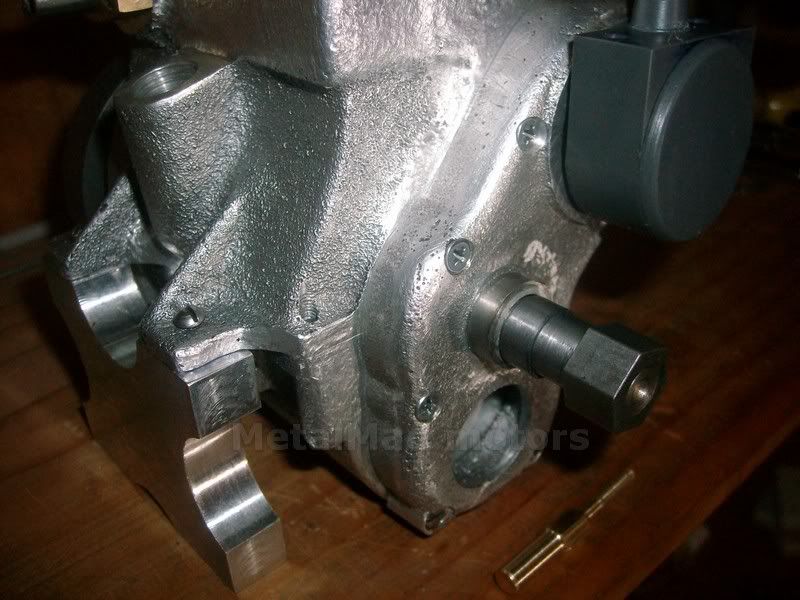
Thanks Dave Its coming along OK now but nothing more on the oil pump so far ;D
Have you started your Wallaby build log yet?
I'm really looking forward to it, You can count on it being my favorite th_wav
Hi Bez,
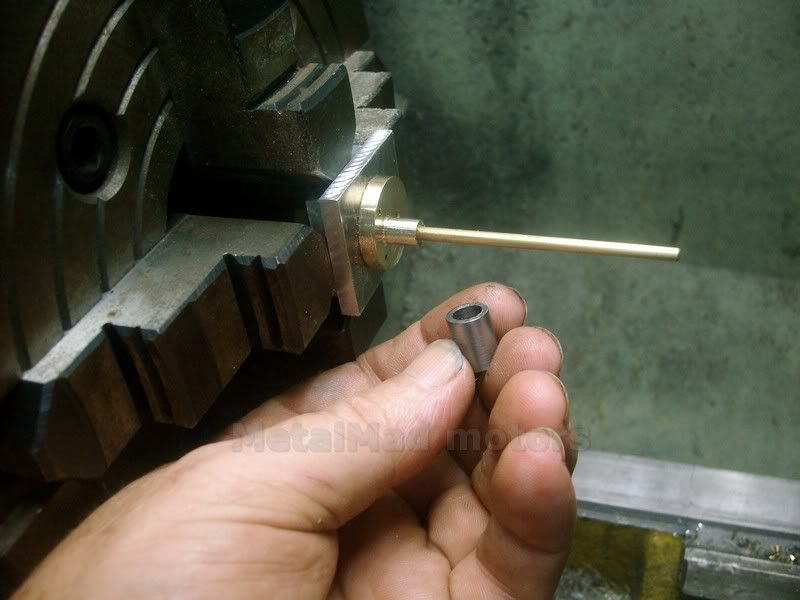
The Brass was just so pretty Rof}
Hi Bill
Thank you for that, I had forgotten that Stainless work hardens so nicely, I will try and get a Stainless welding rod tomorrow and try it out Thm:
Pete
 
I'm still methodizing the build process a bit....but hopefully I'll start posting this weekend....depends on the honey do list ;D

Dave
 
What Method, There's a Method ??? ??? :big:
Today I turned up the spring holder for the distributor and bolted up the timing cover, this was done by turning up a firm fit bush for the crank/timing cover and then using a sharpend pin, the same size as the thru hole of the cover to make punch marks to be drilled.
Between the bush on the crank and the distributor /rotor button, the cover is held exactly where it needs to be for marking.
Pete
tcscrew1.jpg
 
Went to see the quack today and turns out I'm a diabetic with a low Thyroid, guess that explanes a few things.
Anyway I decided to remake the inner cover of the oil pump and made a fixture using the PCD feature on the mill DRO.
I did have a bit of a Hiccup after doing the holes in the cover, I used a 1/8 two flute to drill the blind hole, After I was done I pushed the down button instead of the up :Doh: :redface2:
After indicating on the rod I left it in the cover during turning, That way you know its right if there is no wobble.
As expected the blind hole broke thru but I guess I can locktight a plug in or somethink, may not even need to do anything. Shown here with the oil punp gear boss.
Pete
oilpump.jpg
 
Pete

Sorry to hear of the slight "oops" you had there, but as long as it's fixable than no worries.

From my experience of long projects, when I start seeing the light at the end of the tunnel (project completion), that's when I subconsciously want to rush things and usually the inevitable happens. So I start consciously slowing down and double and triple checking things.

Looking forward to see it running.

Vince
 
Hi Pete,
In regard to your pushrods it doesn't look like there is any adjustment on the rockers or the rods. Instead of having to remake them every time they wear or you change head gaskets or mill the head why not do like I did on the 5 cylinder radial I'm building, make the pushrods form 2 pieces and thread them together with a locknut. You can use this same method no matter what material you decide to make them from.
gbritnell

IMG_4849.jpg
 
Hi Vince
No amount of checking fixes stupid :big:
I have to relieve the timing cover a bit tomorrow so the gear fits, then I'm hoping to drill the hole in the sump for the other side of the gear boss to run in.
once that's done I guess I can drill and tap the pump mounting holes.
It really is getting close now ;D

Hi George
The hex Bush on the rockers have an off center hole and its simply a matter of turning the adjuster and locking it up to set, and I have a Stainless steel welding rod that I will try out if I find the brass wears excessively.
I have adjusted the rods a couple of times and they seem to work well, so we will just see how it goes I guess. Fingers crossed :big:
Thanks Mate
Pete

rod.jpg
 
Hi guys,

Looking good Pete!

George, the pivots of the rockers are bored eccentrically to adjust for tappet clearance.....at least as designed.


Dave
 
Thanks Dave
stickpoke ;D
 
That's what happens when you type before coffee....
 
Today I turned up a short bush to stand in for the oil pump gear boss.
This bush allowed me to install the gear and inner cover exactly where it needed to be, in order to mark out and drill the sump hole to suit the longer gear boss.
Now that the assembly is installed I'm ready to drill and tap the outer holes, so far so good, everything turns over nicely and has gone together like clockwork.
Pete
op2.jpg
 

Latest posts

Back
Top