Walking Beam Conveyor

Home Model Engine Machinist Forum

Help Support Home Model Engine Machinist Forum:

This site may earn a commission from merchant affiliate links, including eBay, Amazon, and others.

Brian Rupnow

Design Engineer
Project of the Month Winner
Joined
May 23, 2008
Messages
14,993
Reaction score
8,287
Location
Barrie, Ontario, Canada
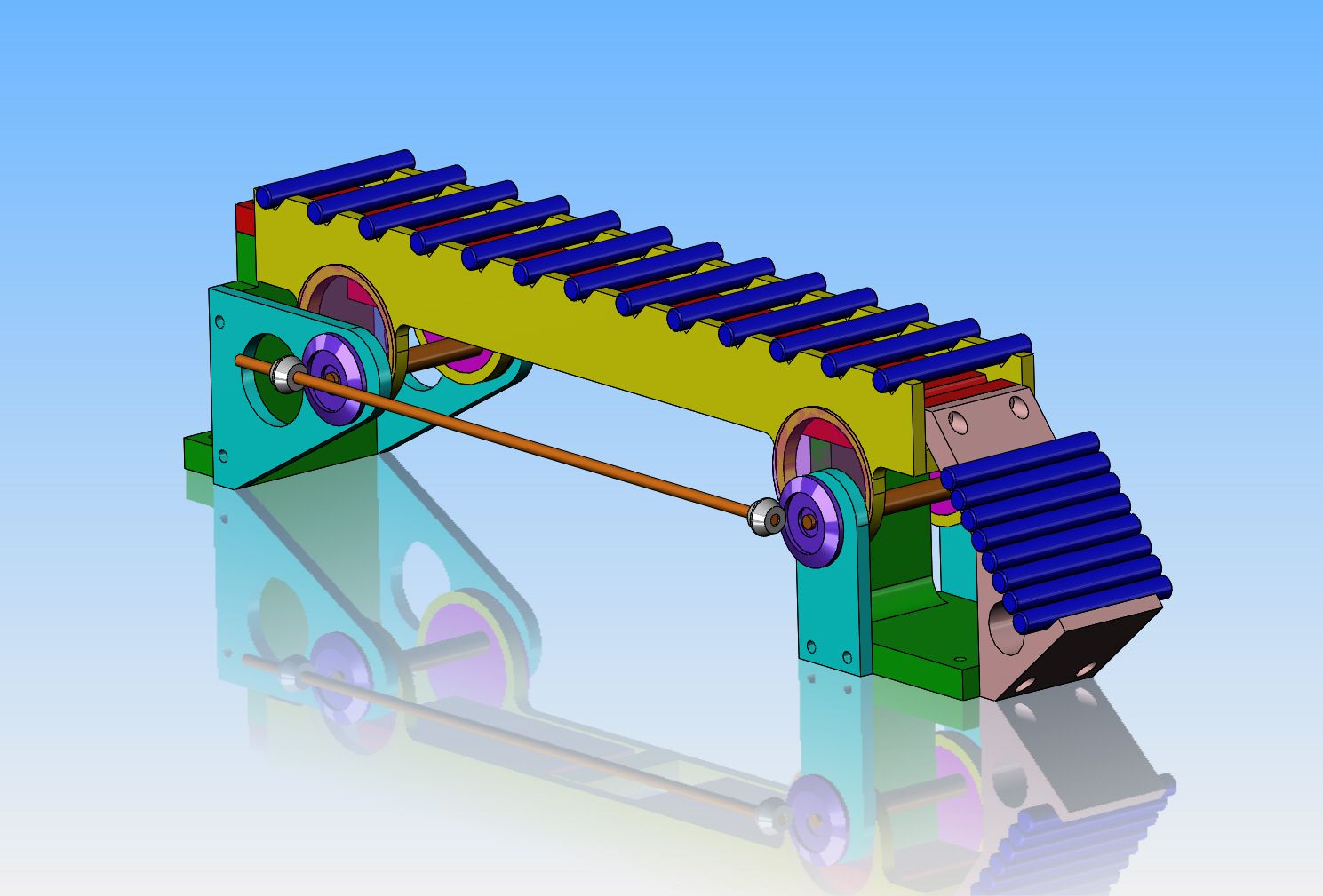
I am tired of building engines. I need another machine to drive with my engines, and this time I think I will try something "industrial" in nature. One of the more fascinating types of conveyors is a "walking beam" conveyor. These conveyors were, when first invented, used to convey a piece of material from one position to the next, to the next, thru a series of "stations", where the piece being conveyed had some type of automated function performed on it at each station. Newer "walking beam" conveyors are mostly driven by either hydraulics, rack and pinion gears, or a combination of both. Earlier walking beams were purely mechanical in their operation. I have been playing about with concepts this morning, and even went across town to the model R.C. hobby shop and purchased a couple of sets of metal miter gears to be used to transfer power from the blue disc seen at one end of the animation to the blue disc on the other end, utilizing a shaft drive like the older BSA motorcycles. This link takes you to a short video of the basic concept. I will be working on a fully developed 3D model of this machine over the next few weeks, and then hope to build it in my machine shop.----Brian

[ame]https://www.youtube.com/watch?v=ak2eMgt7yLw&feature=youtu.be[/ame]
 
Saw this one a while back and it intrigued me but I like your ball ladder better.

[ame="https://www.youtube.com/watch?v=759kPVhJKvk"]https://www.youtube.com/watch?v=759kPVhJKvk[/ame]
 
Another idea for this sort of mechanism. This linkage provides a near rectilinear motion

Transport Mechanism.jpg
 
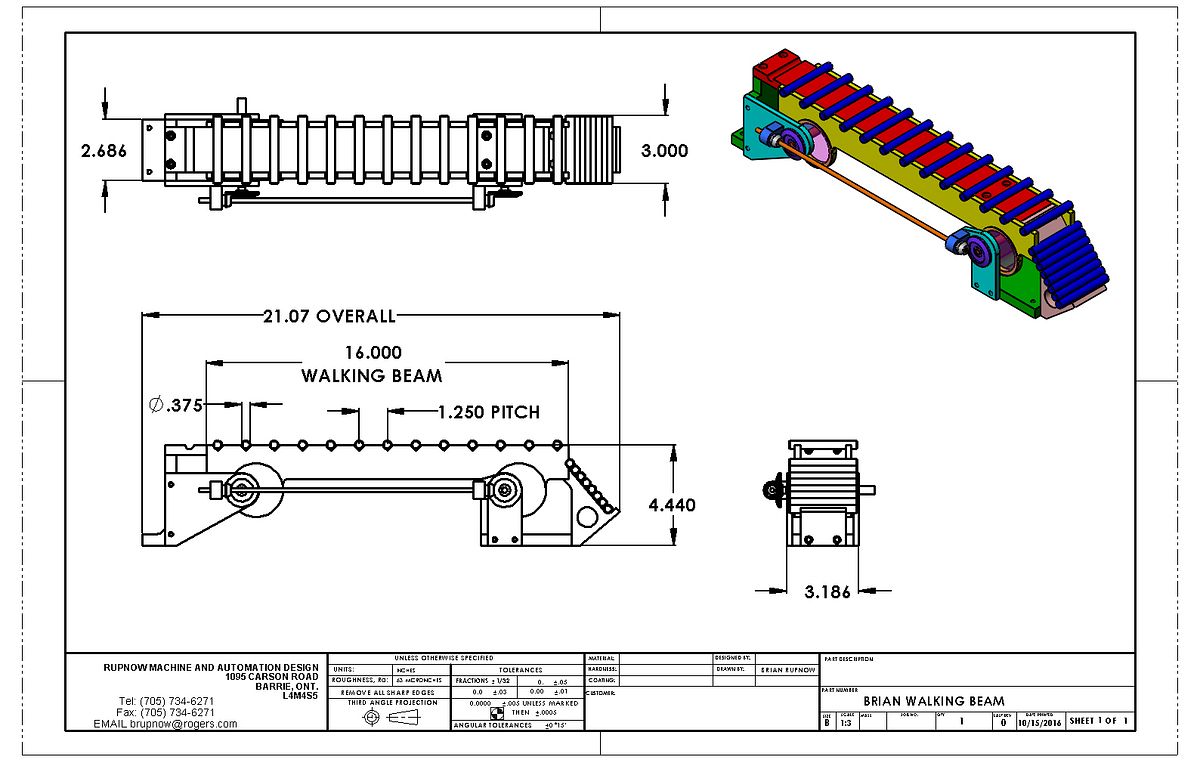
After looking at about a thousand different walking beam designs on the internet, I found one which is very interesting, driven by a rolling cam at each end. The trick part is that both cams have to rotate together at the same speed of rotation. This could have been accomplished with a really small chain drive between the shafts, but I chose to use a couple of pairs of miter gears, simply because they were readily accessible at the local R.C. shop. I have shown the accumulating ramp at the discharge end, but I haven't shown the magazine feeder at the load end yet. as an indicator of size, the dark blue pieces being conveyed are 3/8" diameter x 3" long.
 
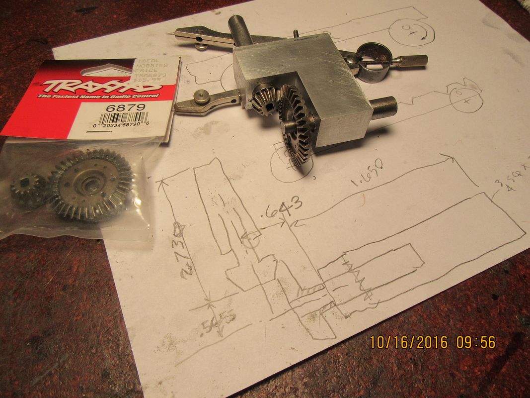
Any time I buy a set of miter gears, and they come pre packaged with no engineering information, the formulae for calculating the centers and offsets of the shafts is a trick. It is partly math, partly experience, and partly luck. And then of course, when you have figured it out, you still aren't certain until you make up a test block with the holes for the shafts which the gears are mounted on to see whether you had it right or not. I must have got it right this time, because they mesh very nicely with no binding. And another bit of gear trivia---Miter gears are always used on shafts which are at 90 degrees to each other. If the shafts are at some other angle, then the gears are known as "bevel gears" and have an angular number attached to the part number.
 
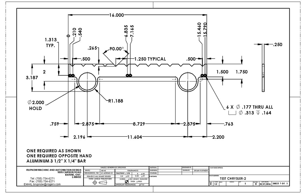
Having a rather crazy morning here. I haven't had any "real" work since June. Now two customers have called and both want me "right now"!!! I will try and work for both of them, just stagger my hours so they both get coverage. I phoned my metal supplier and ordered everything I would need to build the walking beam. That came to $80.00--far more than I anticipated. If I go in there and buy one piece of metal at a time, they don't charge any shop labour. If I order two or three things at once, then they charge me the shops labour rate for pulling and cutting the stock. It probably works out to be fairly inexpensive over a years time, but to swallow $80 all in one lump seems like a lot. I have decided to make this part first. There will be a right hand and a left hand version. Don't bother to copy or save this drawing, as there will probably be changes as the job progresses. I am making these pieces first, because it is much easier to make a cam on the lathe to fit the 2.000" diameter holes than it is to machine the cams first and then try to bore to an accurate enough size for a good rolling fit.
 
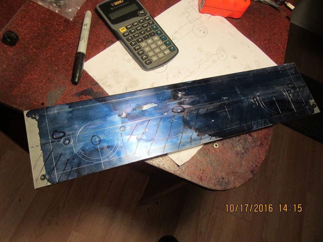
I picked up my material, and decided that I would start work on this project today. This first piece is actually two pieces, the right and left hand side walking beams. Since the two pieces have to be identical, I cut a 36" length in half, which gives me an inch to be trimmed off both ends, as the finished walking beam is 16" long. I drilled and tapped one plate and drilled close fitting clearance holes in the other, for #8-32 shcs. This lets me bolt the two plates together, and all of the machining will be done (except counterboring for bolt heads) while the two plates are together. This should give me a better chance at having two identical finished plates than if I machined them separately. You can see that I have laid out the profile and all the holes in the plate. I will use the digital readouts on my mill when I go to drill the holes----the layout dye is cheap, and it lets me know if I'm drilling in the right place. I trust the readouts, but it is kind of like wearing a belt and suspenders too.
 
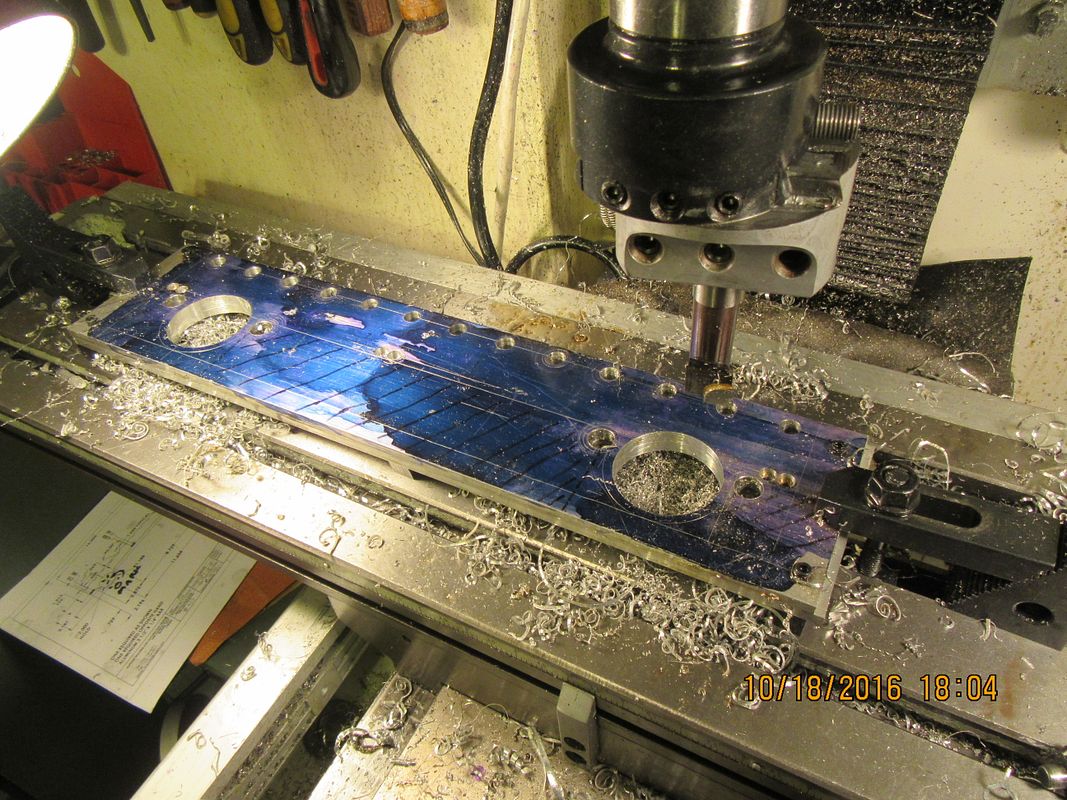
And that my friends, is a lot of holes!! I finally have a bit of "real" engineering work, so progress will slow a bit. I have bored the holes to about .005" undersize. The finish I get on bored holes is not spectacular, so by the time I get the inside of the two 2" holes smoothed out a bit, I will be very close to the finished diameter. Now I see a lot of 'sawing and milling' in my immediate future.
 
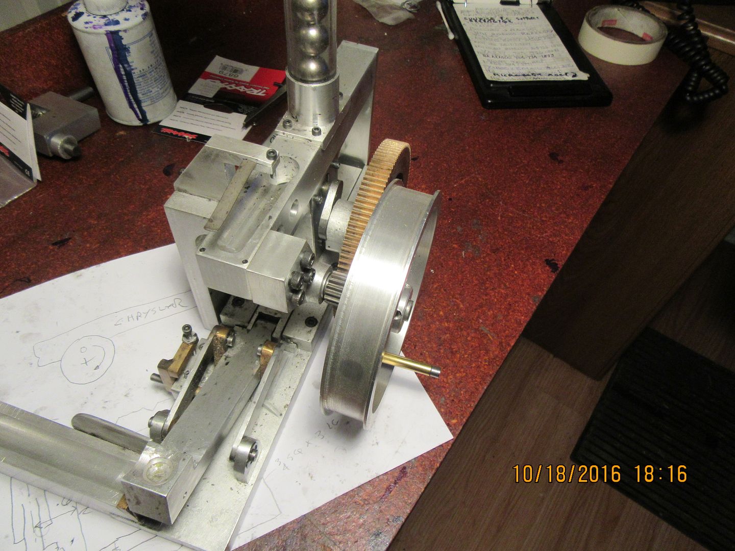
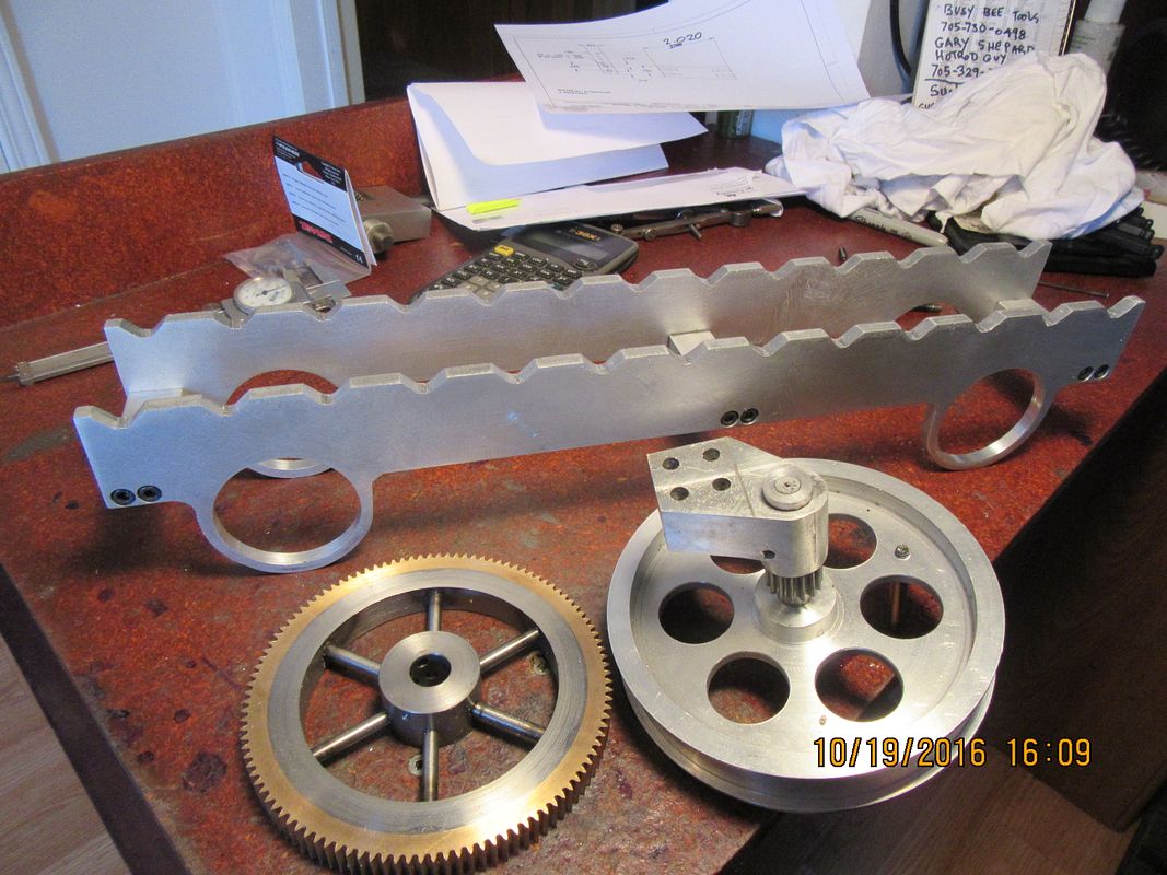
I may go a bit "steampunk" on the drive for this walking beam. I have a beautiful pulley and a set of gears that I made a few years ago for the marble automation machine that never really got finished. Walking beams, by their very nature should run at a slow pace, and they will benefit from the gear reduction torque multiplier as well.

 
This was a big job. Thank the Lord for bandsaws and belt sanders. I think this is going to become very interesting---
 
Looking great Brian. I like the idea of the reduction gear.
 
Herbie--I am always amazed that after more than half a century of mechanical design, that I can still get so damned excited about new projects like this. I have been in love with mechanical things all my life, and it's wonderful to see these things come to life right before my eyes!!!
 
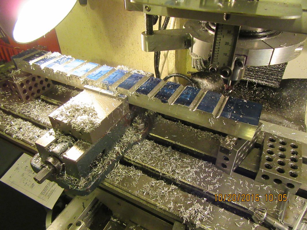
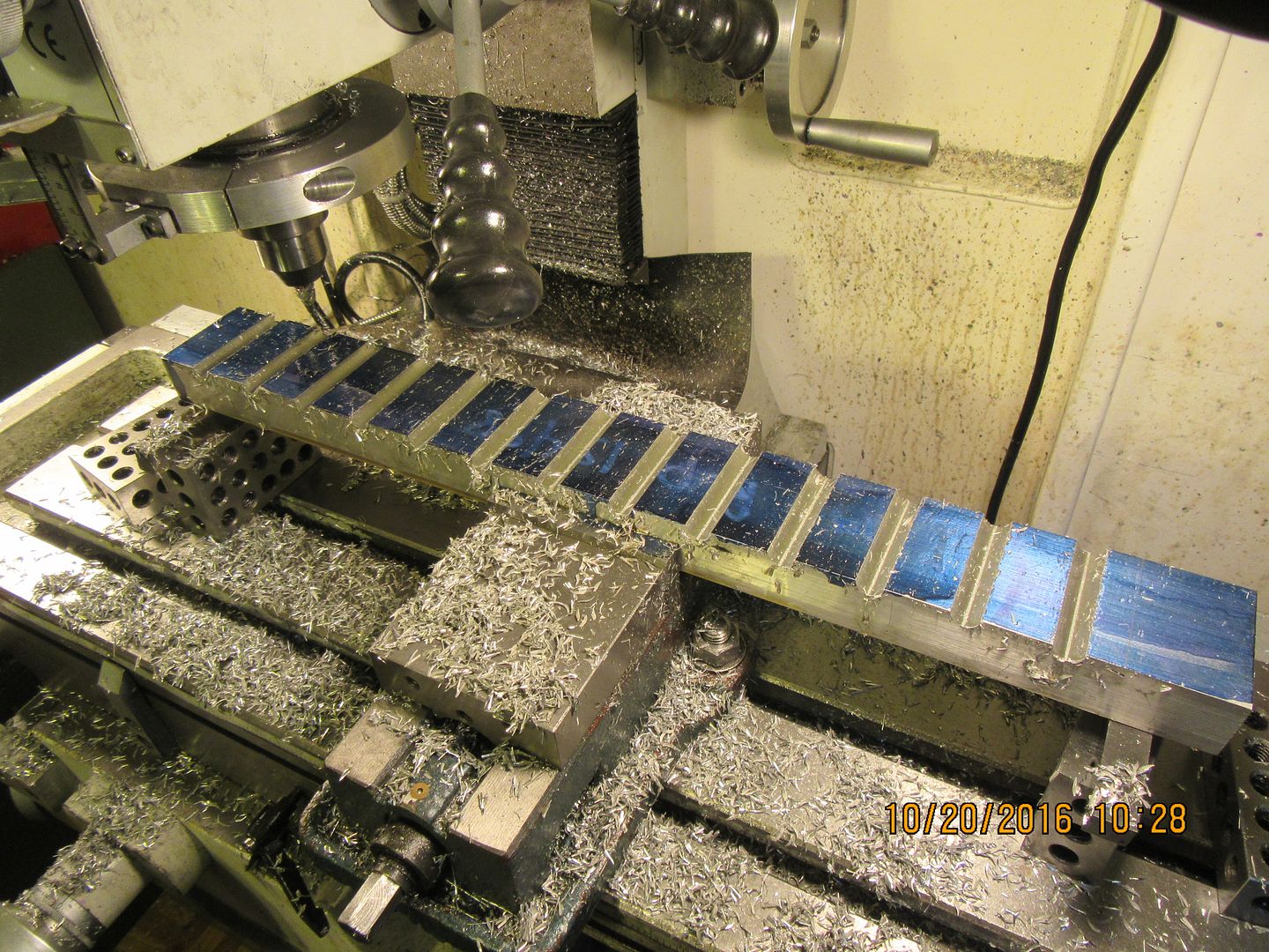
This morning I put all of the half round slots in the stationary part of the walking beam. I first gashed all the cuts 0.188" deep with a 45 degree chamfering tool. Each slot took 3 passes, one at .062" deep, then one at 0.122" deep, and a final at full 0.188" deep. Then I put in my 3/8" ball nosed cutter and took full depth 0.188" cuts in two passes , one pass for roughing and the second just to bring the table back and give a bit of a finishing "burnish" to the newly cut half round. I did it this way because ball nosed cutters really don't like to move a lot of material during a cut.

 
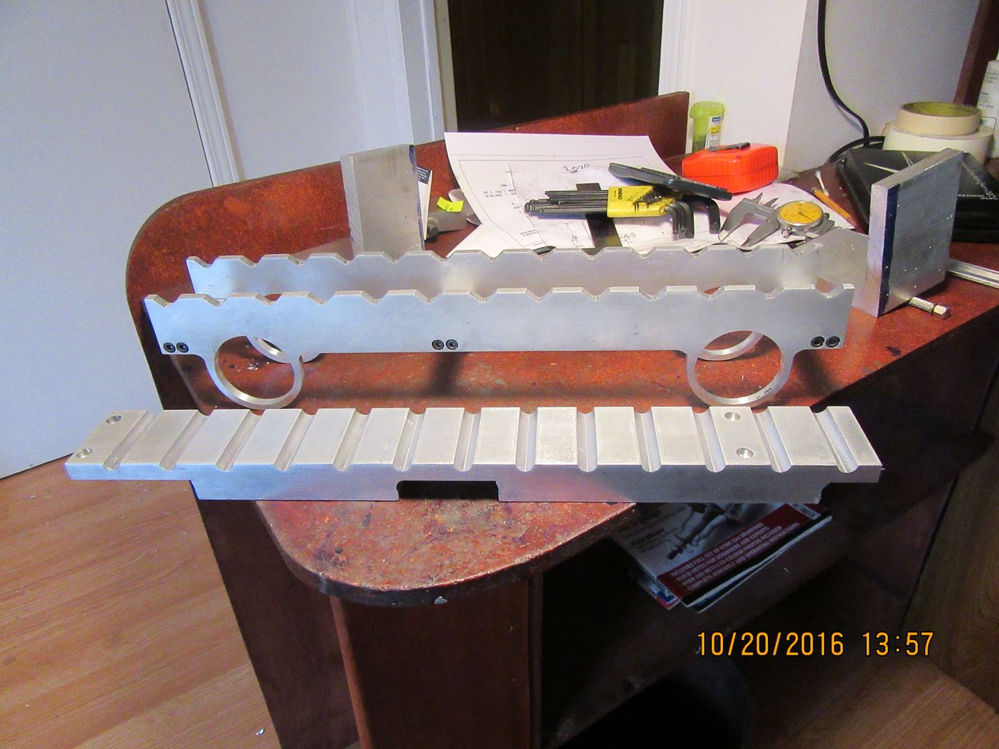
That went well!! I think that the pieces in the picture are the pieces with the most work in them. From here on in, I think most of the stuff is fairly simple.
 
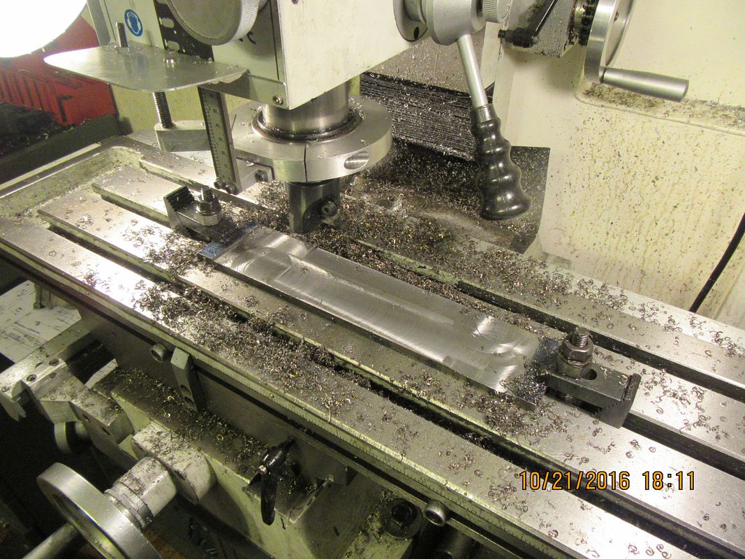
I couldn't buy 5/16" cold rolled flatbar, so I bought a piece of 3/8" instead. This is destined to become four 2 3/16" diameter "cams" that fit into the big holes in the side of the walking beam. I have a 2" diameter carbide face mill that I have used very few times, so tonight was the time to try it on the steel flatbar. This was a new experience for me. Someone suggested that I take a full 1/16" deep cut, but I just couldn't bring myself to do that. My mill is a fairly big tabletop model, but it's not a Bridgeport. I took three .016" depth cuts and one .014" deep cut, all at 500 rpm with lots of 'squirt on" cutting oil. The mill handled it alright, but it groaned a bit when I took the cut at the "shoulder" at each end of the bar. I expect that the flatbar will "banana" a bit when I take the toe clamps off, but that doesn't really matter for what I'm going to do with it.
 
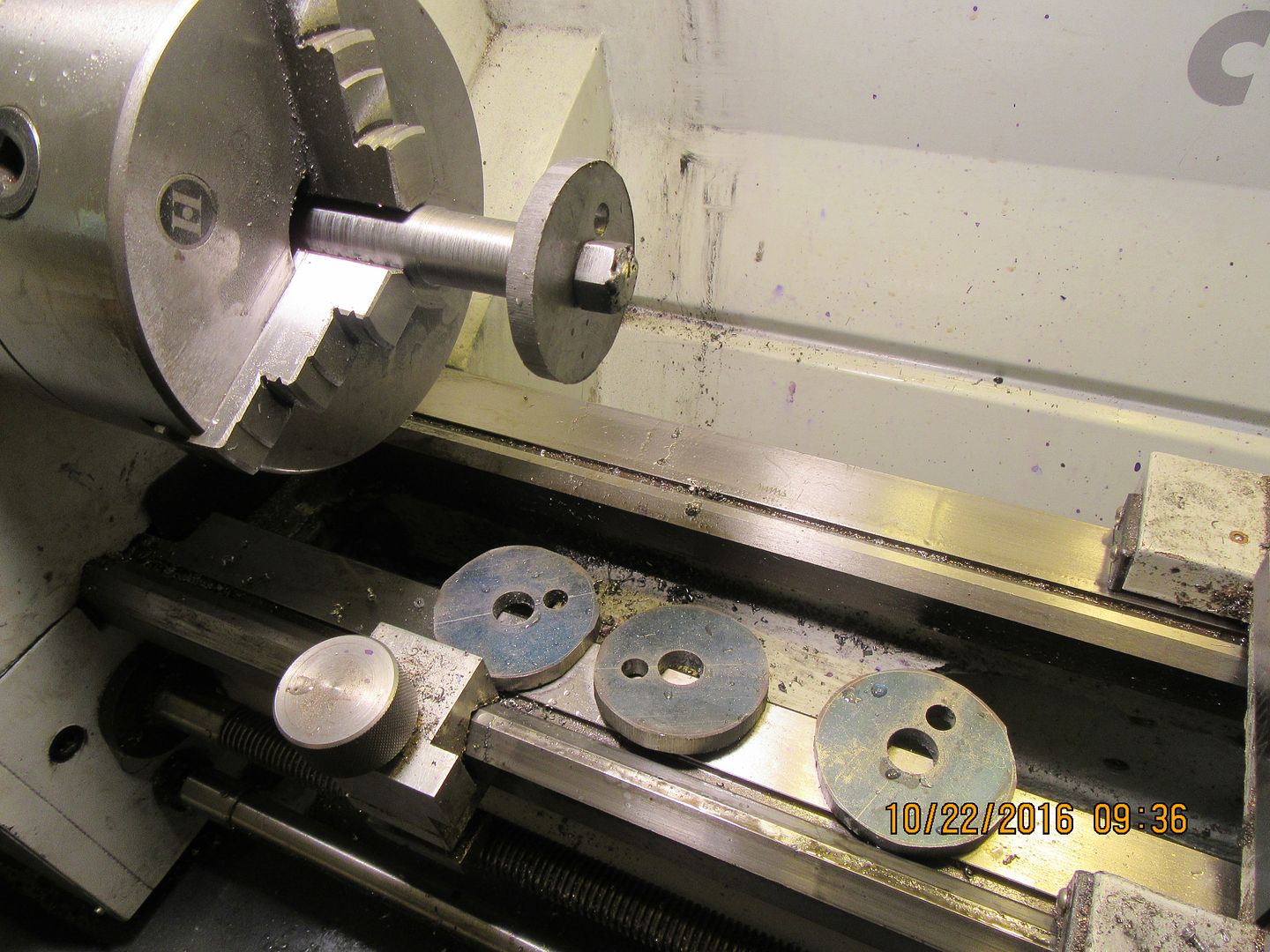
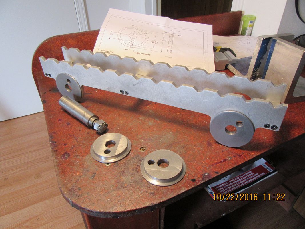
Here you see the bar which was machined to 5/16" thick, drilled and bandsawed into 4 separate pieces. I don't need that 5/8" hole in the center for any purpose on the walking beam, but I needed to drill and ream it so I could mount each plate on a shouldered arbor, to finish turn the outer diameter and to turn the "step" which allows the cam to fit nicely into the hole in the side of the walking beam. The 1/16" flange keeps the cams and the walking beam assembly in place after everything is put together. The 3/8" reamed holes which are offset from the center actually are for the axle. That offset is what gives the walking beam its orbital travel. In the second picture, two of the cams are in place in the side of the walking beam, and two are laying on the table with the shouldered arbor.


Latest posts

Back
Top