triple expansion engine

Home Model Engine Machinist Forum

Help Support Home Model Engine Machinist Forum:

This site may earn a commission from merchant affiliate links, including eBay, Amazon, and others.

peatoluser

Well-Known Member
Joined
Apr 19, 2010
Messages
174
Reaction score
2
although my long term goal is to build a loco, like a lot of model engineers, i'd also like something to put on the shelf as it were.
And after flicking through some of the free download books (thanks to Pat J's postings) i decided to build a marine steam engine.
After looking at Brunel's and Stuart's sites, the price of the kits are way out of my league, but i purchased the plans for Brunel's triple (to O.B. Boltons design published in M.E. in the 50's) anyway with the intension of seeing if i could scratch build it ,but put them to one side.
Months later, i ran into an ex work colleague (long retired, the lucky so and so) and we got talking etc. and to cut a long story short, a couple of days later he called round with a set of Newnes Marine Engineering books from the 50's.
this wetted the appetite again, so plans dusted of , and time to see if i could buid it from stock materials. But, as i'm not using castings, i thought i'd try and base it on some of the illustrations from Newnes.
Building the model would also be a good excuse to build some tooling and jigs i would probably need for the loco. So i think this is going to be a long build.

first up was to make the base. Decided to make this in 3 sections , fabricated box construction. (i'd post a photo of the page but don't know if it would infringe copyright), but with the main bearing housings made from 3/8.

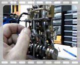
milling slots for main bearing bolts

eng033.jpg


and these are the parts for the high pressure part of the base
zzzzzzzzzzzzzz051.jpg

with the end part cut to shape using manually operated multi tooth cutters. with the intermediate and low pressure to do, like i said it's going to be a long post.
 
Hi, looking forward to your progress, as for long posts.... uhm... id be the last to critise ;D Im sure its going to be worth waiting for... ... enjoy!
 
Bit more hacksawing and filing today. Finished the 3 base platforms. Here's a photo of them together with part of the main bearing housings and some of the platework for the box sections resting in place. When i've finished filing the rest of housings and started soldering the box sections i'll post some more pictures.
bases2.jpg
 
Peter,

This is going to be quite a project! A heck of a lot of work goes into the triple expansion engines, I'm sure it'll be a great family heirloom. I'll definitely be watching, thanks for sharing.

Nick
 
I have an ambition to build a triple one day, so I'll be following this with interest.

Best of luck with your build Peter

Cheers
Steve
 
Well, finally finished filing the main bearing housings
xxxxxxxxxxxxxxxxxxxx055.jpg

now i have to make sure that the depths of the slots are all the same, so clamp them together and using a scrap piece of 5/8 bar, engineers blue and some riffler files (now I know what they're for!) make sure that i'm getting decent contact on all 6 and that they are level, although i dare say i'll have to repeat this operation after i've completed the bases.
xxxxxxxxxxxxxxxxxxxx061.jpg

xxxxxxxxxxxxxxxxxxxx062.jpg

Pat, you make a good point about pushing the envolope when scratch building. I think when i come to solder this lot up i'll soon find where about on the scale from "over-optimisticaly ignorant" to "knowingly competent" my skills lie. At least doing the job should keep me warm. In this weather (in England)after about an hour in an unheated garage my -er- 1/2 whitworths soon become a pair of 1/4 BSF's :big:
 
seem to have messed up posting photos. hopefuly here they are.
t3.jpg

t-1.jpg

t2.jpg
 
Thanks for taking the time to post your project. This looks like it'll be a great one to follow along with.
Dennis
 
Hi peatoluser

I'm really looking forward to follow your project, I have had the joy of building a Triple Expansion Engine my self :


Thanks for posting the video Mogens, if (when!) the going gets tough I know where to look for inspiration. Thm:
 
Well, I've cut all the plates for the box sections, so it's time to solder them up. I'm always nervous about clamping so many parts together only for something to move or joint gaps to disappear. Therefor in one respect I 'bottled it' a little, and welded then filed square some of the plates so as there would be less to go wrong when I light the torch. Veed the joints and used 1.6mm rods at 40 amps.
newnes065.jpg

Even with the plates welded and less to go wrong, I still tend to overheat the job, and i don't want to calculate how much solder I fed in, but I did eventually get everything stuck together.
newens076.jpg

the small webs (1/4 by 1/4 16g) are a pain to hacksaw and file, so I need to make a slitting saw arbor and a jig to cut them on. (there's 32 on each block). I've also realised that the best way to procede with the other two bases is to use a length of 5/8 square bar to align all the bearing housings up before I bolt them to there respective bases. If I make each base individually, when I come to bolt everything together, there's no guarantee that the bearing slots would be in-line. So some bar ordered along with more supplies of solder. I think I'll be doing well if I can get all 3 the bases finished by Christmas.
 
Pat,
I think line boring is the best way , but with a tiag lathe it's not an option. I intend to make a faceplate fixture and bore them individualy. So long as i mark which way they go into it, and assemble them the same way, I shouldn't have too much misalignment. Although i do fully expect to have to use shim to get them aligned given the construction method of the base. hopefully sketch gives the idea. Got the method from 'Simple Workshop Devices' by Tubal Cain.
nawnes013.jpg
 
I like the way you're going about this peatoluser. Seem to be achieving a lot with the minimum of equipment. So I guess your model is quite a bit smaller than O.B. Bolton's one? The Bolton triple expansion is pretty big right?

Cheers
Steve
 
Not really Steve. The dimensions of O.B.Bolton's are cylinders 7/8 , 1 1/4 , 1 3/4 by 1/14 stroke. All slide valves. Connecting rod 2 11/16. Stands 8 3/8. I'm sticking with the cylinder and stroke sizes. may increase the con rod size.Toying with the idea of having one set of columns for forward and reverse instead of the crosshead being guided between two columns , but that may be beyond my machining capabilities. most of the changes i will be making are largely cosmetic as i'm not using castings but fabricating.
yours
peter
 
Pat,
thanks for the link to Sotherns. managed to down load 8th edition (1916) where some of the foldouts have been scanned.
yours
peter
 
Sounds like a good size Peter. I really like this project :bow:
 
Bar arrived, so drill some holes to bolt everything together.
boltingbasesinline.jpg

turn over and drill tapping size, clearance and countersink all at one setting before moving onto next hole. Generally I don't like to use c/sk screws to bolt parts together. No waggle room if things go wrong.
cskboltssecureblocks.jpg

then it's just a question of assembling each base and soldering up. If its possible I tend to tack weld parts together.
All brazed up. Just the webs to fit, but i'll use soft solder to fit them. The 1/4 plate at the end will be used as a drilling jig for the enfd plates.
BRAZEDUP-1.jpg

I now need to machine the bases for the columns so they are all at the same hight, and file/scrape the ends of each base to make sure that when they are bolted together they don't pull the main bearing slots out of alignment. Probably have to fettle the slots again to make sure that they are still at the same hight.
peter
 
At last some machining. Although I still have the webs to solder, as i'll be using soft solder, there should be no distortion.
Clamp each base to the vertical slide and skim the pad of the column. Lock the saddle in this position and then as each base is milled they will all be the same hight.
millingcolumnbase.jpg

I also relieved the centre part of the vertical faces of the bases. This was to make it easier to fit them together.
millingrelief.jpg

Two bases are slid towards each other located on the bar and feelers are used to check for gaps. It's a case of filing so both sides are touching. This is easier to do with the centre portion slightly recessed.
checkinggap.jpg

You know it's right when you can clamp both parts together without jamming the bar.
clamped.jpg
 
This is fast becoming an impressive piece of fabrication Peter. Nice work

Cheers
Steve
 
Found it quite fiddly trying to hacksaw and file 1/4 by 1/4 webs , so used the situation as an excuse to make that slitting saw arbor i'd been promising my self for some time. Simple jig on the cross slide and soon had them done.
cuttingwebs.jpg

I found soft soldering these almost as difficult as silver soldering the bases. I ended up tinning the base and then sweating the webs on.
Managed to get them bead blasted and although they looked O.K. , on closer inspection I could see where some of the solder had not run down on some of the webs, and that some of them needed re-aligning. When you drown the job in the amount of flux like me, it's difficult to see if everything is O.K. but i'll fix these hiccups later. at this moment don't want to spoil the finish.
next job was to use the drilling jig to drill the end flanges of the bases. If the jig is marked sides A and B, you clamp A to one face and then B to it's corresponding face, then every thing should line up.
guide.jpg

Then it's a case of bolting everything together.
BOLTEDBASE.jpg

once i've checked the alignment of the slots, it's a question of making all the chock blocks and then hopefully I can start on the main bearings.
 

Latest posts

Back
Top