Toolpost Needle Valve Grinder

Home Model Engine Machinist Forum

Help Support Home Model Engine Machinist Forum:

This site may earn a commission from merchant affiliate links, including eBay, Amazon, and others.

Brian Rupnow

Design Engineer
Project of the Month Winner
Joined
May 23, 2008
Messages
14,991
Reaction score
8,285
Location
Barrie, Ontario, Canada
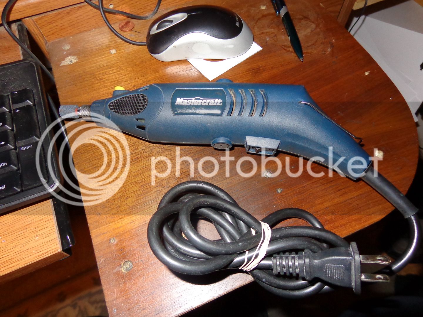
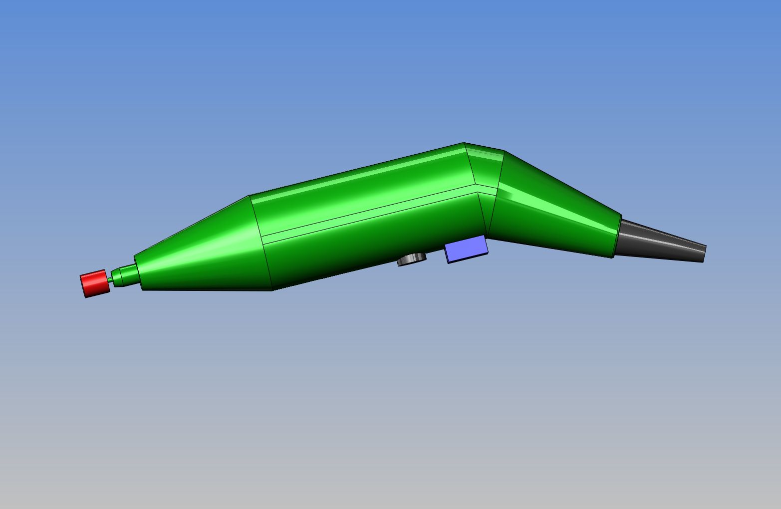
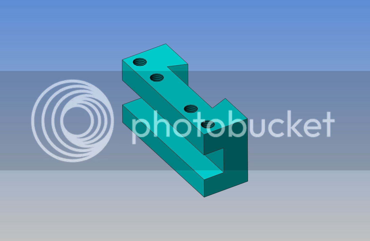
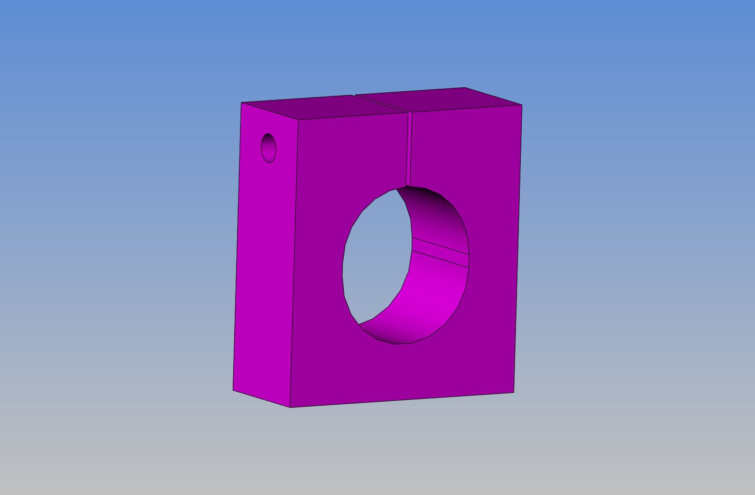
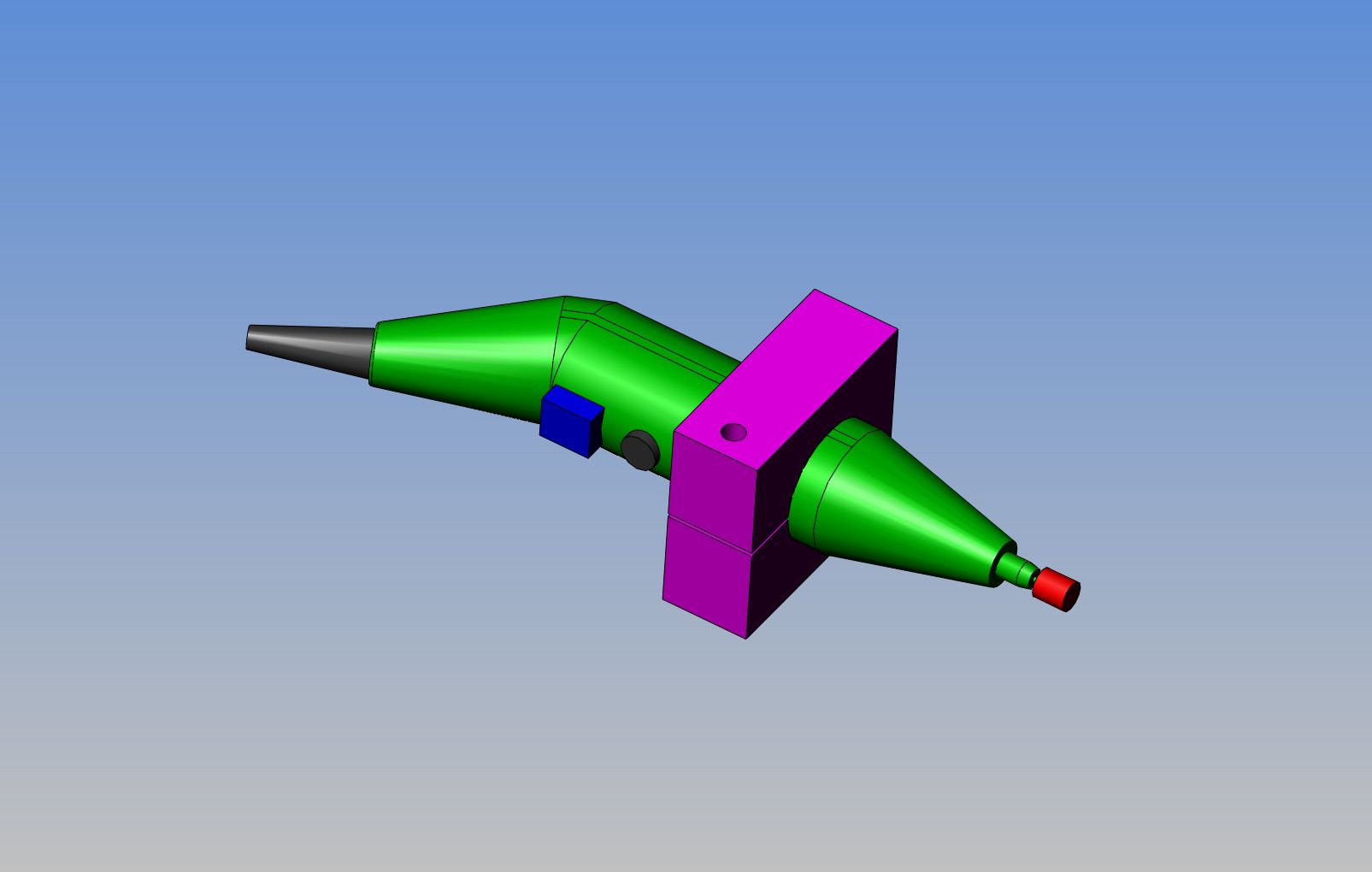
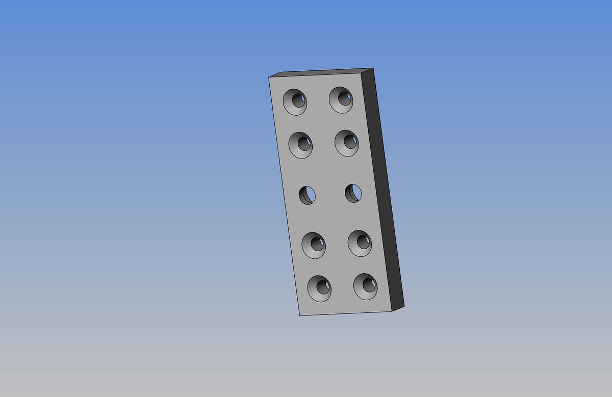
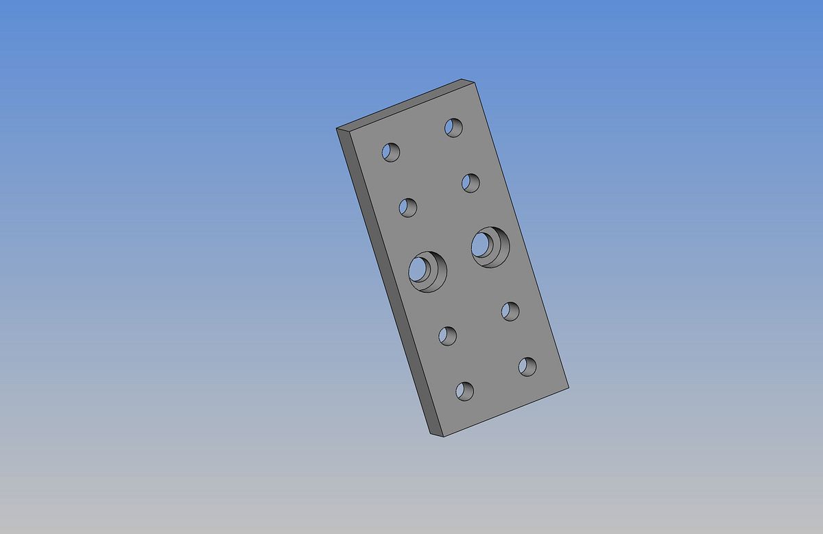
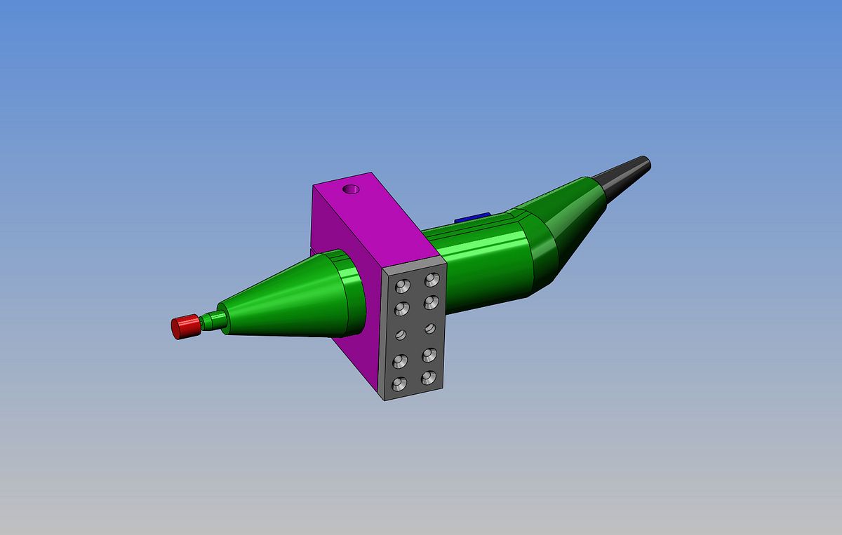
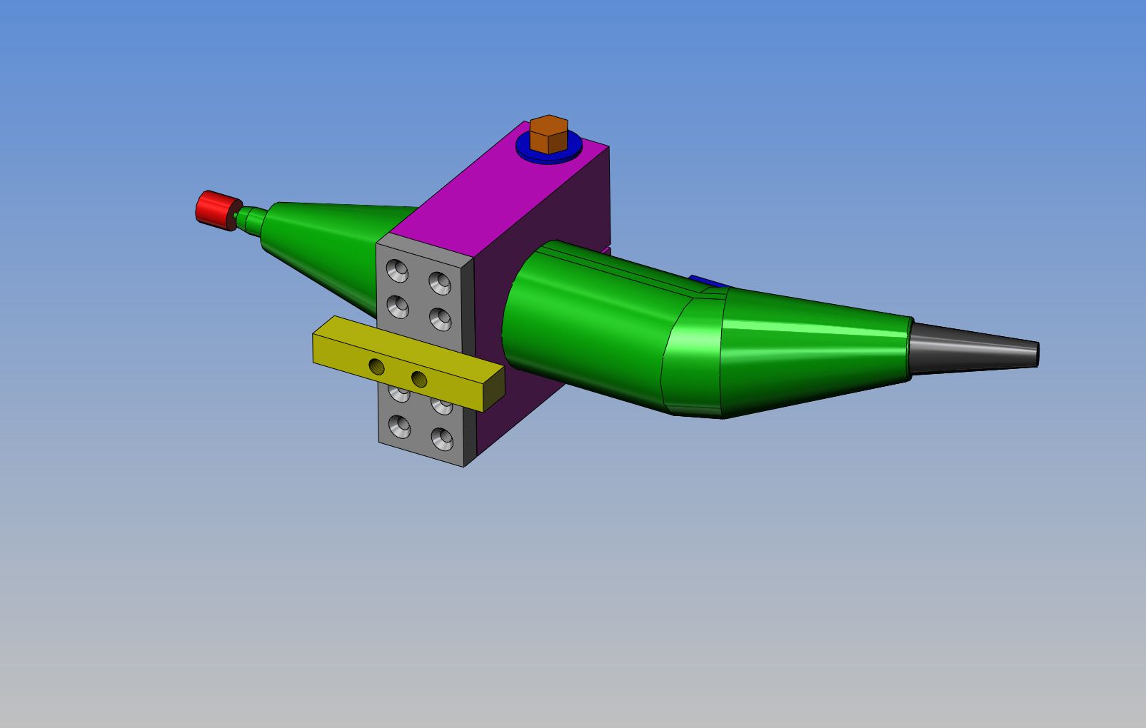
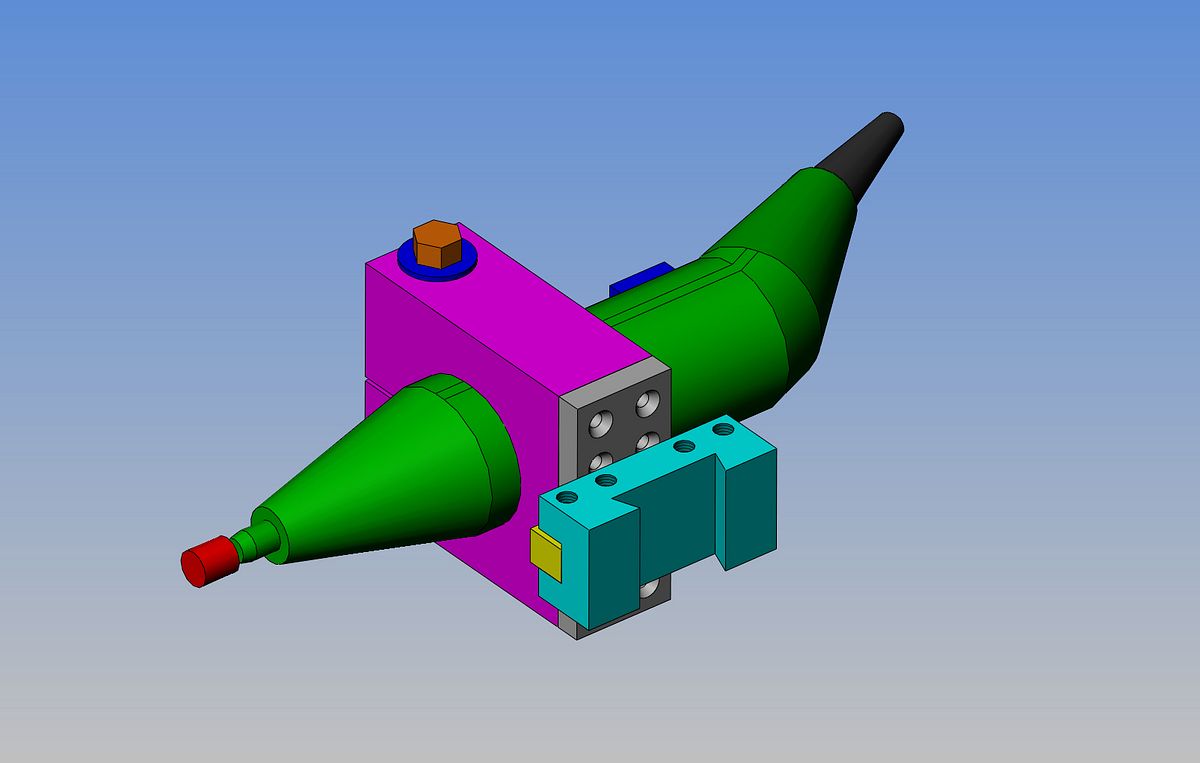
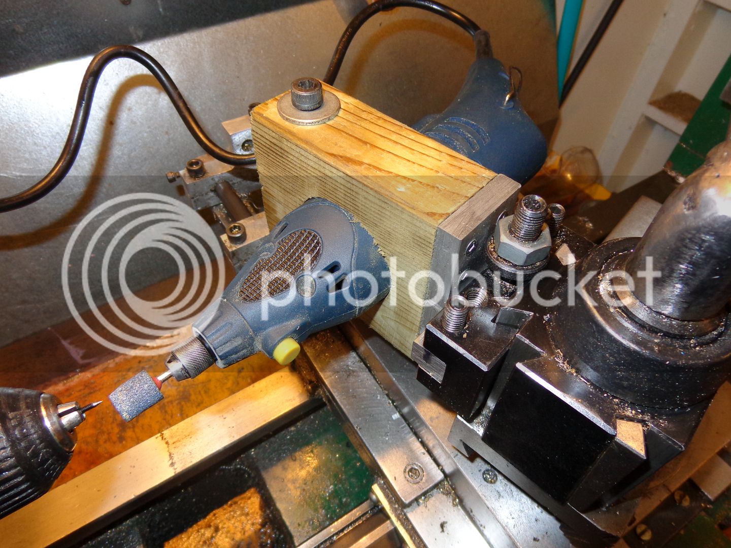
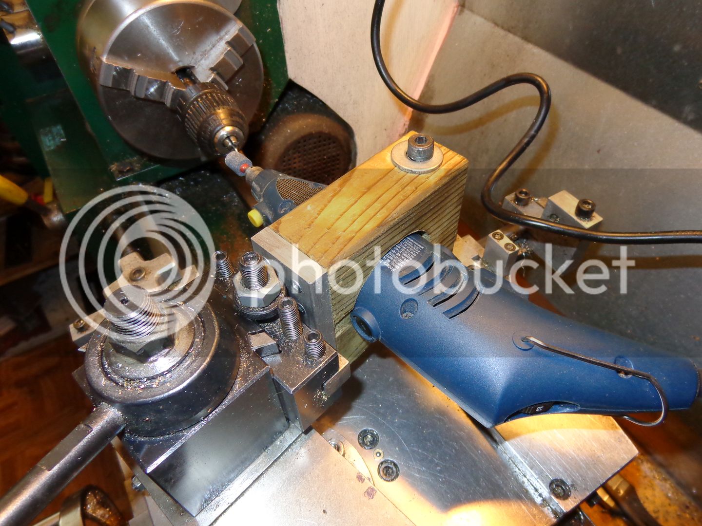
I have to create a tool to grind needle valves. I simply can not turn something as small as I need on my 10" lathe. All of these small engines I build call for a #2-56 threaded needle valve with a 30 degree included angle taper, and I have no way to make one. Necessity is the mother of invention, and although I wouldn't be so bold as to say I invented this, some of you may be interested enough to follow along. The tool in the picture is a Dremel "clone" sold by Canadian Tire in Canada. Its not a bad little grinder, but its only good for freehand work. I am going to build a mount to hold it securely in my quickchange toolpost. Its too light to do any serious work with, but I bet it will be just fine for grinding very small valve faces and needle points onto #2-56 bolts. The mounting bracket I design and build is going to be quick, and its going to be free. More tomorrow.
BADRINGS002_zpsbd6b9ce8.jpg
 
I use my cordless drill to spin the needle stem against my 1" vertical belt sander. I also use this method to round off the corners of sharp pins & screws that I have cutoff.
 
Last edited:
I made a similar thing to what you are making. Check the nose of that thing to see if the bit behind the chuck unscrews. The dremel has a thread under there and it is quite a simple process after that. You will find many uses for it once you do it. I wil be watching along.

Brock
 
I'll start this out with a quick 3D model of the grinder I have. It is dimensionally correct, and as I have to do a small amount of layout work I will need this.
DIEGRINDERTOOL_zps564c8fdd.jpg
 
The next thing we do is take a peice of wood 1 1/2" thick---pine, spruce, or hardwood, doesn't really matter. We have to cut a hole in the center that exactly natches the profile of the die grinder. That will be the toughest part of this whole build. I got lucky---My die grinder is two half circles 1.95" in diameter seperated by a straight section 0.175" long, (as measured by my calipers) so it is an easy profile to recreate. If your tool has a more complex profile in the area to be clamped, you may have to use a glue gun and small bits of cardboard to copy te exact profile. (I can explain more about how to do that if you need it.) The block of wood will have a sawcut through one side, and be drilled through for a 3/8" clamp bolt. You can't see it, but I have put a counterbore in the far side of my wooden block so I can epoxy a 3/8" steel nut into it.
WOODENHOLDINGBLOCK_zpsf3f49297.jpg

ASSYOFTOOLANDWOODBLOCK_zpsf6d5940c.jpg
 
Cool project Brian, do you think there may be a benefit in it to do I.D. (internal) grinding?

John
 
Next up will be to make an aluminum part, which in my case turns out to be 1 1/2" x 3.45" x 3/8" thick. It is drilled and countersunk 8 places for woodscrews to go into the wooden block. From the other side, it has two counterborres holes thru on center for 1/4" shcs. It is screwed with #10 wood screws to the side of the wooden block opposite the sawcut. Keep the woodscrews just short enough that they don't breal thru into the cut out for the grinder. For a really strong connection, run the screws in, back them out and coat them with 2 part epoxy, then run them back in.
ATTACHMENTPLATE1-FRONT_zps1c9e4264.jpg

ATTACHMENTPLATE1-REAR_zps0b5a0a35.jpg

ASSYOFTOOLANDWOODBLOCK-2_zpsc2f80337.jpg
 
The last piece to build will be made from mild steel. In my case it is 1/2" thick x 5/8" deep x 3" long. It has two 1/4"-20 unc holes tapped in it to line up with the c'bored holes in the piece screwed to the wood. I forgot to tell you---Its a trick!!! Bolt the steel and aluminum parts together BEFORE you screw the aluminum piece to the wood.
ASSYOFTOOLANDWOODBLOCK-3_zps75d87a71.jpg
 
Now, if you have lead a pure life like I have, and all your stars are aligned, it will fit into your tool holder like this, it will be height adjustable to be exactly on the horizontal center of your chuck (I checked on mine) and it will be adjustable to any angle. More after lunch!!!
finalassy--grinder_zps9f0319a1.jpg
 
Thanks for posting that, Brian.
- It's nice that you're posting your work so that everyone can benefit from it.

What CAD system are you using ?

Joe
 
Cool project Brian, do you think there may be a benefit in it to do I.D. (internal) grinding?

John
No John---I repeat myself---This is not for any medium or heavy grinding jobs. It ONLY has any value for accurately grinding SMALL things. The motor simply doesn't have enough power to do much beyond carburetor needles and very small (as in 3/8" diameter) valve faces.----Brian
 
Don't get the notion that I'm totally altruistic. I have to make these drawings so I can make the parts myself. Have fun. I'll post a pic and a review of how it worked (or didn't work) after I make it.---Brian
ASSYOFTOOLANDWOODBLOCK-DRAWING_zps74a76482.jpg


WOODENHOLDINGBLOCK-DRAWING_zps8bbd6b89.jpg

ATTACHMENTPLATE-2-DRAWING_zps6d873dcd.jpg

ATTACHMENTPLATE1-DRAWING_zpsfde875c9.jpg
 
I am editing my post to say that this great experiment didn't work worth poop!!! It seemed like a great idea, and my first results were promising, but there is simply too much flex and wobble in the set up to really do any worthwhile work. Sorry about the formerly positive comments. I was mistaken. Oh well, Nothing ventured, Nothing gained..---Brian
NEEDLEVALVEGRINDERRUNNING001_zps26e9d5e6.jpg

NEEDLEVALVEGRINDERRUNNING002_zps933babde.jpg

NEEDLEVALVEGRINDERRUNNING003_zps3f0c396d.jpg
 
Last edited:
Charles--Yours looks sturdier than mine. Mine is all made of plastic, even the screw on nose cone and threads. Now that I've had a chance to use mine a bit more, I'm not nearly as impressed with the results. I wouldn't really recomend anyone build this. It doesn't cost anything but your time, but sadly the results aren't as good as I had first thought.---Brian
 
Brian, did you see this post?
http://modelenginenews.org/techniques/needles.html

I noticed you used a cylindrical grinder. Is it making continous contact on the taper & maybe why its bending back teh stock from pressure? Maybe it would be better to use a disk style grinder, lighter grit & finer feed. A disk would run along the taper & only cutting a smaller portion at a time so less bending force? Kind of like sharp lathe bit contact vs big flat cutting surface principle?

FWIW, my experience with grinding stones typically packaged in offshore moto-tool kits must be made from bits of sidewalk cement. They cut crappy, heat the material & seem to clog easy. I bought some good quality rotary stones from a jewely supply place & they were like night & day difference (on hardened pin shafts). Dont recall what they were but they come in an assortment of colors like grinding wheels. They didnt cost that much & offered dozens of styles to choose from.

Is there any way to support the end of the wire in a makeshift tailstock to stop flex? Even a block with a hole in it? Maybe you could grind the majority of taper in a mid section & then lop off the end so it stays supported as long as possible?
 

Latest posts

Back
Top