Three cylinder Radial

Home Model Engine Machinist Forum

Help Support Home Model Engine Machinist Forum:

This site may earn a commission from merchant affiliate links, including eBay, Amazon, and others.

Russel

Well-Known Member
Joined
Oct 19, 2009
Messages
108
Reaction score
0
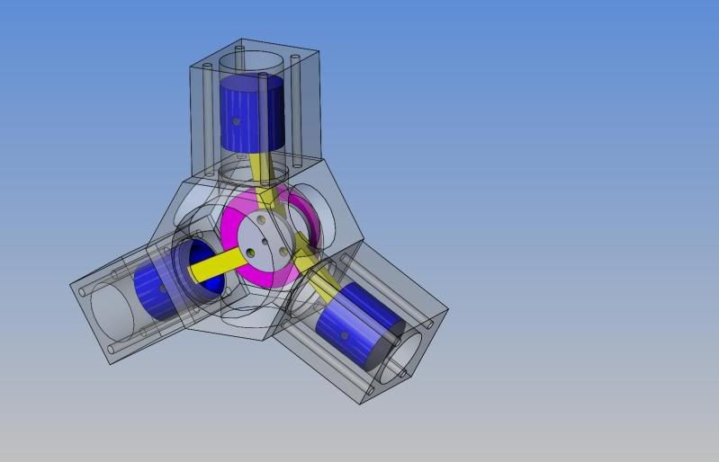
I have started my first complicated project. I have done a little wobbler, and a few simple odds and ends, I think it is time to dive into a more advanced. I decided to build a three cylinder radial engine. If you follow the this link and scroll down to engine 11, that is the one.

http://www.john-tom.com/html/ElmersEngines.html

I decided to start with the crankcase. I figure that it is going to be the most difficult part for me to make. Hopefully, things will get easier from there.

The day before yesterday, I believe, I cut the basic stock and faced the two ends for the crankcase:
Crankcaseblank.jpg


Yesterday, I bored out the inside of the case and drilled and reamed the quarter inch hole in the back.
CrankcaseBored.jpg


Today, I had a little mishap with the DRO wires on my Sherline 2000 mill, so I didn't get the turning fixture completed. But, I did get the milling done on it so I can start with the lathe tomorrow.

If you are interested in my little mishap with the DRO wires follow this link:
http://www.homemodelenginemachinist.com/index.php?topic=6619.0

Anyway, here is what I got done today:
Turningfixture.jpg

I'll post more as thing progress.

Russ
 
You're headed in the right direction, Russ. Getting started is sometimes the biggest step.

Dean
 
Metal Butcher did an amazing job on his radial build. I hope I can make one that looks as good!

It's nice to get an idea what the parts really look like. The plans have photocopied photographs in black and white that aren't very clear. Metal Butcher's radial engine posts are a good motivating factor for me!

Russ
 
I didn't get much time to play today, but I did get a little done on the turning fixture. I tried and tried, but I couldn't get the turning fixture straight flat against the four jaw chuck. I could center it, but couldn't get the back square toward the headchuck. So, changing gears in my head, I decided to use a faceplate. Man, what a difference! I marked, drilled and tapped holes in the faceplate to hold the part. Then put the faceplate on the lathe and gave it a couple light passes with the cutting bit to true it and screwed down the part. Worked like a charm. I just spent more time than I thought it would take to rig it up. Anyway here are the photos:

Here with the not so perfect four jaw chuck:
Turningfixture-1.jpg


and here a close up of the faceplate with the turning fixture mounted on it:
Turningfixtureclose.jpg
 
Russel said:
Worked like a charm. I just spent more time than I thought it would take to rig it up.

This is the life of the machinist, Russ. Setting up is often the bigger part of the job. Many times it an hour and a half dialing in and squaring the job for a 10 minute cut.
I'm surprised you had trouble with the Sherline four jaw. I had one at one time. Was a well built piece of kit.
You usually can't go wrong with the face plate though. Face it off and you know it's square!

Keep up the good work!

Dean

 
Looks like a neat project. I did some serious studying on Elmers 3 cyl. radial to figure out how all those connecting rods met on a common hub before I designed my 5 cylinder radial engine.---Brian
 
Deanofid said:
...I'm surprised you had trouble with the Sherline four jaw. I had one at one time. Was a well built piece of kit....

The chuck works great for long parts, or parts that you can mount right against the face. But the one I have seems to have about .0015" difference in the height of the jaw steps. To be honest, I thought the chuck was the easy answer and that the face plate was an old outdated part of the lathe. Through my own recent experience I have learned that the face plate is a very useful part of a lathe system. (I see custom faceplate plans forming in my head.) Just like turning between centers with a dogleg. I thought that was outdated by the chuck until I needed to lathe stuff with as much precision as my little Sherline lathe could muster. I learned respect for turning between centers that day. Experience is a good teacher.
 
Oh you bet! Turning between centers is the way to go at it if you want straight shafting. Great for when you need to do work on both ends of a piece too. You can flip a piece over and over and know it will be on centers every time.

Sherline has a follow steady that they sell for their lathes that will come in very handy for you if you are going to turn long pieces of round stock. Lots of neat stuff in their catalog to try to find a use for..
:)

Dean.
 
Today I got the flats of the crankcase machined. I don't know if I did it the best way, but the method I used seemed to work well enough. Instead of using a locating pin and machining the flats with a lathe I used a CNC rotary table. Lots of set up here! mount the RT to the vertical support and align mount the vertical support to the table and align Y axis and Z axis. Use a DTI on the round part of the rectangular turning fixture and center it on the RT. Then I made X axis passes in three stages with a final pass slightly cutting into the turning fixture to catch the little bits that the X axis passed didn't get. I'm tired, but happy!

Here is my humble little milling setup:
RotoryCNCBench.jpg


Here is a little closer so you can see the CNC RT:
RotaryCNC.jpg


And finally, a close up of the crankcase still mounted to the turning fixture:
CrankcaseFlatsClose.jpg
 
Nice work, Russel. Lots of work, but a job well done!

Chuck
 
Russel said:
I'm tired, but happy!

MB wrote:

Tired= A good day in the shop.

Tired, but happy= A really good day in the shop!

Note; The set up you used is the best way I can think of. Elmer machined the flats on his crank case with a milling head mounted on his lathe. Something most of us don"t have.

-MB
 
For what its worth---This is the model I built of the engine you are working on when I was figuring out how the con-rods all ended on a common "plane" when I was designing my radial.----Its not complete---just layed in enough stuff to study the part I was interested in.----Brian
ASSY-ELMERRADIAL.jpg
 
Thank you for the encouragement everyone!

Brian, that's a cool 3D model of the engine.

Well, I managed to get a little done today and learned a little in the process. I think I have the Sherline boring tool worked out.

Boringtoolside.jpg


One problem I had was keeping the lower part of the boring tool in contact with the cutting adjustment screw. I solved that by using a newspaper rubber band to hold the lower part again the adjustment screw. Worked like a charm. My left hand on the Allen (hex) wrench to unlock and lock the lower part of the tool and my right hand to turn and hold the adjustment while locking the setting. The other problem I encountered is that the adjustment screw would unscrew many turns while the tool was in use boring the hole. So, I used another rubber band to hold the adjustment screw and keep it from unscrewing while the boring tool is cutting. One other problem that I encountered before was an inconsistent adjustment from the screw. I solved this problem a while back by drilling and tapping a block of brass and using that as a jig to make the end of the screw flat. Originally it was concaved with an inconsistent surface.

Screwboringtool.jpg


Screwendboringtool.jpg


Not that I have figured out these little enhancements, I am very happy with the consistent results that I get boring a hole with the boring tool. Up to today, getting a hole the size that I wanted seemed elusive enough that I prefered not to use the boring tool unless I absolutely had to. Now I feel confident I can machine a hole to within a thousandth of and inch. I spot drilled the cylinder bore in the crankcase then drilled it with a small drill bit, just about as big as the flute width of a half inch drill. Then, carefully, at about 200 RPM, I drilled the case with a sharp half inch drill. Afther that the boring tool finished the job to the required size.

In order to tap the threads for the cylinder mounting screws, I made a 1.15" diameter tapping handle for the tap and used the drillchuck as a guide for the back of the tap. I also made a small cutting oil applicator, much like a watch oiler only bigger, to apply cutting oil to the tap while tapping without flooding everything with oil.

Tools.jpg


Here is the crankcase with one of three sides bored, drilled and tapped....two more to go.

Crankcasewithfirstbore.jpg


You can see a couple of minor screw ups that I did in this last photo. I used a center drill that was too big to spot drill the bottom right cylinder mount screw. Not a real problem, there are plenty of threads deeper in the hole. If I have to, I can repair it. And the lower left edge between the side I bored and it's adjacent side you cans see where I didn't back out the endmill enough as I advanced the RT to the next facet while machining the flats the other day. As I invest more time in this part I find myself triple checking everything...I don't want to start over now! Anyway, two more side to drill tap and bore, then three holes to drill in the end and I'll be ready to start the next part.

Russ
 
You're getting along nicely, Russ, especially since you had tool troubles.

I had a little airplane once that ran on a rubber band. I didn't know they made boring heads like that too!

Dean
 
Great pics Russ. Believe it or not...I think they're very helpful to us newbies.
 
Deanofid said:
You're getting along nicely, Russ, especially since you had tool troubles.

I had a little airplane once that ran on a rubber band. I didn't know they made boring heads like that too!

Dean

Thanks, we learn from our mistakes!

It's kind of funny because it's not the tools problem that I don't have three arms. But, the rubber bands did the trick...good for little air plains, and Sherline boring tools. (Oh yeah, good for the morning paper too.)

zeeprogrammer said:
Great pics Russ. Believe it or not...I think they're very helpful to us newbies.

Hey, I'm one of those newbies! I've learned quite a bit from the posts, especially with photos, so I figured I would do my part and post things with this little engine as they develop. That way maybe the next guy won't make the same mistakes as me. Besides, you guys are great motivators!

Russ

 
Got another side of the crankcase ready for a cylinder. Things when much quicker that the other day when I was playing with rubber bands and making a tapping handle for my 2-56 tap. I am really enjoying this now that I feel like I have a better handle on my little machine tools.

Anyway, here is a photo of the tapping handle, ready to tap a 2-56 hole. The tap is loose in the drill chuck so that the chuck acts like a guide.

Taphandle.jpg


After drilling and tapping the cylinder mounting holes and steam port, I drilled the case for the cylinder to a half inch so that I could use the boring tool. The 4 Jaw self centering chuck comes in handy in this operation.

BoreDrill.jpg


The setup almost looks comical. I find that if I pre-drill a hole just about the size of the flute thickness on the half inch drill bit, and use a good sharp 1/2" drill bit at about 150 to 200 rpm I get pretty good results without overworking my little machine.

Borepredrill.jpg


Borepostdrill.jpg


I was so pleased with the smooth progress today that I felt the need to clean the crankcase and take a more aesthetic photo:

Crankcase2bores.jpg


One more side to bore drill and tap...


Russ
 
Looking good, Russ.

I know that I always enjoy it when a part starts looking like a part instead of raw material :big:

Cheers, Joe
 

Latest posts

Back
Top