Three cylinder Radial

Home Model Engine Machinist Forum

Help Support Home Model Engine Machinist Forum:

This site may earn a commission from merchant affiliate links, including eBay, Amazon, and others.
Still moving right along, Russ. It's looking good.

The small hole you drilled in the crankcase, followed by the larger drill bit is the norm for many of us, especially those of us with small machines. (The little hole is called a pilot.) Often the pilot will help the larger bit make a straighter hole. There's some controversy about that, but I usually drill a pilot when I have a large hole to drill. Yeah, it does look kind of funny.

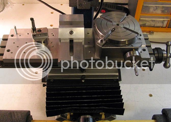
I have a suggestion, but please don't take it as criticism. In the interest of safety, you should ditch those rags you have covering the lead screw, or whatever you are using them for. One stray chip off that drill bit will grab that rag and suck it into the works so fast you won't know what happened. In doing so, it will fling chips all over your shop, and on you, and the rag whipping around can do quite a bit of damage when it catches on something, (like the work piece, or worse, a finger).
Just a thought.

You can use heavy construction paper to make gaiters to cover those lead screws, and it won't pose any safety issues.

Keep up your good work! Thanks for sharing the build with us.

Dean
 
Dean,

Suggestions and criticism are always welcome! You are correct, I really shouldn't have shop rags that close to the action. Even with the little machines that I am using I have seen some pretty long chips! I will take your advice and use construction paper, or maybe paper towels, to cover the lead screws until I get a chance to make some better accordion covers.

Thank you for the safety tip!

Russ
 
Russ, paper works pretty well, and is easy to work with. You can buy them too. I've seen them a few places on the web. Maybe at Little Machine Shop.

These are about six months old on my little Taig mill, similar in size to your Sherline. Can't see the back one, but is the same as the front.

waycover.jpg


Dean
 
Thank you Deanofid and Twmaster! I found this video on folding a bellows, but wasn't sure what to use for material. Now I know where to get the material.

[ame]http://www.youtube.com/watch?v=EV-eHIGzMPg[/ame]
 
Nice job with this engine! This is yet another engine I've been wanting to build but only modeled it and animated it in SolidWorks.

RADIAL ENGINE.JPG
 
Well, more of the same today. I finished one more "facet" of the crankcase. Nothing you haven't already seen. Everything went very well and I enjoyed myself confidently drilling tapping and boring.

Following Deanofid's advise, this time I didn't use a shop towel to cover the lead screw. I made some bellow covers out of regular 8.5" by 11" paper. The funny thing is that it is not only safer (check out those chips in the photo) it worked much better at keeping the leadscrew clean! Thank's Deanofid!

Russ

Guardleadscrew.jpg
 
Very clever! They are also very simple and inexpensive to replace!

I have chip deflectors on my lath, mill, and band saw made of corrugated cardboard!

Their not much to look at, but they work great!

-MB
 
It has taken me a few days to get back to this project. You know how those little side projects pop up sometimes.

Today I drilled and cut threads for the foot of the crankcase.
footscrewholes.jpg


Then drilled the steam ports that connect with the cylinder steam ports.

Cylsteamports.jpg


Then, and this took the most time, I mounted the rotary table to the mill table, mounted the crankcase jig that I used before and with the help of a DTI centered the jig to the rotary table. Then I mounted the crankcase to the jig with a single 10-32 screw in the middle and centered it to the rotary table with a DTI. When that was done I used the DTI to sweep one of the case facets with the DTI to align the side of the crankcase with the mill X axis. I set up 6 divisions on the CNC rotary table controller and proceeded to center drill, drill and tap the crankcase cover screw holes.

Drill.jpg


drill2.jpg


tap.jpg


So far, that's 18 2-56 holes drilled and tapped and 2 5-40 holes for the base. Only 6 more 2-56 holes to drill and tap and the spot for the vent.

Russ
 
That looks great Russ.
I sure hope you didn't jink things with that last statement about 'only 6 more 2-56 holes'. :big:
Did you make that 'handle?' for the tap?
 
Hi Russel tracked you're radial build down.

Great work

Stew
 
zeeprogrammer said:
That looks great Russ.
I sure hope you didn't jink things with that last statement about 'only 6 more 2-56 holes'. :big:
Did you make that 'handle?' for the tap?

Thank you for the praise. Tapping the holes isn't really difficult, just very time consuming. I made the tap handle disk earlier in the project with my lathe and bench drill press. At the time I had the crankcase carefully mounted on the mill and didn't want to disturb it. The other day, while I had the rotary table squared up on the mill, I was looking for anything else I could machine with it and gave the tap handle disk a little embellishment. I've use the thing almost enough (it seems) to polish it with my skin! The new grip works well and using the 1/4" drill chuck as a guide keeps everything straight, so I'm not concerned about jinksing myself. (Oops, there I go again!)

SBWHART said:
Hi Russel tracked you're radial build down.

Great work

Stew

Thank you Stew! I'm almost done with the first part.

 
Russ that really is going well, great photography too

Nick :bow:
 
Nice documentation, Russ, and the crankcase is looking good!
That's quite a few tapped holes for one piece. Hold your mouth right..

Dean
 
Thank you for the kind words gentlemen. :)

I've gotten a little side tracked with some small tool projects and such, so it has been a few days since I've worked on the little radial. I spent a couple hours working on the crank case today and finished the drilling and tapping with the exception of the vent. I am going to move on to some of the other parts after today and leave the finish (bling) and vent for later. I wanted to complete the most difficult tasks on the most complicated part and I think I have done that. So, here is the case with the valve side case holes drilled and tapped. I won't bother to explain the process because it is basically the same as when I did the other side of the case earlier.

Here it is still in the jig.
Casetappingdone.jpg


The threads look pretty good. It's not like I've had any practice or anything ;)
2-56threads.jpg


Here is the crankcase:
Casefront.jpg


Caseback.jpg


More to come...
 
Russel, watching with interest and waiting (impatiently) for more. Looks good mate keep it going... Artie ;)
 
It's looking very good, Russel. The tapped holes are just fine. Almost any tapped hole that doesn't have a tap broken off in it looks good!

Keep it up!

Dean
 
Deanofid said:
It's looking very good, Russel. The tapped holes are just fine. Almost any tapped hole that doesn't have a tap broken off in it looks good!

That's true!

It's just that it got to the point with this part that after tapping the first dozen 2-56 hole, I felt like I should bring a book to read while I was doing it. :p

I was planning to start on the crankcase covers today, but ended up doing some much needed cleaning and reorganizing in the shop. When that was done I was ready for a beer. I should be working on the covers tomorrow.

Russ
 
I got started on the crankcase cover today. First I hack sawed off about a half inch of 1.75” aluminum rod.

stock.jpg


Then, I put the most flat end against the chuck and faced one side.

Faced.jpg


Then center drilled and drilled for a 10-32 screw to go through it. I am going to make a bushing for the quarter inch shaft that will pass through this part. In the mean time I just need a center hole to hold it up against a jig so that I can machine it. So, I face the other side up to the fastener that is holding it to the jig.

Flippedandfaced.jpg


Then machine the part that fits into the crankcase. Then take it off the jig, mount it to the chuck and face the center where the fastener held it to the jig.

Finalfacingcomplete.jpg


I flip it over, mount it back to the jig and machine the other side.

Othersidecut.jpg


Then, after cleaning oiling and putting the lathe back on it's shelf, mount the cover to the RT on the mill using the original crankcase jig and zero it in.

CentercoverinRT.jpg


I centered the part with a edge finder, set the X axis offset and programmed the CNC RT controller for 6 divisions. Center drill, drill and bevel the edges on the holes and Ta Da! After spending days on the crank case, I can hardly believe that I almost finished a whole part today. It just need the bushing machined out of brass and the center of the cover bored for the bushing.

_DSC0228.jpg


_DSC0227.jpg


It's starting to look like something! More to come...

Russ


Looks real nice, Russ. Lovely.
Nice old Starret DTI, too. Or maybe it's new. They haven't changed much!

Dean
 

Latest posts

Back
Top