


Bill_Rittner
Active Member
- Joined
- Jun 11, 2015
- Messages
- 26
- Reaction score
- 11
The bench that my old South Bend came on was never solid enough no matter how much bracing I put on it. Recently I bought a used RF-30 and I needed a spot for it in the shop. When I got the mill a new bench for the lathe was well under way. I wanted the 2 machines next to each other so I decided to move the lathe to another room in my shop.
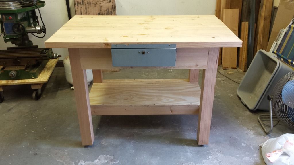
The new lathe bench is finished and waiting for the machine. It is built from Douglas Fir that I had on hand. I am fortunate in that I have a complete woodshop that allows me to build anything I can design. But you don't need a woodshop to build this bench. It can easily be built from lumber from the big box store.
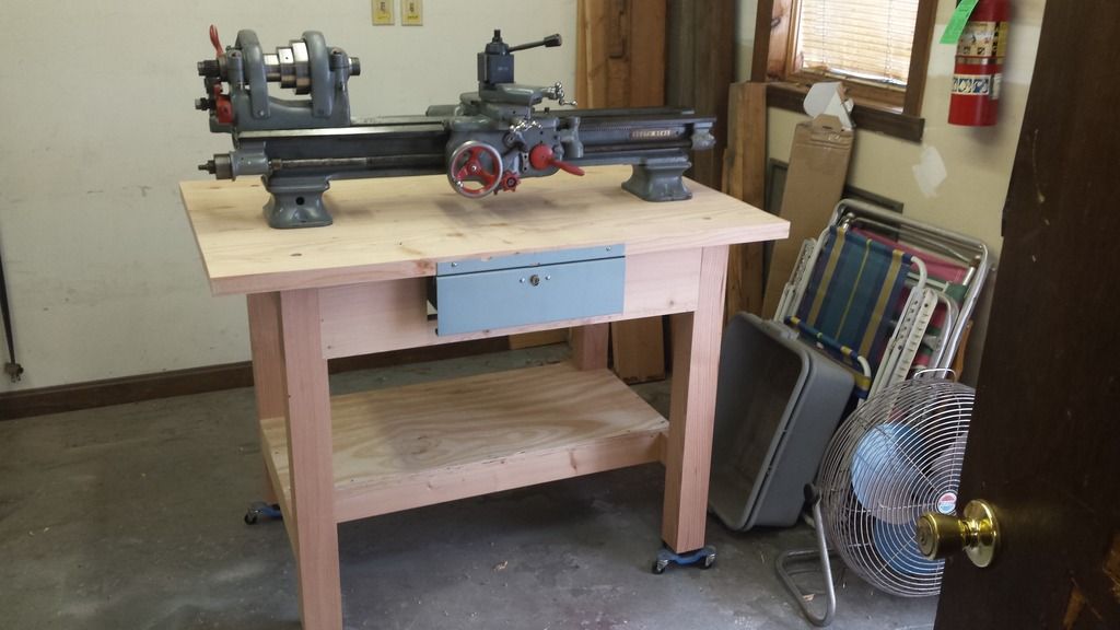
The lathe bed assembly setting on the new bench. In this shot you can see the dollies under the legs. This allows me to keep the machine out of the way until the final setup. Then they will be removed.
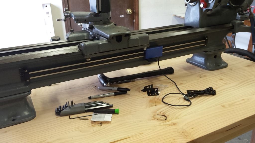
Here you see the scale for the inexpensive DRO installed. I had this system waiting for an opportunity to be installed on the longitudinal axis. It just required drilling and tapping 2 holes in the bed.
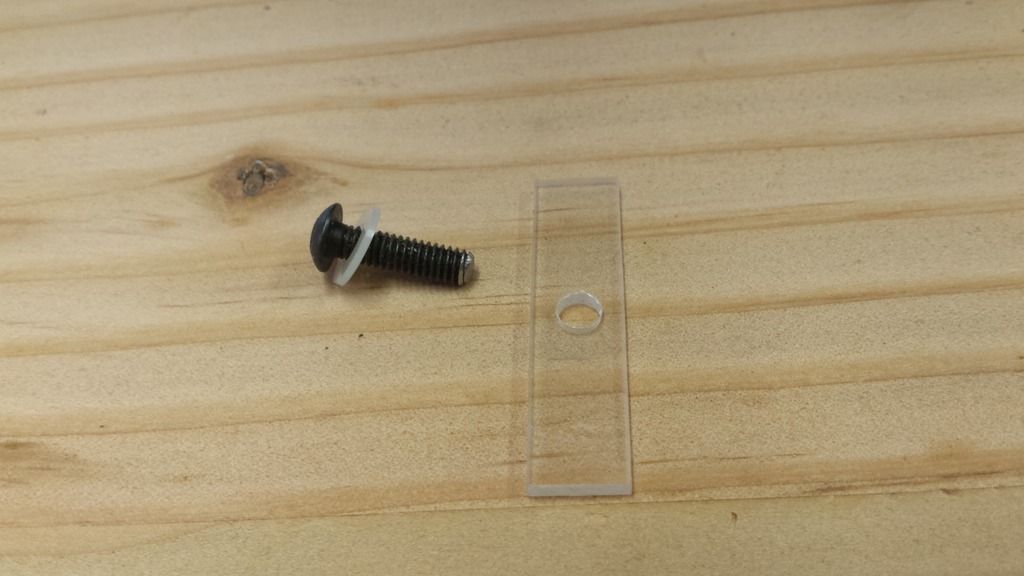
My research showed that the scale needed to be isolated from the machine to avoid electrical interference from affecting the readings. In order to achieve this I made a pad to fit between the scale mounts and the machine from acrylic and put a nylon washer on the mounting screws.
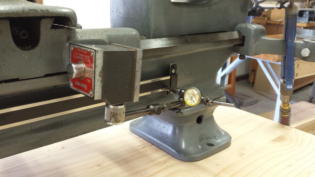
Next the scale had to be trammed parallel to the travel of the axis on the face. This scale is quite flexible, unlike glass scales, so getting this perfect is really not necessary. I shimmed it to within 0.010" and that should be fine.
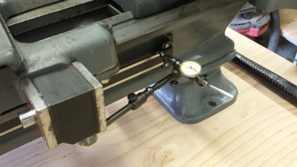
The next step is to tram the scale parallel to the axis in the vertical plane. The scale is not flexible in this plane so I trammed this to 0.001" This completes the installation and setup of the dro scale.
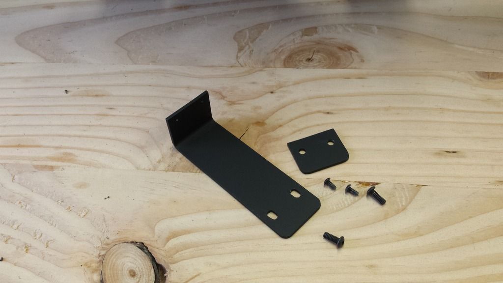
The next step is to fabricate brackets to connect the dro scale reader to the lathe carriage. This is the bracket, spacer, and screws. The bracket and spacer are aluminum painted black. To attach this to the lathe carriage I drilled and tapped 2 holes.
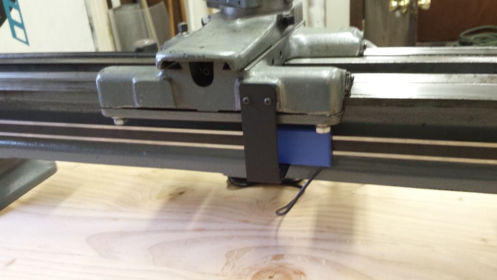
The finished installation. Now all that remains is to mount the actual readout.
I hope this is useful information for someone.
The new lathe bench is finished and waiting for the machine. It is built from Douglas Fir that I had on hand. I am fortunate in that I have a complete woodshop that allows me to build anything I can design. But you don't need a woodshop to build this bench. It can easily be built from lumber from the big box store.
The lathe bed assembly setting on the new bench. In this shot you can see the dollies under the legs. This allows me to keep the machine out of the way until the final setup. Then they will be removed.
Here you see the scale for the inexpensive DRO installed. I had this system waiting for an opportunity to be installed on the longitudinal axis. It just required drilling and tapping 2 holes in the bed.
My research showed that the scale needed to be isolated from the machine to avoid electrical interference from affecting the readings. In order to achieve this I made a pad to fit between the scale mounts and the machine from acrylic and put a nylon washer on the mounting screws.
Next the scale had to be trammed parallel to the travel of the axis on the face. This scale is quite flexible, unlike glass scales, so getting this perfect is really not necessary. I shimmed it to within 0.010" and that should be fine.
The next step is to tram the scale parallel to the axis in the vertical plane. The scale is not flexible in this plane so I trammed this to 0.001" This completes the installation and setup of the dro scale.
The next step is to fabricate brackets to connect the dro scale reader to the lathe carriage. This is the bracket, spacer, and screws. The bracket and spacer are aluminum painted black. To attach this to the lathe carriage I drilled and tapped 2 holes.
The finished installation. Now all that remains is to mount the actual readout.
I hope this is useful information for someone.