TB2 - flywheels

Home Model Engine Machinist Forum

Help Support Home Model Engine Machinist Forum:

This site may earn a commission from merchant affiliate links, including eBay, Amazon, and others.

kvom

Well-Known Member
HMEM Supporting Member
Joined
Jun 4, 2008
Messages
3,285
Reaction score
630
Brass arrived in the mail today. Thanks Dick!

medium.jpg


One extra for me to fubar ;-)
 
Looks like fun! It seems like every engine I've built the Flywheel was the first or second piece. I'm building a doodad right now and there is a brass pulley on it that I am thinking of programing some spokes to machine into it on the CNC at work:eek:)

Wes
 
I was over at my friend's shop this afternoon, where we faced all 9 of the flywheel blanks. After removing the saw marks on each face, the blanls are still thicker than the plans. I didn't mic all of them but the ones I did range from .45 to .51". Since the plan is to move the flywheels outside the bearing, I think leaving the extra mass would make sense.

Thoughts?

We drilled one to 11/64", but as my friend doesn't have a 3/16 reamer we didn't drill any others. We did try Bog's method of using 2-sided tape to hold the blank against the chuck, pressed via a tailstock center. This worked well, and I was able to get a nice finish on the perimeter.

Once any modifications are worked out, I'll try to make more progress.
 
I thought the flywheels were going to be the same thickness as the plans? That way they can be on the inside or outside of the bearing.

You having fun Kvom? I like making stuff on the lathe. But my favorite machine is the mill. Remember, if you have any questions, just ask:eek:)

Later, Wesley
 
I did a bit of experimenting with my "extra" flywheel blank last night. I made a 1-piece fixture out of aluminum rod. The first piece from 1.75" road I turned down so that one end is 1" in diameter and the other is 3/16", with the 1/75" in the center. The 1" end gets chucked in a collet and the flywheel is pushed onto the 3/16" end through its center hole and lies flat against the wider portion. The 3/16 nub is shorter than the thickness of the flywheel. The second piece is 1/2" rrod about 3" long. One end is center drilled and the other is turned down to another nub 3/16" in diameter. With piece 1 chucked and the flywheel attached, the second piece is pushed firmly against the wheel by the tailstock. There is enough pressure so that the edge of the wheel can be turned and the face turned as well. The diameter of piece 2 serves as a "stop" as it is the diameter of the hub.

The school shop provided a 3/16" reamer, so I'm good to go on the center hole.

I also put the wheel in the vise on the mill and drilled the hole for the locking pin. As the pin is specified to be 3/32" I used the next size drill, #41, to provide a bit of clearance. No problems in drilling. I need to locate some small set screws. 5-40s seem to ne scarce around here, but 6-32s should work too.

I still haven't heard definitively that the flywheels are to be outside the bearing and can be overwidth or not.
 
Hello, fellow Team Build flywheel maker!

;D

I did the flywheels on the last Team Build. Possibly my posts from that last build will help you, but there are lots of ways to go about it.

You'll need to decide what your tolerances are for the job. Remember, part of the fun of a TB is you're in manufacturing now. Can't just adapt other parts to fit yours--someone else is making those parts. So you have to build it to the prints.

A range of 0.450 - 0.510 is probably too much tolerance. You'll have to decide how to go about holding the desired tolerance on your flywheels. Not sure what this project needs. I was shooting for I thing < 0.004" as my tolerance on the flywheel widths. I bet this isn't quite that finicky. The other one really wasn't either, but it gave me an excuse to build a new tool and I seldom pass on that challenge.

You can refer to my posts to see how I got there:

http://www.homemodelenginemachinist.com/index.php?topic=1843.0

Best,

BW
 
I did read your thread previously, Bob. Reducing the width to .375 is not a problem, just seems wasteful.

Your wheels were 1" OD, so working with a collet was feasible. Since mine are 2" I need to use the 3-jaw for the facing/drilling/reaming. My little jigs for cutting the reverse side hub and the perimeter were done as an experiment. I'm sure 2-sided tape would work just as well.

I found some 4-40 set screws at Ace hardware. After I got home and checked the plan, I saw that the drill size for 4-40 threads is smaller than 3/32, so I will need to exchange them for 6-32s.

 
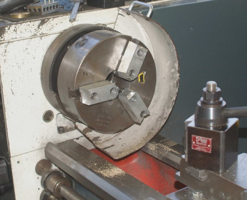
I continued working on the flywheels today in class. First, the instructor showed my how to set up and machine soft jaws in order to chuck the brass disks securely and repeatably. First we replace the outer hard jaws with the aluminum jaws:

large.jpg


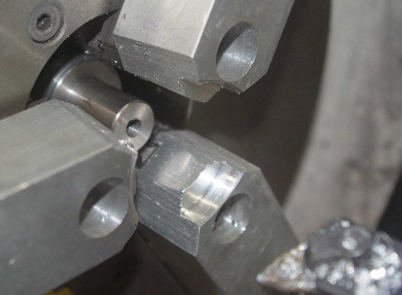
Next the jaws much be machined to form a pocket that will clamp the flywheels securely as well as allow sufficient material to extend beyond the jaws:

large.jpg


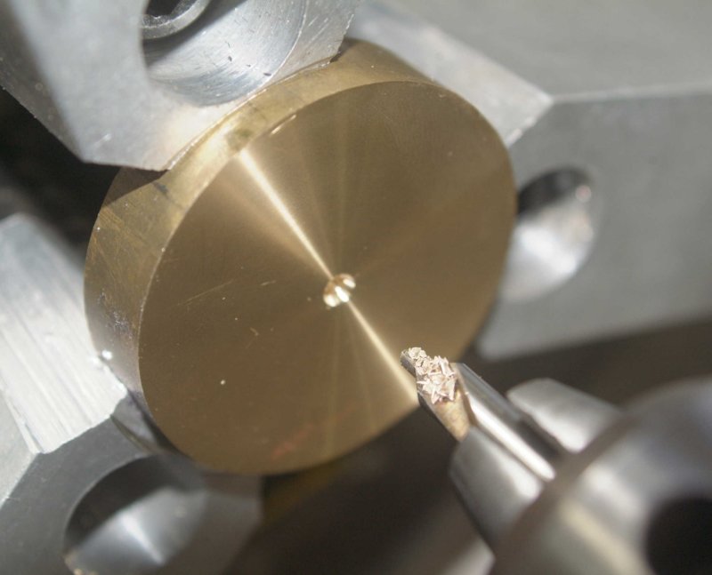
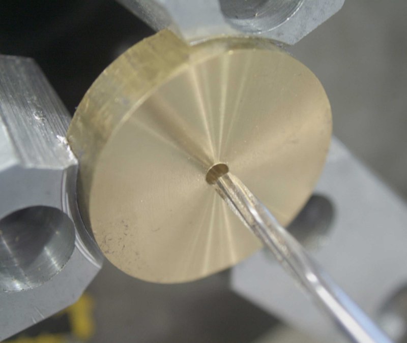
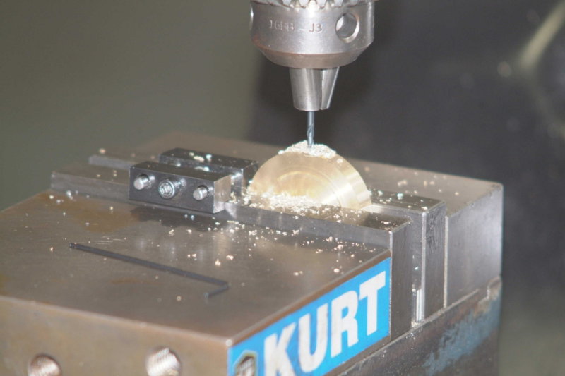
Now we can chuck a wheel and center drill it:

large.jpg


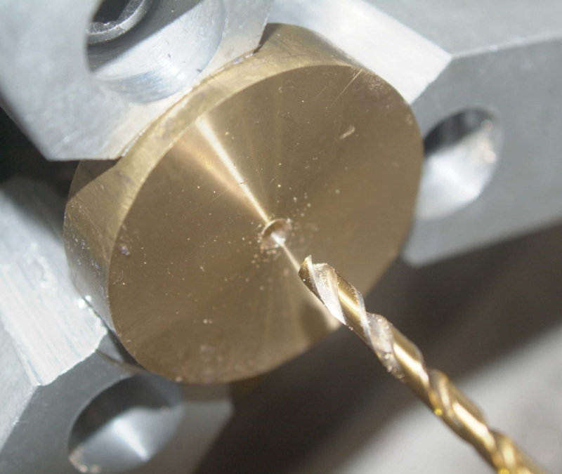
Then drill 11/64 hole (1/64 below final 3/16 size):

large.jpg


Then 3/16" reamer to obtain the "close fit" described in the drawing:

large.jpg


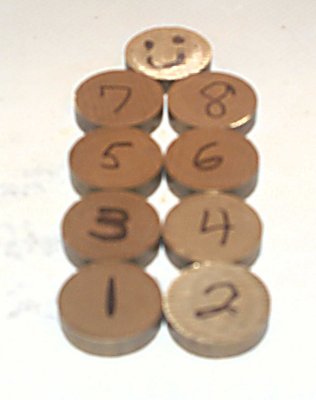
Once all 8 wheels were drilled, I then faced each on one side to a thickness of around .390", and then made a small chamfer on the hole. The chamfer will aid in mounting a fixture I made for eventually turning the edges.

When all 8 wheels were faced on one side, I faced each one to final thickness on the other side, generally within +/- .003". Because the boring tool used to cut the jaws has a slightly round tip, the disks do not chuck as precisely as possible. To get better tolerances it would be necessary to use a second boring tool to undercut the inner edge of the pocket.

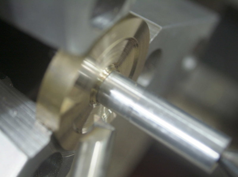
Next I chucked a wheel and added a small aluminum fixture I had made previously. It has a 3/16" nib that fits the flywheel hole tightly and a 1/2" diameter that matches the hub. Te other end is center drilled and pressed in by a live center. I then mounted a boring bar that I had ground to cut the inner recess.

large.jpg


I was able to perform this operation on only one of the wheels. Next time I hope to do the other 7, then turn the edges and drill/tap the vertical holes.

The soft jaws definitely made this a "production line" type of work. Definitely worth the couple of hours it took to get them set up.
 
Finished turning all 8 wheels. Next week I should be able to drill and tap for the setscrew. Then they will be ready to go.
 
Got the holes drilled for the set screw.

Since pin is 3/32 I used next largest drill size, #41. Then drilled and tapped for 6-32 set screws. Using a stop on the vise made the machining relatively fast, as I had to indicate only on the first wheel. Then it was just a matter of chucking in the vise against the stop, then center drill, drill hole, drill partial for set screw, then hand tap.

Once I get some 3/32 drill rod or equivalent and cut to size these will be ready to mail out.

large.jpg
 
Back
Top