2024 Florida Flywheelers Show

Home Model Engine Machinist Forum

Help Support Home Model Engine Machinist Forum:

This site may earn a commission from merchant affiliate links, including eBay, Amazon, and others.

raveney

Well-Known Member
Joined
Mar 16, 2018
Messages
254
Reaction score
746
Location
Central Florida, USA
I go to this show every year
Its overcast and mid 70 F today here in central Florida. Mostly real hit and miss engines, antique tractors etc. Very useful to me to see real size ones. They have an operating 1916 Case tractor which I used as a reference when building the well known Rudy's Tractor model. I have a build link. This year I want to focus on vertical engines and screen coolers and will share some pictures of today's trip.

https://floridaflywheelers.org/events/

map.pngScreenshot 2024-01-19 080212.png
 
The showgrounds were a bit muddy yesterday, but clear skies and pleasant low 70's. Two items caught my attention early on that I thought worth sharing.

I never noticed that some of the hit-n-miss engines had split hub flywheels like this treasure of a find. A Fairbanks Morse that some one is taking home from the show. I love the rust/patina finish.

Fairbanks Morse split hub flywheel.jpg20240119_103030.jpg
Another oddity is this Aermotor. The owner wasn't present to discuss it but had some information on a sign. Looks like a hybrid water cooled hopper engine but with increased surface area for convection cooling. The advertisement warns that this is the only time the ad will appear.

20240119_122744.jpgAermotor.jpg20240119_122712.jpg20240119_122720.jpg
 
You are welcome Mr Greentwin,

They have several shows, all in the wintertime.

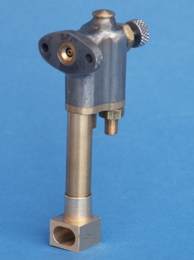
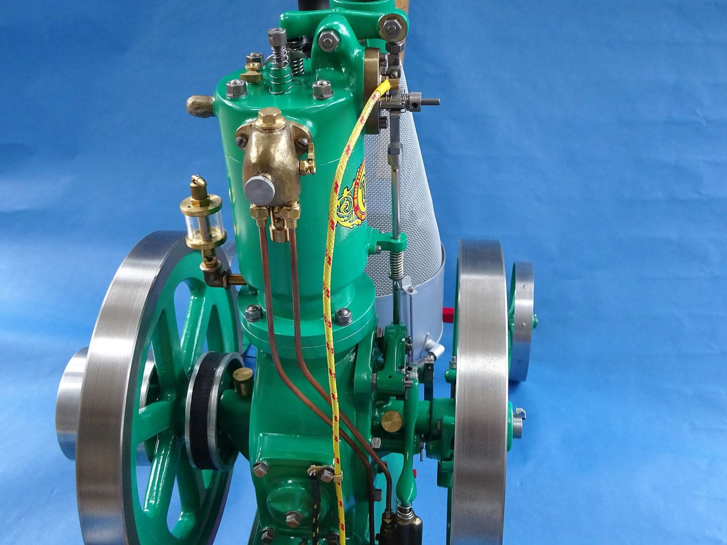
It would be challenging to replicate in small scale. I spotted the same type on an International Harvester engine also. The gentleman that owned told me it predated the Famous. it was neat because of the intake/exhaust actuation also. Started right up for him cold also. I'd like to build one of these vertical single cylinder hit/miss engines from scratch so I took a bunch of pictures. I think the fuel mixer is cool also but not sure what is inside it. It has a positive displacement pump with a supply and return going to/from the copper fuel tank. The brass knob is a needle valve as I was told.

Anyone have a cutaway drawing?

20240119_104114.jpg20240119_105739.jpg20240119_110147.jpg20240119_110239.jpg20240119_105746.jpg20240119_105759.jpg

beautiful survivor to see down here in the South

 
According to the IHC catalog, the bowl on the carburetor allows a fuel tank to be located at a level far below the engine.

The bowl is kept full with the pump, with any excess draining back to the tank.

Pretty simple arrangement.

.

Imag5e10.jpg
 
Green Twin,

Thanks for posting the info on International Famous engines. I'm currently building a model of one and the pictures are very helpful. International claims this is a simple engine but its features make for some interesting machining challenges like speed control. The design indicates a high quality engine.
 
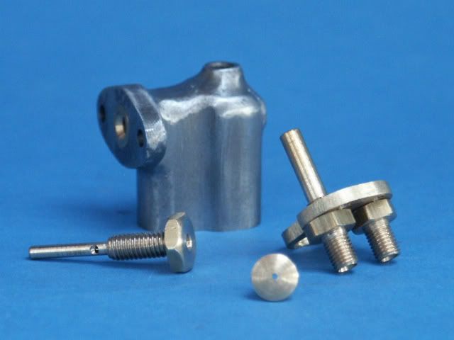
The Vertical R&V uses a similar carb as the IHC, neither was too hard to make.

PICT0163.jpg


DSC03485_zpslgl4qpt6.jpg


As for the split flywheel From a machining perspective it would be best to cut the slot after boring but core the bolt hole if you want to put a bolt in it. Some models use a dummy bolt others like the small VJ Monitor kits come with the hole in the casting.

The Old Blackberry models1/5th IHC design is not too bad but the fuel and water pumps needed to be redesigned to look right (useless castings). There is also a set of drawings for a larger one that does not use castings which would be worth getting if you want to scratch build one. This was done by a guy from these OnderStoom plans which are 1/3rd scale, attachment shows it before painting.

https://website.onderstoom.nl/product/special-no-11/
 

Attachments

  • Toby IHC.jpg
    Toby IHC.jpg
    118.3 KB · Views: 0
Last edited:
According to the IHC catalog, the bowl on the carburetor allows a fuel tank to be located at a level far below the engine.

The bowl is kept full with the pump, with any excess draining back to the tank.

Pretty simple arrangement.

.

View attachment 153205

so does the bowl/chamber have a built in weir or dam that allows some fuel to be inside the mixer as an inlet to the needle valve and the overflow returns to the tank under gravity?
Fuel Mixer concept.png
 
Yes, that is why there are two pipes to the bottom of the carb. One is pumped up from the fuel tank within the base and the excess runs over the wier and done the other pipe back into the tank. Fuel level in carb is just below needle valve so it won't flood but easily drawn up on an hit stroke.

The 1/5th Scale model is quite small so would have been hard to replicate any cored internals to the casting so the design just has fuel going into a chamber at the bottom and overflowing back down a stand pipe. That casting is only about 1" tall.

PICT0135.jpg
 
Thank you very much Jason B,
I will follow your lead on the overflow pipe versus weir when it comes to building that style mixer in the future

here are some images of a very fine Root & Van der Voort engine I saw at the recent show happily running while making delicious ice cream. The trailer (axles and wheels) looked pretty authentic also.
20240119_132708.jpg20240119_132649.jpg20240119_132802.jpg20240119_132814.jpg
 
Spotted a IHC air cooled famous vertical engine that would make an interesting model. I liked the curvy base and finned cylinder. It has small cylindrical fins on the head that look like those stalagmites that are formed in caves. Also noted the valve goes through an exhaust elbow that is separate part like a thermostat housing. Fuel mixer looked to be stamped sheet metal. Belt driven fan on the left side. Seemed like a good idea for a portable engine to pump water for cattle or such.


20240119_122006.jpg20240119_122025.jpg20240119_122040.jpg

The gigantic Snow Engine is a big attraction at the show. 1914 4 cylinder double acting engine with 40,000 cubic inches. It pumped natural gas from gas wells to pipeline customers


20240119_131137.jpg
 
It is quite an attractive engine with the soft curves of the crankcase. The valve as part of the inlet or exhaust elbow is quite common The ball Hopper Monitor I made has similar as does the horizontal Perkins

Oddly enough on one of the Facebook groups there has just been some discussion over the gas engine in this book. It suggests modifying stock pipe elbows to take the valves. Not sure there would be much in the way of valve guide length! There are a few anomalies and missing details in the article but it would make an interesting project with a few tweaks so it is more likely to work.

https://archive.org/details/boysbookofengine00coll/page/236/mode/2up
I also noticed this engine last night, despite what is being said here about the lack of gas engine kits here is a newly offered one in the form of a vertical air cooled Perkins. Not sure if it has any link to the Debolt offering of the past.

http://www.theengineersemporium.com/catalogue-pages/petrolengcastingkits.html#
 

Attachments

  • IMAG2521.jpg
    IMAG2521.jpg
    819.2 KB · Views: 0
  • DSC01422.JPG
    DSC01422.JPG
    4.7 MB · Views: 0
Last edited:
Fascinating bit about the hot tube igniter in the Boy's Book of Engine Building. Such a simple idea.

I guess I never believed the "pilot" flame that keeps the tube hot would scale down to model size (stay lit). Has anyone you know of attempted to use this feature?
igniter.png

thank you for the link to the Emporium castings. I had given up all hope on commercially available vertical engine plans
 
I've a couple of hot tube engines, Should be a shot down the chimney of both somewhere in teh videos so you can see th etube glowing. Tubes are 3/16" stainless steel drilled 1/8" so quite thin wall. Moving the burner so a different part of the tube is the hottest adjusts ignition timing.


Attachments

  • 20190203_084053.jpg
    20190203_084053.jpg
    2 MB · Views: 0

Latest posts

Back
Top