Home Model Engine Machinist Forum

Help Support Home Model Engine Machinist Forum:

This site may earn a commission from merchant affiliate links, including eBay, Amazon, and others.
When I wrote previously, I thought you had done this end flange prior to machining the gauge plate base, and crank main bearings. Thus making the gauge plate was a way to translate the bore/flange machining for the cylinder to make the bearing alignment. I didn't appreciate the gauge plate base was simply a way to make a method of clamping the base casting to the right-angled plate.
I feel you missed the point about my Vee-block idea.
The Principle axis of the engine is the Crankshaft. By "Principle", the axis MUST be identified, and secured by machining very early, so most other critical machining can be taken from this axis.
Of course, to permit repeatable setting-up, the underside of your casting had to be machined first. But that is NOT a running / working surface except for a reference to "other machines"etc. when finally mounted.
The Secondary main working axis is the cylinder-bore axis.
Your odd brass and aluminium insert is a little "weird" (in my head) as you set it into a casting, (Not sure how or where it relates to the casting?) then you precisely aligned this to the Quill axis before boring for the cylinder to mate. I am not sure what all this is really doing...? It seems an Imprecisely fitted bar is being precisely aligned, so the imprecision exists in the machining of the casting?
My sequence (Because that's what I was taught in the 1960s when boring cylinder blocks!).
1: Ensure the underside of the base casting is flat with a reasonable alignment to the CAST bearing and cylinder mounting holes. - This is where an appreciation of Datum alignment is required to understand the castings are NOT perfect and often need compromise, if inadequate machining allowance is not provided. The base grinding set-up is where your brass/aluminium bar could help, but scribe lines on the casting work fine for me. I assume the casting is about right, I.E. plus-or-minus 1/8" from where everything should be. "By eye" marks are better than that, so are adequate to decide where the casting is mounted for the flat underside to be ground. - But you have done all that.
2: From the flat base surface, the bearings can be positioned and machined to form the PRIMARY DYNAMIC datum. This is used to mount the base casting on the precisely set-up angle plate. - But with "freedom" to re-position to the Crank-axis.
3: From this datum, the bore can be set: at Exactly the correct distance for the bore axis to be to align with the Primary dynamic datum. I.E. if the bearings were set at 1.457 INCHES above the flat base underside DATUM, then the bore shall be centred EXACTLY at that same dimension. That will centre the bore on the crankshaft axis.
4: With test bar in the bearings, the test bar can be set in Vee-blocks, and the test bar used to clock to ensure it is exactly perpendicular to the Quill. (In case your Vee-blocks are NOT the same size, muck anywhere, imperfect machine alignment, etc.). THEN the base casting can be securely clamped to the right angled plate surface.

You can still use this alignment to eliminate all the TINY errors that are in-built from the machining of all the components by using this as the set-up for BORING the cylinder. All the other stuff is holding the parts together. This BORING to be perpendicular to the crank axis is the PRECISION that makes a good engine.
Sorry if my explanation is a bit crude - Boring even?
If I am wrong will any experts tell me where I am wrong, as I appreciate life-long toolmakers know best - and my friend and mentor is unfortunately past-it now.
j is doing a really careful job, being precise in setting everything to DTIs, etc. But I "worry" that following the wrong sequence or datum can lead to an "Imprecise" engine that disappoints - and we all want this to be the best he can make.
All is not lost: The final boring to the crank axis is the key.
K2

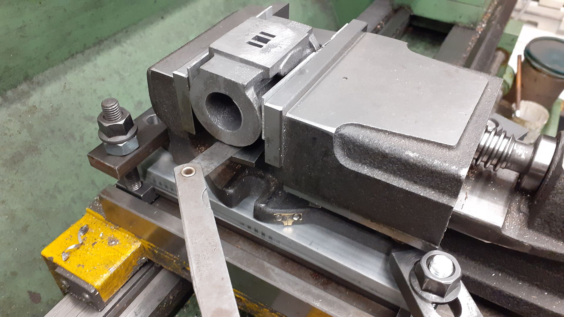
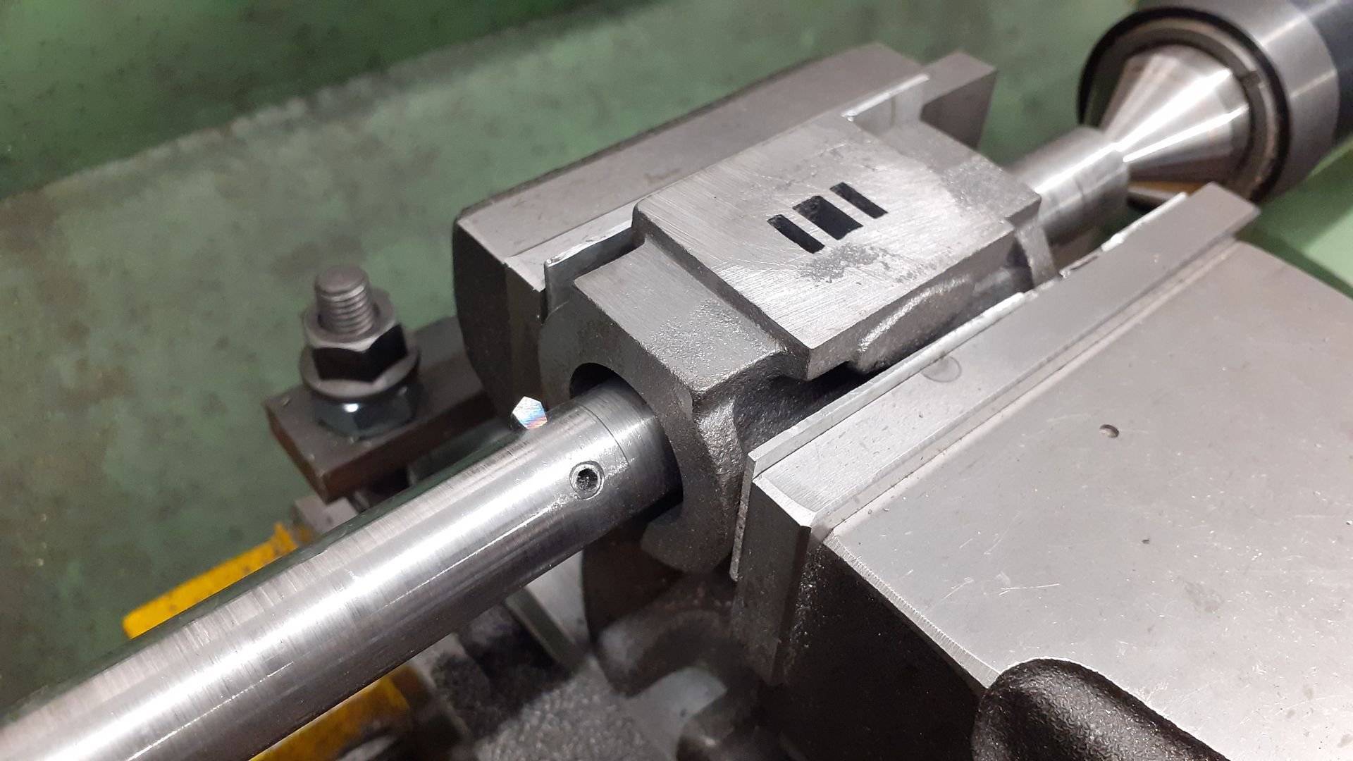
My brass bar was used to ensure that the casting was reasonably straight and that the middle of the journals was in alignment with the center of the cylinder flange. Obviously from a casting it can never be exact but there is little room for plus-or-minus 1/8" on these castings. Not in the middle of the flange webs will see catastrophic results when the flange is bored through.

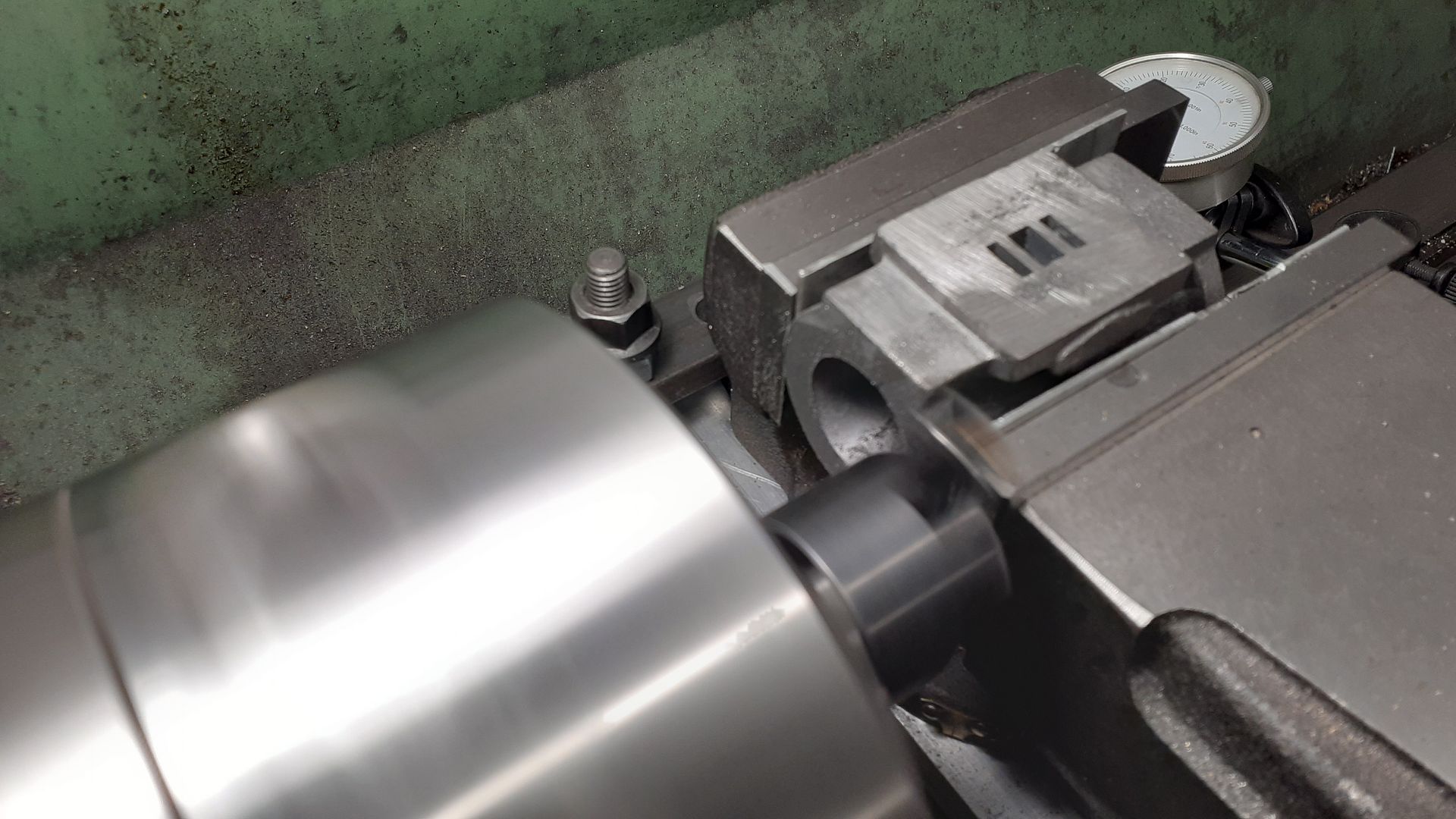
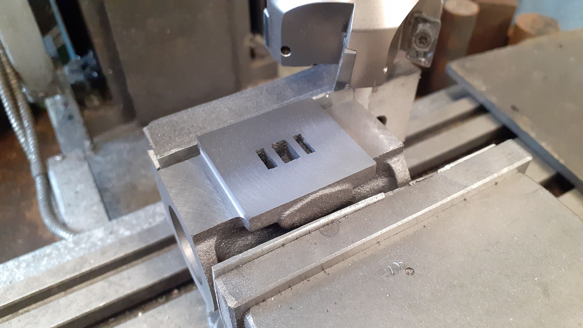
Now that my fixture plate is securely in place all parts will be machined with reference to the primary datum which is the edge of the plate closest to the bearings. I can't use v-blocks until the bearings are fitted and bored. Granted I could have waited until then until machining the flange but that ship has sailed now and had sailed long before you made your suggestion.

As you say, I could easily grind the flange face using v-blocks and an angle plate if things do not go well. That is always an option. With a bit of luck my bearings will be aligned with my reference and that won't be a problem.

There are many ways to skin a cat precisely.
 
We are not talking of skinning cats. You need to have an open mind, but when it comes to critical alignments, the bore must be truly square to the crank axis. You appear to me to be coming at it indirectly via a bolted on plate. I am proposing a direct set-up from crank axis to cylinder bore (not flange face), that avoids acumulated errors of a number of interfaces.
As it stands, you are set-up to have a job that is less than perfect, IMHO. Luck does not exist when making good engines. Good set-up strategy helps though.
You can still make the cylinder, fit it to the base casting, then set-up from the bearings with a straight bar instead of crankshaft fitted in the bearings, in order to finish boring the cylinder. That way you'll recover from any accumulation of error in the various set-ups so far.
But my advice is just that. "Good luck" ( I don't believe in luck but you seem to need it) with whatever way you choose to make the engine.
No problem to me, I can only advise.
K2
 
Last edited:

Part 4 - Bearing Journals​

Next job was to mill out the bearing journals. This involved setting up the sole plate horizontally. To minimise any errors I bolted my fixture plate directly to the mill ways and aligned it carefully using the end flange as a reference. This took considerable time as I was using a 'tenths' indicator. I could not get it any better than 1 tenth - 0.0001". So hopefully that will be good enough!

IMG_8982.jpeg


I used the diameter of the end flange to locate the vertical centre of the bore. This and the end of the flange is where all dimensions are measured from so it is important to get this as accurate as possible. To double check I machined up some aluminium as a tight fit in the bore and machined that down to my zero height. I removed this and checked against it's diameter only to find I was out by 0.001". This was corrected in the DRO.

I was worried that tapping out the plug may have affected my alignment, so I double checked that once more and made sure everything was where I expected it to be.

Using a brand new 8mm carbide end mill I took my journals down to the centre of my bore. Then I made the slot through the middle. This was a simple matter of machining almost to depth before expanding the width before making a cleanup pass to final width and depth. Creating a new coordinate system in the DRO which is centred on the bearings really helps at this point.

Then it was a matter of machining the sides of the journals before drilling and tapping the four 5BA holes.

IMG_8988.jpeg


The next task was to take the crosshead slide down to it's finished height of 5/8" below the cylinder axis.
Once this was done I drilled and tapped the 6 holes for the crosshead slide guides.

IMG_8990.jpeg


Once that was all done I could tear down the setup and mount the bedplate at 90 degrees so that I could finish the mounting boss for the valve guide. This proved to be quite tricky as my hobby mill is not large and it took me a couple of attempts to find something that would satisfy all requirements.
IMG_8991.jpeg


Last job was to cleanup the valve guide flange. This was problematic as it didn't quite have enough material available. I took it down below spec as it should not be too hard to either increase the thickness of the mating part or to introduce a packing shim.

IMG_8992.jpeg

So finally that is pretty much it for this casting. It doesn't look like much but it really was a lot of work. There is one more hole to add which bolts the bottom of the cylinder in place, and I need to spot face the cylinder bolts, but those jobs can wait for now.
 
It's coming along well

I don't find dowels are often needed. Provided you do all the main machining with out removing the casting from the machining plate then the same edge of the machining plate can be clocked true for each setup.

I also don't drill tapping right through plate and casting, etc, I just note the DRO readings when drilling the casting and use them to place the holes in the plate

The theory of the Vee blocks is OK but a lot of hobby mills simply won't have the head room to allow the casting to stand on end and get a boring head/bar into place. That's assuming the tram is true.

This is my well used machining plate, I've lost count of the number or open crank IC and steam engine castings that have been on that but they all run so must be OK. its 10mm thick 100 x 300

20240611_095126[1].jpg
 
It's coming along well

I don't find dowels are often needed. Provided you do all the main machining with out removing the casting from the machining plate then the same edge of the machining plate can be clocked true for each setup.

I also don't drill tapping right through plate and casting, etc, I just note the DRO readings when drilling the casting and use them to place the holes in the plate

The theory of the Vee blocks is OK but a lot of hobby mills simply won't have the head room to allow the casting to stand on end and get a boring head/bar into place. That's assuming the tram is true.

This is my well used machining plate, I've lost count of the number or open crank IC and steam engine castings that have been on that but they all run so must be OK. its 10mm thick 100 x 300
It's especially tricky to do the bearings first as pretty much every feature on the engine is dimensioned from the cylinder flange. It's hard enough to decipher the expertly hidden dimensions on this drawing without having to work backwards! If it was good enough for Tubal Cain, it should be ok for me I think.

Thank's for your comment. That's a wonderful fixture plate. I hope mine ends up looking just as well used!
 
Creasy, FYI, I found the valve rod guide to be problematic, nearly impossible to get its bore lined up perfectly with the valve rod, I used shims above and below the screws that hold it onto the boss in the base in order to tilt it into alignment, but if I ever have to take it apart and re-assemble it, I'll probably leave the shims out, bolt it down tight, and "tap" it into alignment as the bronze used in Stuart castings is very soft and malleable (at least the old castings, if they've recently changed to brass that could be different).

Also, I did not use a machining plate, but dang that's brilliant, and I wish I had the brains to have thought of that :) !!!
Thanks very much for that tip. I have been worried about that forever. It seems like a crazy design. Especially if you consider the steam chest would most likely have a gasket. Problems seem to be inevitable.
 

Part 5 - Reverse Counterbore​

The back side of the cylinder flange is very curved and I wanted to make sure that the nuts that hold things down have a flat surface to press against. I could not use a normal counterbore because the bearing journals are in the way so I needed to make a reverse counterbore. I have noticed that many builders either ignore this issue or in one case I found they had used a very narrow washer below the nut. I think that is quite a good solution but really I think best practice is to counterbore the flange and let the nuts do their job.

After failing miserably I found this very useful article about the subject: Making Counterbores from Drill Rod in the Home Shop

I chose a simple design with two cutting edges and a removable alignment shaft held in place with a 3mm grub screw.
IMG_9029.jpeg


I used my cordless drill and It worked very well although it did leave a mark on the side of the casting in one spot. I have fixed that with some jb-weld so it should not be a problem after the paintwork is done hopefully.

counterbore-1.jpg
counterbore-3.jpg
 
Last edited:
Not an unusual way of making a spot-face on a reverse side of a job, but more usual to align by using the milling machine. But surely better than the cast surface., for the nuts to impinge. I should insert a plain washer beneath each nut. (Possibly brass instead of steel?). This should avoid local stress concentration and subsequent deformation of the cast iron where it contacts the nut, which can cause slackening of nuts if the metal relaxes in service. And use of a spring washer can also apply some axial spring to help maintain contact pressure. (Belville washers are best for this application, but I doubt you will find them so small.). As it is a model, it is "unlikely" you'll have a problem, but good to make "unlikely" into "never".
I well remember how cast iron and aluminium cylinder heads always used to show "bruising" where the head bolts/nuts etc. had been tightened down without proper washers. A very good reason to re-torque after a few hundred miles of running-in!
A tip. If you ever need to "stick" a washer in place while assembling, you may find a small dab of (breakable) loctite will be adequate. To prevent the loctite then glueing the nut to the threads, use a greased thread. Disassembly then is easy and washers stay nicely in place for the next time. Loctite on some threads that may be re-torqued (or need re-tightening) is not a good idea, as the loctite will give the wrong torque when re-setting the fixing. Correct torqueing of fixings should be done on free-running threads, clean and lubricated for the most accurate and repeatable settings. Usually joints are torqued where special attention is required to achieve a high torque, or to PREVENT over-torqueing, as well as to get consistency of applied torque across a series of fixings. Models rarely see a torque wrench. Torques are so small we all rely upon "feel" - and sometimes (I) get it wrong. My next tool purchase should be a low range torque screwdriver, that takes sockets, hex bits, etc.
https://www.ebay.co.uk/itm/16601263...d0JtH04lkxln8oKztFvEjki6E=|tkp:BlBMUPCzns6EZA

K2
 

Part 6 - Boring the Cylinder​

After the usual fettling I started out by cleaning up the casting in the milling machine to give myself some good reference surfaces to work from.
I started by milling the port face.
IMG_9030.jpeg


Once that was done I used my grinding vise to clean up the ends. I did this because I trust my grinding vise much more than I trust my mill vise to be 90 degrees to the bed.

cylinder-1.jpg


This probably would have been fine but I couldn't resist putting it through the surface grinder as well just to make sure everything was parallel and flat. The ends of the cylinder are still oversize so they will need to be machined again but that will allow me to make sure the ends are perpendicular to the bore.
cylinder-2.jpg


To figure out the alignment of the bore I made a fixture that allowed me to clamp the cylinder between two large washers. One of the washers was the same size as the outside of the cylinder and this allowed me to align the fixture with the center of the cylinder that best matched the outside of the casting. The ends of the fixture were drilled out with a center drill so that I could hold everything in the lathe between centres.
IMG_9075.jpeg


I used the vertical slide to hold my grinding vise and used this to clamp the cylinder by gripping on the valve chest. This reduced the chance of any deformation effecting the bore. Once everything was aligned and firmly clamped down I could remove the fixture allowing clear access to the bore.

cylinder-3.jpg


I used my boring bar held between centers to machine out the bore. The boring bar came with my lathe and I have always wanted to use it. Unfortunately no matter what I tried it chattered and did not generate a great surface finish.

cylinder-4.jpg


I decided to cut my losses and try the milling machine. I didn't have much in the way of boring bars that was suitable but I did manage to cobble something together from an old lathe tool. Of course that too chattered pretty bad but it was better than the lathe.

cylinder-5.jpg


Back to the drawing board once again, I made my own boring bar from some very sturdy 4140 bar. I milled a pocket to hold an insert and experimentation showed that the sharp inserts designed for aluminium with the mill running on its very slowest speed would give me a reasonable finish.

cylinder-6.jpg


So finally I have a cylinder bore. Well not really as I still need to clean up the ends, drill lots of holes and add an exhaust port. So plenty of fun still to be had. I filmed most of the work described above and I edited it into a small youTube video. My normal editing program is iMovie but for some reason it did not like this footage and would not export the final file. I reset everything and re-edited everything once again only to find the same problem. Finally I tried a different editing program (Davinci Resolve) and went through the tedious editing process for a third time! Third time is a charm though and that worked. So I don't expect I will ever be troubling iMovie again. Very sad because it is such a nice program to use.

The photo below shows the final surface finish which is a little disappointing after so much work.

IMG_9077.jpeg


I am currently well advanced making an expanding mandrel which (fingers crossed) will allow me to lap the bore as well as turn the cylinder ends to final size, thereby ensuring they are exactly orthogonal to the bore. Hopefully this will cure any surface finish issues.
 
congrats on the progress, the #9 might be my favorite !

in my experience, surface finish when using boring bar in mill is result of tool bit cutting angles (you need to rotate the tool until it has a slight rake), and if the tip is not razor sharp then also depth of cut. counter-intuitively for me, if there's the slightest amount of dull edge to the cutting bit then a shallow finishing cut will result in chatter and you're screwed, polishing out the chatter will result in an oversize bore (not much of an issue with a steam engine, but can be for an IC engine), and that polishing requires a lap, and you might not be prepared for that, so the adventure continues. :) !!!
 
Cast iron = cutting speed!, this is totally different to brass, free cutting steel, etc. So SLOW, SLOW SLOW! (I did dozens of re-bores on Saturdays and summer holidays as a teenager. Then honed them the last 0.002 in to size. ).
Boring a 3 inch bore we used about 60 rpm on the boring bar. So a 1 inch bore is still only 180rpm... MAX! - and follow other instructions above.
K
 
Well it turns out that my boring bar is actually a genuine Myford accessory most likely purchased by my lathe's original owner. I bet I am the first person who has ever used it! I won't give up on it just yet. It's poor performance must have been user error.
IMG_9079.jpeg
 
Maybe just a very long bar when you really needed a shorter one - to cope with the cut you were trying to make?
A "natural" problem with castings is the hard surface and soft metal beneath. You need the tool to be the correct ground angle for cast iron, and very well supported (a stiff set-up) to cope with the size of cut and feed rate to break the crust/hard surface. Added to the SLOW speed needed, really tests a poor set-up.
A long boring bar is hugely more flexible than a short one, between chuck/headstock centre and tailstock centre.
Having made the boring bars to suit, I always bore my cylinders in the Milling-Drilling machine. So effectively the bar (as large as I can get in the bore with fly-cutter) is held in a collet in the Quill, and is unsupported at t'other end (cutter end). I just use a suitable size of ground steel bar and drill n tap to take a fly cutter. That way I can readily make a longer or shorter bar, of suitable diameter, to suit the cylinder in question.
SO your set-up is better, with tailstock centre, but only if the bar is short (stiff)/ However, it needs to be ~ 3 x the length of the bore, so it can traverse the cutter fully and clear in both directions (both ends). - but will be stiffer than mine if length is kept as short as practical. As you had chatter (caused by speed and some springiness in the set-up) I reckon you were cutting too fast, possibly with tool ground unsuitably? - and the long boring bar was a nice spring to resonate with the cutter intermittently cutting and relaxing off the surface?
Does you lathe have adequate torque below 200rpm main-shaft speed? - I should be that slow to break the skin and cut the cast iron properly! Limited to 0.010in cut max, fine feed and sharp pointed tool with a tiny relief radius at the point. (hand stoned).
Any other advice Gents and Ladies?
K2
 
In my experience the finish is determined by rigidity of the between centres bar and cutting speed. For a 1inch bore I would use at least a 3/4inch bar or ideally a 7/8 bar with a rounded cutter and the slowest feed rate possible. I always finish up with close to a mirror finish. I adjust the cutter by holding the bar across 2 V blocks and using a height gauge on a surface plate. There are fancy adjusting methods (see Hemmingways site for boring bar kits) but I find the simple method works for me.
Mike
 
I use a between ctrs boring bar quite alot for cylinders. You look to have quite an overhung setup with the vertical slide, vice and work sticking well out of the vice. It would be better to either pack the job up on the cross slide or if you want to use a vice then mount that onto the cross slide with packing to bring the cylinder upto height. This is a Stuart 1" x 2" cylinder as found on many of their models. After boring flycut or face mill the piston rod end true to the bore without changing the setup. You can then move the vice with casting still in it to the mill and machine the portface so all is square and true.

I'd be running about 350-400rpm with a 1" between cts bar on a cylinder the size of the No9. Free hand ground cutting tool from old Carbide milling cutter shank

20230120_161445_jLsY29oj5UdG3gHdZrT8DB.jpg


20230120_164544_3yrnaSCKD4dVa8kYGtbmyM.jpg


20230120_165708_tj3Gpo5me9dKFDZR32AVM7.jpg


20230121_083630.jpg


Bit of an old video as I can't find a more recent one but gives the idea, that is a 1" bar, 400rpm, fine feed.

 
Last edited:
Nothing wrong with a long bar and often needed to give enough run out at the end of the bore. Main thing is that it is not too slender so use a decent diameter This one is 35mm dia x 625mm long, again running carbide but a CCGT insert in a microbore holder, cutting a 40mm bore at 525rpm

The casting is 305mm long so you do not need a bar that is 3 times the bore length, just over 2 times will do. Infact on larger bored I have allowd the rotating tailstock ctr to enter the bore so the bar can actually be shorter than 2X

 
Last edited:
Hi Jason,
A problem I have experienced, when machining various cast iron and cast steel parts, is that there is a critical cutting speed at which the particular material will cut. as soon as the speed exceeds that point the cuter slides on the surface - especially with fine finishing cuts - and the cast iron actually grinds the tool edge away! - But I use Steel tools for ease of grinding my own. Carbide inserts will be fine at higher speeds than I use. Also, when breaking a glaze, or cast skin, I find I need a careful large cut and low speed so the tool gets beneath the hard skin. I guess your video shows (and sounds) like you are on the grey cast iron surface that cuts nicely. Once into the fine grain core of castings they do machine very easily, and do not require the torque needed to "break the scale" - which can be tougher to machine than mill-scale on hot rolled steel (Black bar).

To determine the speed at which the tool "slides and is ground" I did a test - facing a difficult piece of material - as the cutting speed varies with diameter. It was clearly, and repeatable, a specific surface speed for that cast iron. On previous geared lathes I always used the back-gear for flywheels and larger diameters of parts, and had no problems. (6in diameter with a 1/4HP motor). But my "modern" variable speed "1HP" lathe does not have that luxury, and consequently has very low torque at low speeds (80rpm main-shaft) so with only a low torque (6.4% of full torque!), cutting the scale with a large cut and needing the low speed was problematic.
I am glad you can bore as well and easily as you are demonstrating. With a more powerful or geared lathe many problems do not appear, that are only seen with certain machines. My 1/4HP gearing was about 30:1 from the motor, so equivalent to about an 8HP equivalent of my 1HP machine, with the turn-down torque drop I have from the variable speed board... "Ya pays ya money..." etc. And I bought a small "hobby" lathe (3ft long), as I don't have space for an industrial job. I should really convert the idler puller for belt tensioning into a 2:1 or better intermediate idler to improve low speed torque. (Another job for the list).
1721887350534.png


I guess you have something a little bit larger?
JCreasey doesn't describe his tooling - lathe speed, power, torque, or tool cuter ground shape in post#31, so without that detail, we can all simply describe " how we did it" and any problems we have experienced, to help those that (like me) are still learning. Good to have your expertise Jason! I always enjoy your advice.
K2
 

Latest posts

Back
Top