Stuart No. 4 build

Home Model Engine Machinist Forum

Help Support Home Model Engine Machinist Forum:

This site may earn a commission from merchant affiliate links, including eBay, Amazon, and others.
Nicely done Simon and glad to see you back at it. It looks like it is starting to take shape now. I will be here till it is complete.

Don
 
Nice work on the castings Simon, just finding a few more projects to watch and haven't seen a Stuart No. 4 done before, keep up the good work.
 
Got some shop time in today, since it's a holiday!

First up, I marked out and drilled the bolt holes in the standard:


and drilled and tapped the soleplate for these bolts. I had left this until now because I was worried about getting the alignment right, and wanted to be able to assemble the crosshead and conrod with the crankshaft to make sure everything lined up. Luckily things fitted just fine.

Next up was the crosshead bolt (which I called a pin earlier, but the plans refer to it as a bolt). This started as a bit of stainless from the scrap bin; the first part is a simple turning job, taking care to get a nice 1/4" fit to the conrod and crosshead:


Checking the fit on the conrod:


It's important here that the nut will bear down on the shoulder of the bolt, rather than the conrod arm, otherwise the nut may loosen when the engine runs. I have a bit to take off the yoke of the conrod by filing, but it's close.

Then it's threaded 2BA, with an undercut at the end of the thread so that the nut seats nicely:


I flipped it around, held it in a 1/4" collet, and carefully parted off the excess:


then turned the head. Almost done:


I'm using temporary fasteners for everything so far, hence the ugly nut. Oddly, the fastener set that came with these castings has been blackened. I'm not sure if Stuart shipped them that way for a while, or whether the previous owner did it. Or maybe it's just from storage?

There's one more bit on this bolt/conrod to do, and that's a 1/16" pin that prevents the bolt from rotating. This sits right on the edge of bolt's shaft. Here I've drilled the corresponding hole in the conrod:


I took care with the setup, using an edge finder on some 1/4" rod situated in the hole, then offsetting to find the center of this pin. I was worried about the teeny drill wandering into the main hole, but it was OK.

Without changing the setup, I then dropped the crosshead bolt in, tightened the nut on the other end, and clamped it down to prevent it spinning. Then I could drill a matching 1/16" hole for the pin, and guarantee alignment:


Final crosshead/conrod/bolt parts:


I need to find a 1/16" pin somewhere. Any ideas?

After some more fiddling to fit the conrod bearing to the crankshaft journal, I was able to put everything together and give it a spin on the lathe. It's all pretty tight, so needs a good bit of running in:

[ame]http://www.youtube.com/watch?v=5z6fSfN6XRc[/ame]

(Sorry about the crappy vertical video.)
 
Simon,

Nice work - as usual!

For your 1/16" pin, I'd use a piece of blunt 1/16" drill shank (I tend to keep them in the scrap box, rather than throwing them out for just this type of situation) - you might need to anneal it to allow you to cut/ file it.

Regards Tom
 
If You want to keep it hardened, You can cut it with a disk and eventually taper/dome/finish the ends with a dremel wheel, while spinning the pin into the lathe.
For soft pins, I've used nails.

Marcello
 
Hi Simon glad to see you making more progress. It is starting to really take shape now that you have overcome your obstacles, things should get a little smoother with completion near. Great work as always.

Don
 
You could always turn up a pin for the rod..... ;D

Dave
 
steamer said:
You could always turn up a pin for the rod..... ;

That was just my thought 5 minutes ago, and now i see someone just had exactly the same idea... 8)

Cheers Florian
 
It was the sites new mind reading function! *beer* ;D

Dave
 
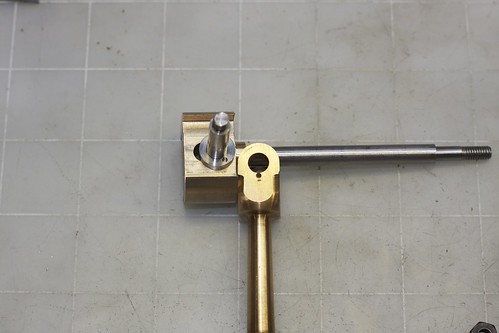
Guess what I found in the old fixings jar? Not one, but two 1/16" pins :D The newer fixings set that I got recently from Stuart for this engine didn't have any, so I'm glad these castings came with their own fixings set.

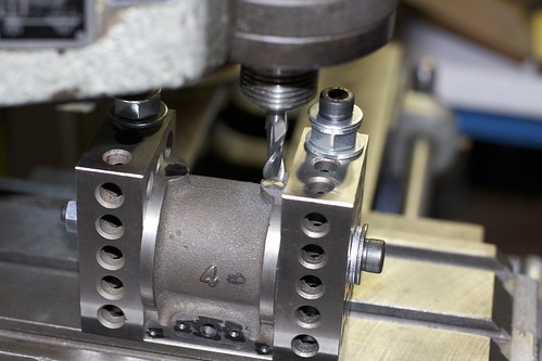
Made some good progress today. I'd been putting off milling the exhaust steam passage, but did so uneventfully, after carefully marking out the exhaust slot, and the exhaust hole on the side (with the same center height, of course). The two inlet holes were pretty wonky in the casting, and one is a bit wider than the other, so I tried to center the exhaust as best I could between them. Milling was starting with a 3/16" end mill, and finishing off with a 1/8", then the corners were filed square.


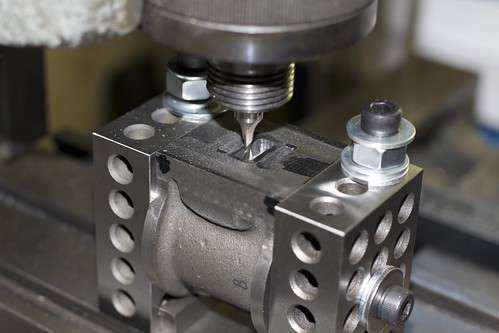
I probably should have drilled the 1/4" exhaust hole first so I could just mill down until I hit it, but did it the other way around, and it worked out OK.

Given that the steam ports aren't quite equally spaced, I wonder how smoothly the engine will reverse once complete. One possible solution would be to make a plate with accurate ports, mill a recess in the casting and silver solder it in, but I'm not keen on doing that unless I absolutely have to.

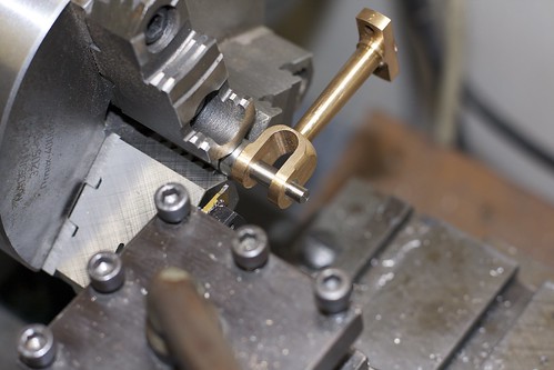
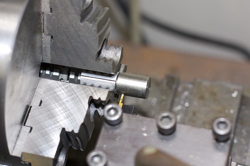
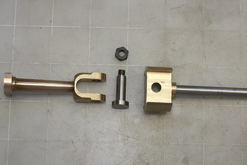
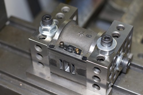
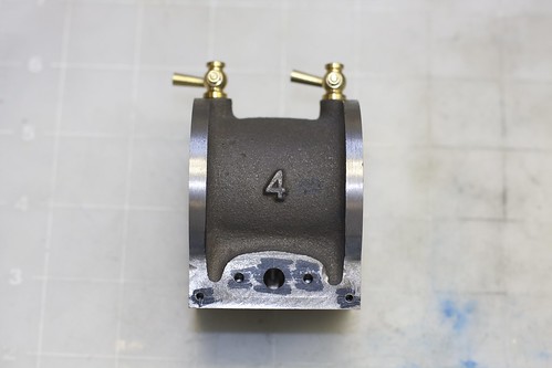
While I had the cylinder set up, I also drilled and tapped the holes for the exhaust manifold thing, and the lagging screws. Interestingly, the older models used a 5BA lagging screw (left side below), and the newer ones a 7BA (right side; the screws are in the exhaust manifold holes; I'm just trying to compare them visually here); I chose 7BA for now.


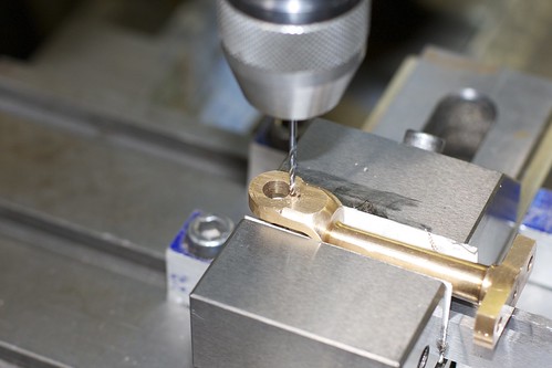
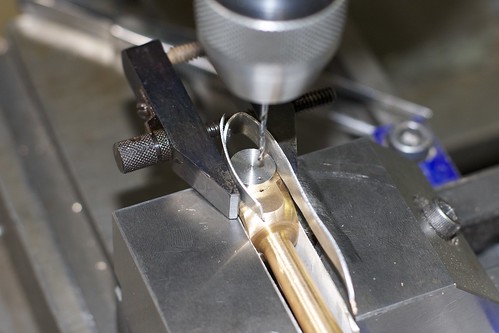
Now to drill for the drain cocks: spot-face, center drill, drill through and tap 3/16" 40TPI:


and the cylinder done except for the stud holes on each end:


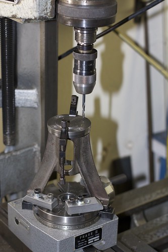
So, lots of stud holes to drill and tap: 6 on one end, and 4 on the other. I broke out my recently purchased 4" Phase II rotary table, centered the table under mill (via an MT2 arbor in the center hole), then centered the cylinder casting on the table. Boy, clamping things on this teeny table is tricky!


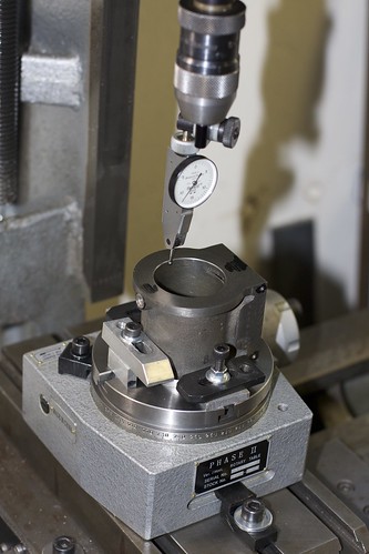
Once everything was aligned I cranked the carriage along by half the bolt hole diameter, and I'm ready to go!

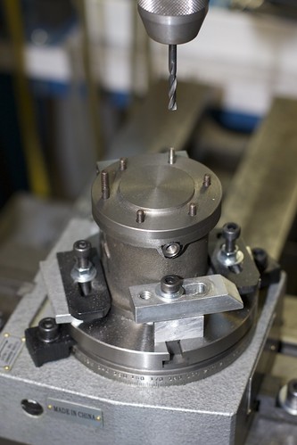
I drilled the top cover and the tapping holes at the same time (the cover was clamped for drilling), turning in 60° increments, then enlarged the holes in the cover to clearance size. Then I went back around the holes for tapping; I found that the rotary table was precise enough that I could accurately return to a hole position, which is nice. I started the taps in a chuck in the mill (turning by hand) to keep things straight.

6 holes tapped, and the moment of truth: does the cover fit?


(Spot the odd stud out!) Yay! In fact it fits in any orientation, so I guess I counted the rotations right :D

After that I did the 4 stud holes on the base on the cylinder. 4 holes this time, so line things up, rotate 45°, drill, crank 90°, drill, crank 90°etc. I jotted down the angles, and used those to double-check my handle-turning count.

Drilling the standard really pushed the limits both of clearance on my mill, and clamping on the rotab. I could just get the drill into the chuck, and don't look too closely at my clamping job here :D


I was relieved when all the drilling and tapping was complete without any broken-through holes and broken taps. Now for the fun part, assembly:


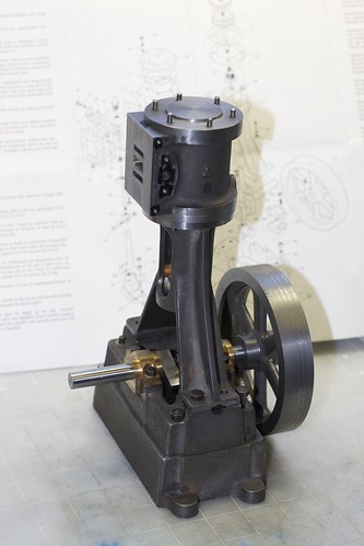
Wow, this thing is beginning to look like an engine 8)

Next up will be the piston rod gland. I'm a bit concerned about alignment there, having read another recent thread here about that. I have the right taps and dies (1/2" 26 TPI), but I wonder if single-point threading would be something to consider, having never done it before?

Thanks for following along,
Simon
 
Looking good Simon. I'm enjoying following your build. Your Emco seems to be a great option for someone with limited space

Cheers
Steve
 
Definitely looking the part Simon! I wouldn't get too wound up about packing glands. If you did the piston and rod square and true, the packing shouldn't be a problem. Does this engine have a screwed in packing, or bolted in packing?

Dave
 
Very nice work Simon.
It's been many years since I last built a Stuart but they sure are nice looking engines.
gbritnell
 
The port spacing shouldn't be an issue; just make sure that the valve travel is centered on them and not on the exhaust.
 
Very nice job indeed Simon, it is starting to look like an engine. Like Kvom said you should have no trouble with the port spacing.

Don
 
Dave, the packing gland is screwed in (with a hard-to-find 1/2" 26TPI BSB thread!). I actually made a quick tail post die holder for the die, and cut the thread already:


but I did that after reaming for the piston rod, and I'm wondering if it would have been better to tap the bottom cylinder cover, screw it down onto something to simulate packing, and then ream it in place. The risk is that it then only lines up at that particular orientation. I think it's OK for it to be a little oversize though.

Steve, I'm pretty happy with the Emco. The main limitation for milling is the tiny table (about 5" by 9", and deep rather than wide). Not even enough room for a decent 4" vice! I wish I'd kept the spare carriage that I had, so I could have ganged the two carriages together somehow.

Simon
 
Hey Simon

Well, if you want do get it absolutely true, you would have to first ream the bore; then use a turning mandrel to put the part on and then turn the threads between centres.

Else, it works quite good if you make a cone to the beginning so the die starts taking cuts with slow increasing depth..
(puh.. that was difficult to explain, didn't know how to describe that with the cone but I hope its clear what I mean...)
 
I understand what you mean by the "cone" on the end; take a small cut at an angle on the end (which means making the part over-sized to begin with, perhaps), matching that angle to the "starter" angle on the die. That assumes that the die is accurately ground, of course!

I guess I can use a similar trick to get the tap accurately centered in the cylinder cover casting (which the gland screws into).
 
Well, that with the cone itself would have been easy - what I wanted to say is that the cone angle should be very small, something like 10°.
And I don't know how you call that kind of cone - guess its not "small cone"

Cheers
 
Back
Top