Stuart No. 4 build

Home Model Engine Machinist Forum

Help Support Home Model Engine Machinist Forum:

This site may earn a commission from merchant affiliate links, including eBay, Amazon, and others.
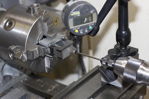
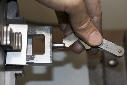
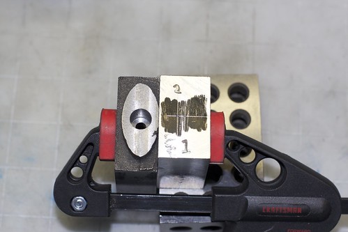
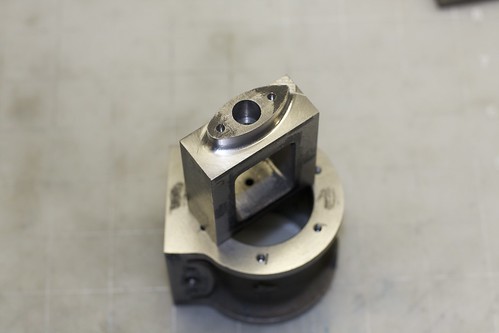
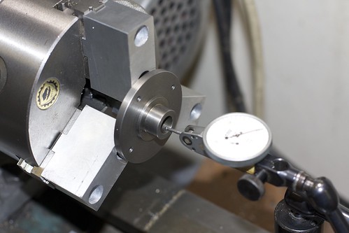
I plucked up the courage to thread the bottom cylinder cover for the piston rod gland today this evening. To hold the cover, I put the soft jaws onto the 3-jaw chuck, clamped the jaws down onto a bit of stuck, and cut a lip to fit the cylinder cover, then removed the stock and clamped down on the part. Here I'm checking with the dial indicator; runout was about a thou, which seemed reasonable.


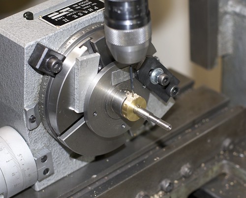
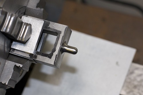
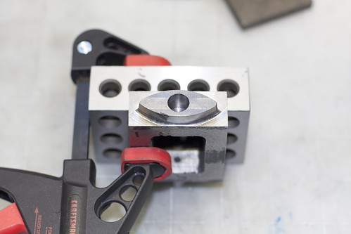
Then I put a small bevel on the bore so that the tap would start concentrically:


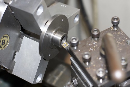
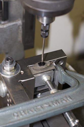
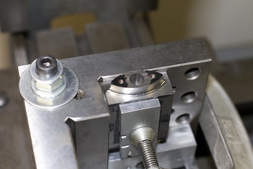
I was concerned about tap alignment, so fiddled around for a bit with shims under the leading edge of tailstock, and the drill in the chuck that I'd use to drill the part earlier, and got the drill sliding nicely into the hole. Then it was replaced with the tap, and tapping started under hand power, with the taper tap:


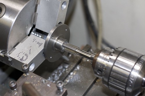
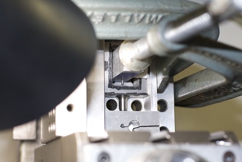
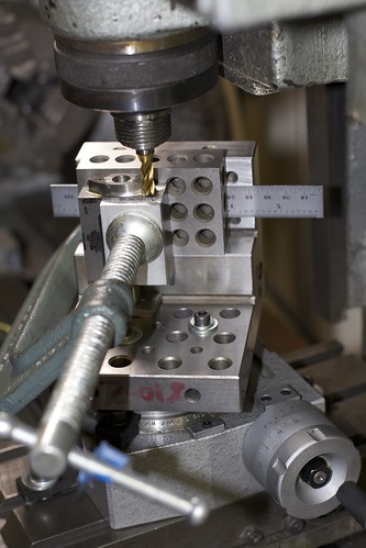
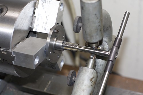
With this size tap it wasn't long before the tap was starting to rotate in the chuck (despite backing out the tap often to clean the chips), so more desperate measures were called for! The steady rest made a handy way to keep the tap straight so I could apply more force with the tap wrench:


I switched to the bottoming tap, then back to the taper tap, then back to the bottoming tap, and by the end was using two wrenches to turn the thing (but carefully!), and finally was done.

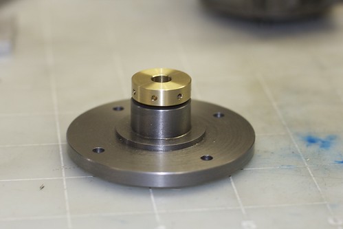
Hey, I can make it finger-tight, and the piston rod still slides through :D


The threads in the cast iron look terrible, but I'm not sure how much of that is my fault. These are HSS taps from Tracy Tools in Devon, UK, but they don't seem to cut as nicely as the HQS taps I have from Tap & Die.

Simon
 
Hey Simon,

A Karma from me for creative use of a steady rest! ;D

Looks like you got it beat! The gland bore doesn't need to be dead tight, a couple of thou clearance won't hurt it and the packing will take it up....but it seems you don't need to worry about that.

Nice Job!

:bow:

Dave
 
Yeah nice work with the steady, I sometimes support it with a tailstock centre and let the tap wrench come up against the cross slide but depends on whether the tap has a centre.

Soft Jaws has definitely got to be the best way for cylinder covers and the like, I've never had any but they look worth their weight in gold for such applications.

Top job :bow:

Nick
 
Nice job Simon.
Are they roller bearings in the steady rest?

Brock
 
It's looking good Simon. I'm excited to see this one run :)
 
Simon

I have been enjoying your build; the work on the cylinder is great.
I have given you a Karma point for the use of soft jaws.

Dave
 
Great job Simon, l like your soft jaws that is next on my list of acquisitions. Looking forward to seeing it complete. Keep up the good work.

Don
 
ShedBoy said:
Are they roller bearings in the steady rest?

Hi Brock

Yes, a previous owner did a hatchet job on the bronze fingers and fitted bearings; one of them isn't even square :-\ They leave marks on even steel parts, so I don't really like them. It would be easy to make new fingers; they are just a push fit.

Thanks for the comments all! Work is easing off a bit, so I have some more evening time to work on the engine now.

Simon
 
I left the piston rod gland set up in the rotary table last night, so couldn't resist drilling the 7 holes (capstan holes?) tonight.

I put an MT2 collet in the center hole of the rotary table, holding a spare piston rod (1/4"), so could use that to center the bottom cylinder cover with piston rod gland on the table, and allowed me to clamp the cylinder cover:


I did have to move the clamps around for the different holes though. I did 7 holes, 51° 26" apart, counting turns on the rotary table handle (hmm, could I have used the dividing plate? Not sure if it does 7's), with a 1/16" drill.

All done, lightly countersunk the holes by hand:


I did a quick assembly of the engine with the piston, and even without the piston rings, or any bolts holding stuff together, was getting some reasonable compression in the cylinder. This is quite exciting! Of course it probably means that the cast iron piston is a tad oversized; I think I want about 0.002" of clearance for a cast iron piston in a cast iron cylinder, with cast iron rings?

I think I'll work on the valve chest and value parts next. The eccentric strap is probably the most tricky part left; I'm going to make the simple value fittings first as practice, get it all working, and then do the reversing parts later.
 
Simon

Still following your progress and enjoying your setup photos and explanations. Keep it up.

Vince
 
Simon,

I note that you've been focused on building the engine and not sidetracked by the running-in issue that you raised. Add my applause also for the use of a steady rest when tapping the gland boss. It is a trick that I shall use in future. It demonstates a methodical approach to the task. Your engine will be a fine example when finished. Good luck with drilling the steam passages (or did I miss that?).

Brian
 
".......I did have to move the clamps around for the different holes though. I did 7 holes, 51° 26" apart, counting turns on the rotary table handle (hmm, could I have used the dividing plate? Not sure if it does 7's), with a 1/16" drill......"


YUP you could use an index plate....if you have them for that table...
Do you know what the ratio is of the table and what hole counts you have with the plates?

Dave

 
Hi Simon,
When you have difficulties tapping, provided your tap isn't as blunt as a boxing glove, try opening the hole slightly. It will reduce the %engagement slightly but you will be surprized what you can get away with. You don't have to follow slavishly the books on tapping sizes.
Ned
 
Runner said:
I note that you've been focused on building the engine and not sidetracked by the running-in issue that you raised.

Thanks Brian! I'm pretty sure all the tightness is in the connecting rod on the journal, and there because of the radius on the journal ends interfering with the sides of the split bearing. I just need to work on that some more.

Runner said:
Your engine will be a fine example when finished. Good luck with drilling the steam passages (or did I miss that?).

The steam passages were cast as part of the cylinder casting, so the exhaust slot was the only one that needed drilling out. I can blow through the steam passages, so I assume they don't need clearing out.

steamer said:
YUP you could use an index plate....if you have them for that table...
Do you know what the ratio is of the table and what hole counts you have with the plates?

I just looked it up, and I could have used the dividing plate; the one for this little 4" table is somewhat limited, but does 7s (it has a 28-hole circle). Darn, missed a chance to use a tool for the first time!

Thanks for the continued interest,
Simon
 
".....I just looked it up, and I could have used the dividing plate; the one for this little 4" table is somewhat limited, but does 7s (it has a 28-hole circle). Darn, missed a chance to use a tool for the first time!..."


Yea.....but you won't next time... ;D

Keep at it man your doin fine!

Dave


Simon,

revisiting your picture using the steady rest I note that you use a nut and bolt to stop the gland from turning in the soft jaws. Little things like that are indicative of your planning skill. Think twice do once!

Brian.
 
Simon,

I have a rotary table like yours and was considering some MT2 collet's for it. Where did you get your collet's, are they short and have a draw bar?

Ed
 
RCGUY said:
Simon,

I have a rotary table like yours and was considering some MT2 collet's for it. Where did you get your collet's, are they short and have a draw bar?

Hi Ed

The collets came with my lathe; the previous owner had assembled a set, and a couple of them are shorter (which is very annoying, forcing you to swap draw bars!). I see MT2 collets on eBay, which are probably equivalent quality to what I have. The longer ones are a bit too long for this rotary table; I think they stick out of the back slightly.

Brian: I added that nut and bolt after the part started to rotate :D

Simon
 
The things we make teach us a lot don't they!
:big:

:bow:
Dave
 
I worked on the valve chest today, which seemed to be a bit slow going.

First step after marking up: square up the inside a bit. No critical dimensions here, just need room for the valve to move.


This kit is old enough that the valve guide is cast into the valve chest; the newer models have a brass fitting that you machine separately, then screw in. I suppose that avoids having to drill deep through the valve chest and adds some brass bling, but I think I prefer the old way.

Anyhoo, the valve chest was chucked up in the 4-jaw with some backing, and a wiggler and indicator used to center on the punch mark at the end of the valve guide:


I started with an HSS ground tool bit because of the interrupted cut, and to take the crust off the casting. Towards the end I switched to a carbide insert tool, which does risk getting chipped because of the interrupted cut, but actually performed fine. After a bit of turning we're close. Both radii were done "freehand" and cleaned up with files. Here I'm using a radius gauge to check the shaping on the end:


and in this photo the neck radius still needs some cleanup. With a bit more work it's almost done:


but I still need to get rid of some tool marks around the base.

Now it's time to drill and ream for the valve rod. The angle plate on its side serves as a useful way to hold the casting square (the sides have already been machined), and we locate on the punch mark:


The top end is drilled then reamed 3/16", and the bottom end has a 1/8" hole reamed into the valve guide. Luckily, for the lower hole, I had an extra long drill that I'd picked up at a yard sale or flea market a while back, but of course it wandered all over the place when trying to enter the bottom of the casting.

My solution was to clamp a block of Al inside the valve check, switch back to the stubby drill then drill through that to form a guide for the longer drill.


This worked nicely; with the block still clamped, it acted as a guide for the longer drill which no longer wandered, and I was able to complete the lower hole, then ream 1/8".

The upper hole was also opened up to 3/8" using a small boring tool; the valve rod gland fits into this.

I now pondered long and hard about how to do the profiling on the lower side of the valve chest. I guesstimated from the plans that the curves have a radius of 1", then blend into a radius around the bolt holes. To machine the curves, my options were the rotary table (setup too hard on my tiny table), the faceplate (easier setup, but hard to control the radius from the center), and the 4-jaw. After hatching a cunning plan to get the right offsets, the 4-jaw won.

I used a scrap block of Al as a simple fixture, and computed and marked out two punch marks:


When the fixture is located in the 4-jaw with the appropriate punch mark centered, I know that if the valve chest is clamped against the fixture the right way around, I'll hit that 1" radius for that side of the valve chest.

Here's the 4-jaw setup, with the fixture clamped in the middle, and the casting held by just one jaw.


Not an ideal way to hold something in the 4-jaw, but the setup was pretty rigid so I wasn't too worried. I've already centered the fixture on punch mark no. 1, then I had to fiddle around a bit to get the casting lined up (using a square to align the chuck, and a height gauge locating on a drill bit which was a tight fit into the reamed hole). I've mostly finished one side in this photo.

After doing both sides it looks like an eye :D


I didn't quite get things lined up, so there's a bit of a step where the machining of the two sides comes together; I'll have to clean that up by filing later.

Back onto the mill, using the angle plate setup again, to locate, drill and tap the holes for the gland screws:


Now another crazy setup ;D I wanted to round off the corners of the "eye" shape on the rotary table. The only way I could figure out how to hold it was on the angle plate:


There's a little rotary table under there somewhere! Usual rotab drill: locate the rotary table under the mill and clamp it down. Set up the part on the table, also centered (I used a drill bit dropping into one of those tapped holes for location). Now use the carriage to adjust the radius being cut.

I don't have any ball-end mills of the right radius, so I milled a few steps, then cleaned up with a file. Here we are, one side done:


This part is on the underside of the valve chest, so I don't have to get too crazy with finishing, and it might even be painted. I can never decide whether to paint valve chests!

Tomorrow I hope to finish the profiling here, mill the chest down to thickness, do the valve chest cover, and drill and tap for the studs that hold the valve chest to the cylinder.
 

Latest posts

Back
Top