Stuart No. 4 build

Home Model Engine Machinist Forum

Help Support Home Model Engine Machinist Forum:

This site may earn a commission from merchant affiliate links, including eBay, Amazon, and others.
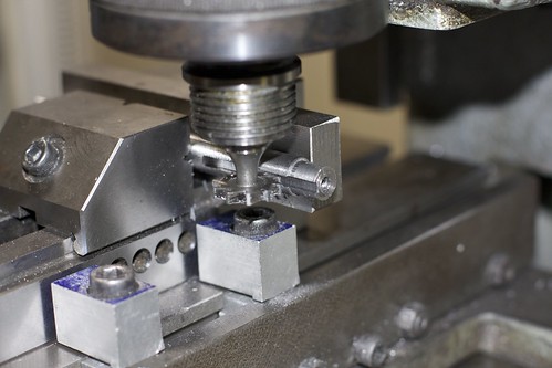
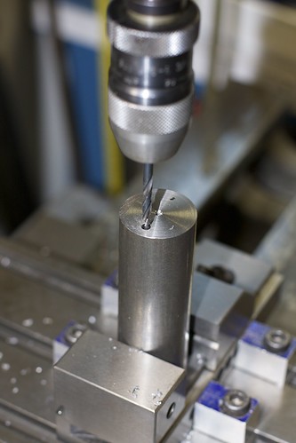
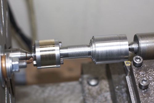
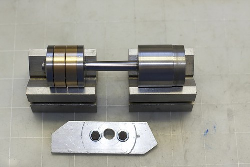
I finally got some time to finish off the main bearings. First job was to clamp the soleplate to an angle plate, taking care to get it aligned, and ensure that the bearings were screwed in tight.

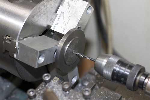
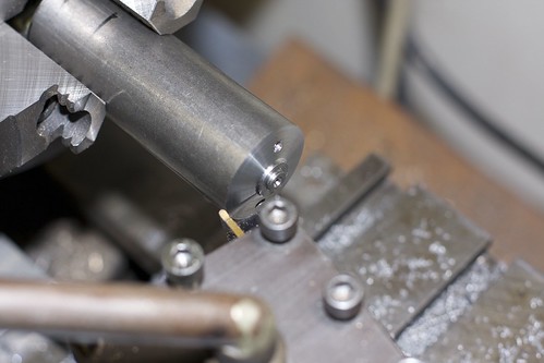
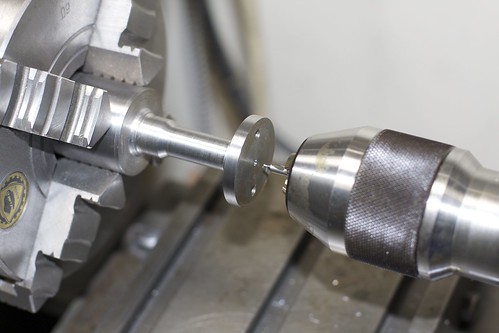
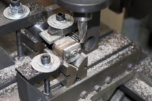
Then onto the mill, lined up and drilled in increments:


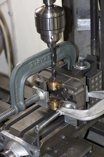
I stoned the drills to reduce the tendency to grab in gunmetal, which mostly worked. I was careful to drill slowly, and keep pressure on the quill feed to avoid the drill getting pulled in too fast.

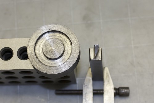
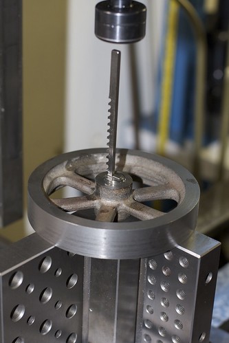
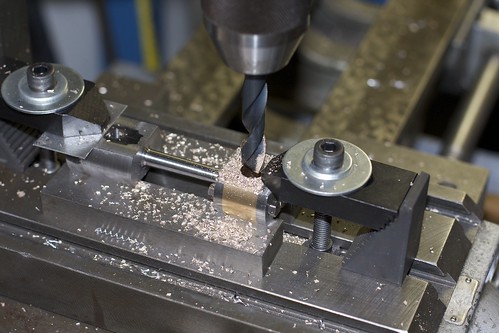
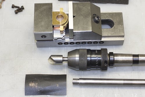
After drilling to 1/64" undersize, I switch to the reamer.


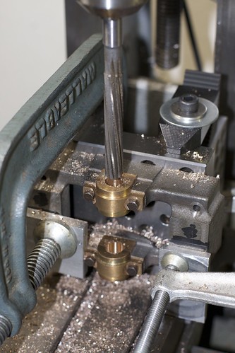
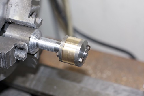
This is a right-hand rotation, left-hand spiral reamer. It's a hand reamer, which means it has a taper. [Please note warning in later reply about using hand reamers in the mill.] Because of that I can't go through both bearings from the same side, so I went as deep as I could from one side, flipped over the entire setup (one of the G-clamps had to be moved, but the other kept the soleplate aligned), and relocated on the hole:


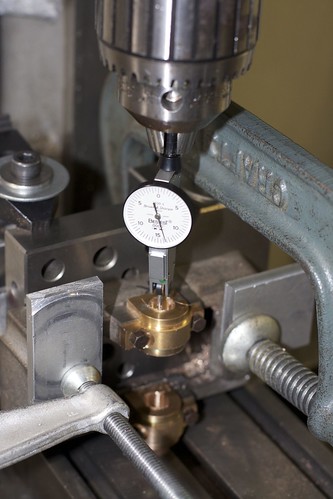
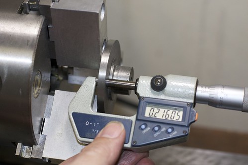
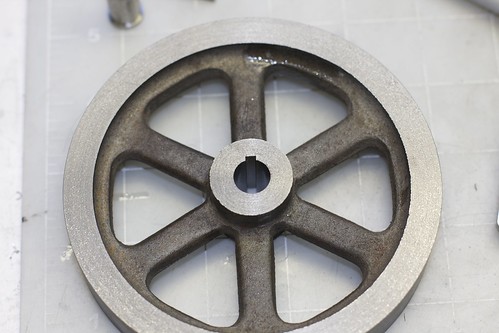
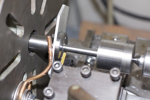
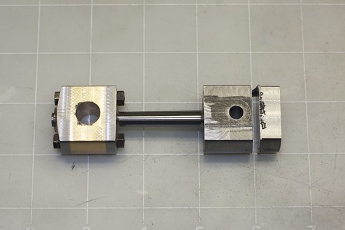
I then reamed from that side, and cleaned up the edges with a light touch of the countersink. Now for the acid test: did I mess up the alignment?


Phew, things seem to line up!

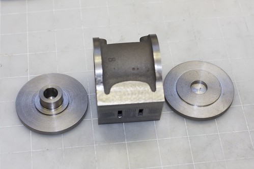
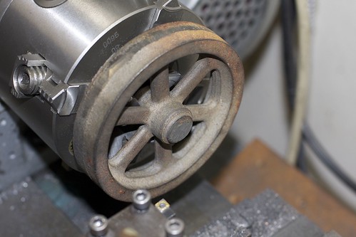
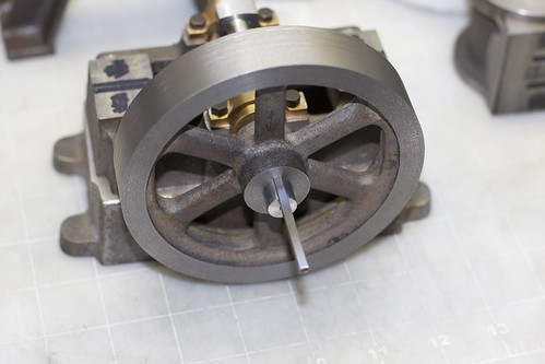
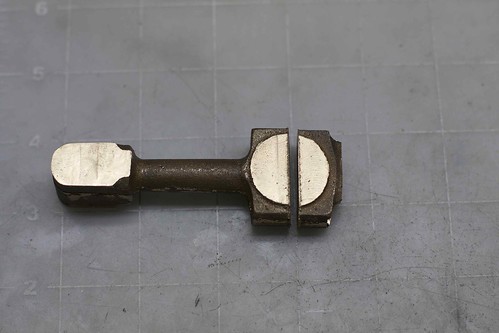
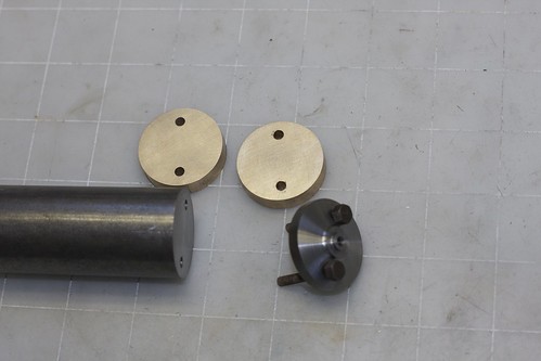
Now the crankshaft still doesn't fit because of the radii:


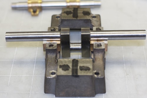
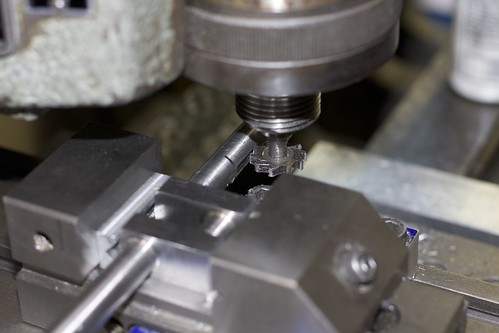
Oddly the plans show zero clearance between the bearings and the crank throws, but I'd reduced the bearings a little to leave some room, and the radii keep the crankshaft from moving side-to-side. However, the bearings needed some relief to fit the radii, which I did by hand with a countersink and some wet & dry:


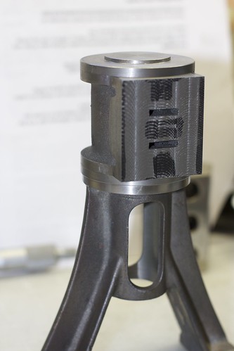
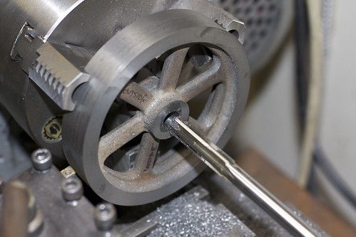
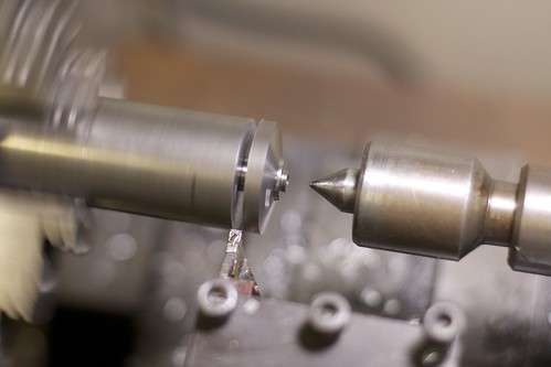
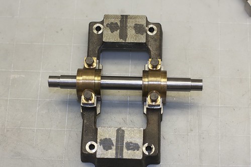
Then I did some initial settling in with some Brasso as abrasive, turning the crank by hand:


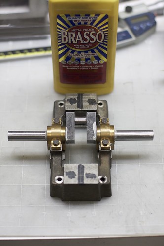
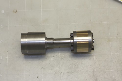
The final fit seems pretty good.
 
Looking good Simon :)
 
Great job Simon I have been waiting for you to complete the bearings and crank. You mounted it the way I would have done it. I would of used a chucking reamer and went straight through. Is this the correct way to do it?

Don
 
Hi Don

I don't know that there's any "right" way, but we do what works (and sometimes not ;) )

I would have used a chucking reamer if I'd had one with spiral flutes. I avoided a straight-flute reamer because the bearings are in two parts, so the flutes might grab on the join. Also, the chucking reamer would be longer, and I'm not sure I have enough head room on my mill for that.

The other reason to do it the way I did is that going through both holes with a long reamer might end up leaving the upper hole oversize, if the reamer isn't perfectly straight in the chuck. Floating reamer holders exist to solve this problem, but I don't have one.

When I bought the hand reamer I didn't realize that it would have a taper, but now I know!

Simon
 
Thanks Simon for clearing that up for me. It helps to get input on how and why.

Don
 
Made some good progress today. I'd roughed out the bottom cylinder cover earlier, and today almost finished it. I made use of the soft jaws I made for my newly acquired 3-jaw. First I clamped the jaws down onto a bit of bronze of a diameter which put the jaws roughly in the right location, then faced the jaws, and bored a step which will hold the part. I could then clamp down on the part, and have it accurately centered.


In this setup I did the upper faces, with a 1/16" step which gives a close fit to the cylinder. I also took the outside diameter down to size. Since alignment of this face with the center hole is critical, I drilled and reamed the center hole 1/4" in this setup. I'm deviating from the older plans, which call for a 9/32" piston rod and using 1/4", since I have the 1/4" tooling already. Stuart moved to a 1/4" rod on the newer models, presumably because the material and tooling is more readily available.

Then I removed the part from the chuck, and re-bored the chuck jaws to fit the step in the part I just made, then flipped the part around and put it back in the chuck. I then took a light facing cut, and checked that the flange had a similar thickness in three spots:


That tells me that the part is aligned in the chuck. I also checked for concentricity with a dial indicator on the rim, which was within a thou.

The steps on the lower side of the cylinder covers where then turned to size, fitting to the standard. The boss for the packing gland was drilled for threading, but my BSB taps and dies are lost somewhere between Devon and California, so I wasn't able to cut the threads today :(

Here's the cylinder with both covers:


and everything in place:


Here you can see my earlier boo-boo of turning the top flange of the standard to the wrong size. I'm not quite sure if I want to do anything to rectify that.

While I had the lathe covered in cast iron dust, I roughed out the piston casting. The piston has a groove in one face, and a recess in the other, which gave me an excuse to work on my tool grinding skills ::)


Here's my attempt at a cutter for these kinds of face grooves. It worked OK, but I got a fair amount of chatter because of large cutting area, since it's radiused.

I'll finish off the piston when I've made the piston rod. Sadly all my 1/4" precision-ground stainless is curved, so I need to get some better material.
 
Simon,

I have only just started to follow this post, so I read and then re-read it.

Your doing a wonderful job seeing as you haven't been doing it long.

Your posts are like an old pro, lots of very good info in there for followers to glean.


Very well done indeed, and keep it up.

John
 
Hello Simon,

If you have a straight shank chucking reamer that is too long for your set-up, it is usually possible to easily shorten it by chucking on the straight shank and parting it off in the lathe. Check the relative hardness with a file first to make sure it is not full hardness and keep the parting cut close to the chuck jaws. The chucking reamer's shank is not as hard as the cutting edges and a HSS tool will usually do the job. The hardness of the shanks are usually tempered back to increase the toughness, just like a drill bit. I do this quite often as my Clausing milling machine is also challenged as far as the distance between the spindle and table for some set-ups. After parting off, you can open your chuck jaws, place the cutting edges behind them and face and chamfer the end of the shank to make a proper job of it (if parting left a 'pip' that you care to remove).

A right-hand cut (normal CW rotation), left-hand spiral chucking reamer would have been a good choice for line reaming your main bearing journals. You really should never use a hand reamer in a powered spindle because they are not designed for it (rake, and relief angles) and will dull very quickly. They don't have the support behind the cutting edges that a chucking or machine reamer has. Any reamer with a square-drive on the shank is a hand reamer and would only be driven with a tap handle. When using a hand reamer, you would typically only leave a few thou for the reamer to remove depending on the diameter, as they are a finishing tool.

You had the right idea with the LH spiral and I am glad that it worked out for you. The RH rotation, LH spiral is much less aggressive than a RH spiral because the LH spiral has a negative axial rake, which 'pushes back' against the thrust of your spindle and will give an excellent finish. A RH spiral would have a positive axial rake and would tend to pull the spindle along which, if you have a worn machine, can induce chatter and leave a poor finish. BTW, to determine the 'hand of the spiral', look along the axis of the tool and if it twists to the left it is LH cut or spiral and vice versa. Obviously, a straight fluted reamer has a neutral rake angle.

A trick that I learned from a journeyman I worked with long ago with regards to getting the reamer to follow the axis of the hole when you don't have a full floating reamer holder is to just chuck at the very top of the shank with the minimum amount driven by the drill chuck jaws. This was often done in the drill press where you could use the long length of the chucking reamer's shank to your advantage and where you weren't normally concerned with running out of space between the spindle and the work. It can also be useful in a vertical mill. However, like all short-cuts and 'tricks of the trade', it raises some concerns. First, you have to have enough of the shank in the chuck to drive the reamer and second, it isn't the best thing for the drill chuck. We used to do this to overcome the runout of a worn drill chuck in the drill presses. (It was no wonder that this portion of the chuck jaws is always worn in a commercial shop.) If you fully chucked on the shank, the reamer would have an unacceptable TIR and an oversize hole would result. Use this cautiously. It can get your tail out of a crack. Would I do this in my new Albrecht chuck...NO, Never!

Great job so far. I enjoy following your progress. And you are absolutely correct, that we all use the means that we have available to us. Nice work with your soft jaws as well, that was a perfect application for them.

Kind regards,
Mike
 
Thanks Mike for your input this helps clear things up for me. I understand this a lot better, not that your input wasn't enough Simon just another view helps.
You have made good progress, I do like the way you do and explain things as you progress. As a newbie I need all the help I can get.

Don
 
Thanks Mike, that was a great summary of reamer issues! I didn't realize that hand reamers were so different. I will go back and edit that post to clarify that it's a RH rotation, LH spiral reamer.

It seems like us folks with limited headroom are a bit stuck when it comes to using larger reamers on large parts. All methods to improve alignment seem to require more headroom. As you say, shortening the reamer is possible, but I assume that reduces flex, and might result in an oversize hole.

Another option of course is to ream on the lathe, but that requires some tricky setup to get the part at the right height.

Simon
 
I regularly cut chucking reamers shorter to fit the mini-mill. With an abrasive cut-off wheel...
 
Flywheel time! While the lathe was covered in cast iron dust, I thought I might as well tackle the flywheel.

I started out in the 4-jaw, gabbing the hub and adjusting until things were running as true as I could get them.


The outer edge of the casting was pretty messy, and dulled an HSS tool pretty quickly, so once I got the skin off, I switched to my trusty insert tool (from http://www.latheinserts.com/).

The (older) plans the hub flush with the rim on one side, and 3/16" proud of the rim on the other, so that's what I did. Stupidly I left the hub proud on the more wobbly side :( I'll probably skim the hub, and I need to do the inner edges of the rim to make things pretty. I left some material on for a later finish pass, once it's mounted on a shaft.

The hub was drilled and reamed 7/16", which was uneventful.


I pondered for a while how to attach the flywheel to the shaft. The older plans call for a keyway, and the newer ones a grubscrew. I hate grubscrews, so it was either a keyway or something like a taper hub (discussed here http://www.homemodelenginemachinist.com/index.php?topic=11471.0). A taper hub wouldn't look very authentic on a Stuart model, unless fancied up somehow, so I went with the keyway.

First up was a practice run with the woodruff cutter on some spare 7/16" drill rod, which worked pretty well. I'm doing conventional cutting here (part moves right to left).


With that experience, I made a collared broach bushing from some easy-machining stainless. It was a simple case of turning down a section of 1/2" rod to 7/16", then cutting the slot as in the photo above (noting that the back of the broach is 4 thou over the nominal size). I did the math to compute how deep the channel needed to be to give me the correct final depth of keyway on the flywheel, and figured that I only need to do two passes with the broach, first without the shim, and then with the shim. Finally it was parting off leaving a collar, and cleaned up with a file.


Now for the broaching step. There's no need to clamp things down, since the broach is held in place by the bushing. Care needs to be taken to align the bushing to start off with (the slot aligns with one of the flywheel spokes), and mine was a light push fit so it stayed in place. I used an angle plate with a large hole in it to give clearance for the broach, and used the mill quill feed with an old saw arbor in a collet to push down on the broach. It took some amount of force, but I didn't feel that it was enough to harm the mill.


One pass without the shim, and a second pass with the shim gave a slot of about the right depth.


Phew! I was worried about the broaching, but it actually turned out well. I'm tempted to go back and apply the same technique to my Stuart Beam.
 
Hi Simon, glad to see you running with it again. Nice photos, I haven't broached any wheels yet and I do have a set. I want to give it a try since I have seen you do it. You are coming along really good, keep up the progress. Is that a five or six inch wheel?

Don
 
Hi Don

Nominal diameter of the flywheel is 4.5".

I built up the courage to cut the keyway in the crank:


and it went smoothly. I had enough room to fit the flywheel and check the depth of the cut, and adjust accordingly.

A test fit:


The flywheel has a bit of play, but I'll be able to fix that when I make the actual key.
 
That came out real nice Simon. More great photos. I am getting anxious to see the finally.

Don
 
Simon

Thanks for your description of the broaching operation. It was extremely informative. I need to do some broaching also when I manage to get my hands on a 2mm broach and your explanation answered some of my questions I had in my mind.

What size is the keyway you cut? I need to make the keyway in brass and also drill rod. In the brass it should not be a problem if I use the mill quill feed just like you did, but I am still unsure if the quill feed is strong enough to broach the drill rod. I do not want to damage the mill.

Vince
 
Hi Vince

This was a 1/8" keyway.

One issue with broaching is that you really don't get to adjust the depth of cut; that's "built-in" to the taper on the broach teeth. I'm not sure if they sell broaches with different cut rates.

If you're broaching brass, the brass might actually be trickier than cast iron, because the teeth might dig in. Someone with more experience than me in broaching brass should chime in here, but I wonder if "stoning" the teeth to take off the rake would make it easier?

If cutting a keyway in drill rod (I assume along the length of the rod?), you'd use a woodruff cutter as I did, or a small end mill. My test cut was on drill rod, and it was fine. I went in about 15 thou on each pass, with lubricant.
 
Simon

Thanks for the info. What I meant by a keyway in drill rod was that I also need to broach a keyway in drill rod. Obviously when I come to that stage I will be making test cuts in both brass and drill rod.

Vince
 
Work on this project ground to a halt for a bit, partially because I was annoyed at myself after http://www.homemodelenginemachinist.com/index.php?topic=18463.msg190483, and also because of interior decorating and lots garden work in the spring. But I've managed a couple of weekends in the garage, and the saga of the connecting rod continues!

Here's where we left off when I used a blunt saw, and insufficient clamping to cut the top off the gunmetal conrod casting:


The cut is crooked in both axes. I tried to silver-solder the parts back together, but that was a disaster as well. Not having done any silver soldering before, I didn't practice enough beforehand, and the solder penetration was terrible. So, plan B:


That's a hunk of 12L14 and two bronze rounds. The plan was to build up a conrod with a split bronze bearing from this lot. So, here we go! I have to hold the split bearing and steel together with bolts, so I need some bolt-holes. The end of the steel rod was cleaned up, and holes drilled accurately either side of center:


Then I formed what would become the cap on the big-end of the conrod:


and parted it off:


That insert parting tool actually does a reasonable job on my Emco Maximat "Standard".

The bronze disks also get reduced to the right thickness, and drilled:


Now I can hog out some material on the main part of the conrod, which reveals the ends of the holes drilled earlier, and allows for the bronze disks to be bolted together.


Now I can turn between centers. At this point I'm reducing the overall diameter to what will be the largest width of the big end.


I'm turning both ends to the same diameter at this point, so that I can easily clamp it down to mill some flats later. After a bit of turning we end up with this:


Still a lot of metal to remove!

At this point I realize that the bolt heads get in the way of finishing the taper on the center section, so I take it apart, and locate and center drill at a point which will be hidden under the bearing on the finished part:


Now I can turn this section alone between centers, and form the taper. Hmm, does everything seem right here? Whatever, soldier on!


We stop for a second to admire the work so far:


Now to mill some flats. The consistent diameter allows me to clamp it in some V-blocks:


Clamping down on the thinner center section is iffy since it could pull the rod out of true, but I didn't tighten that clamp down much. By shifting clamps around I could reduce both ends to the same thickness; it was then flipped over, clamped to the table, and the other side milled down. I took it down to the distance across the "Y" of the little end (11/16"). Now we can drill and ream both ends in the same setup, ensuring that they are parallel:


Of course the hole at the big end has its center on the seam between the two bronze pieces.

Next I take off some excess material on the little end, which was a successful slitting saw operation (yay!):


Feeling pleased at the progress, I put it to bed for the night.

Next day, I pick it up, wondering how best to set it up to saw some more off the little end. Then it hits me. The taper goes in the wrong direction! Headdesk. :mad: Time to leave the garage and find something else to do for the rest of the day!
 

Latest posts

Back
Top