Stuart No. 4 build

Home Model Engine Machinist Forum

Help Support Home Model Engine Machinist Forum:

This site may earn a commission from merchant affiliate links, including eBay, Amazon, and others.
Hi Simon,
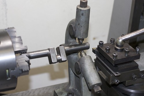
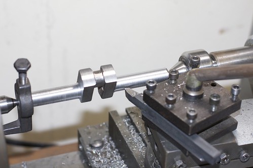
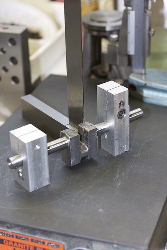
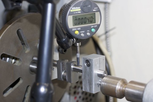
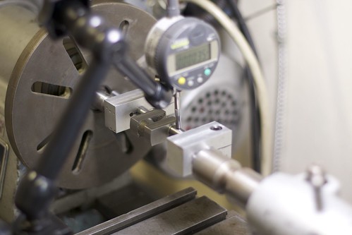
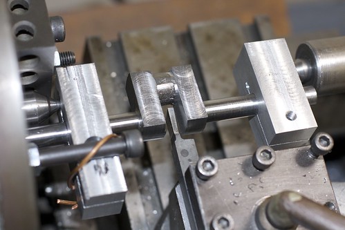
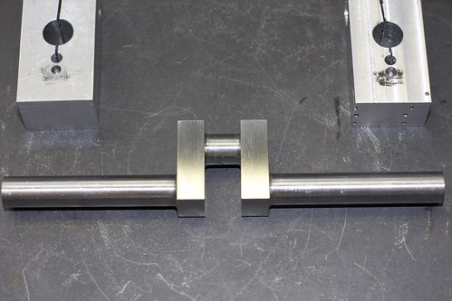
Hope you won't mind if I make a comment on your expanding mandrel set but it might, should you go the same way again, prevent a possible hitch. Using aluminium on aluminium as the expanding taper could cause galling and a total pick up of material which if it does could prove the devils hind teeth to release leaving the mandrel well and truly stuck.

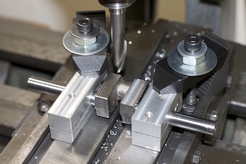
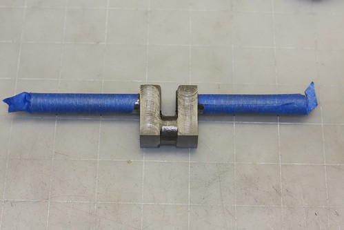
I don't want to teach granny as you are doing a very able job but mandrels made from steel using an ordinary caphead cut at a taper to match a centre drill are very easilly and extremely quick to make. Should you be interested the method I have used for many years at home and at work are shown about halfway down this set of images
https://picasaweb.google.com/Tug423/RW29DieselEngine#5455290402397533234. These have been made using the same principle from 4mm dia to well over 40 using varying capheads 8BA to 8-10 mm. They grip with amazing power with remarkably little torque on the screw.

Hope you won't think I'm interfering but ali will, and does, pick up so easily :eek:

Regards - Ramon
 
Thanks for the comments, Ramon! I'm still very much a newbie, so all advice welcome!

I did oil the plug to avoid it sticking, and didn't really have problems, but your point is well taken.

The trick of cutting a cap head with a taper to match a center drill is neat! And I can see from your mandrel how you reduced the material towards the center to allow the necessary flex. I was thinking in reverse, and thinning the walls to allow flex (probably because I've been using expanding laps and following that line of thinking).
 
I use a pipe tap in the end of the mandrel, the corresponding pipe plug expands the mandrel. The hex socket head plugs leave the face of the mandrel flush.
Greg
 
Ah but guys, how do you get a pipe nipple to fit a 4mm mandrel ??? ;D

Anything tapered will do it of course but tapering a caphead was how I was first shown it and it's stuck ever since.

Simon, for a newbie you are doing a cracking job - may I say, you definitely have a good way of going about things too.
Re the oiling on the taper - yes it will help, or a dab of grease but with an ali mandrel better to have dissimilar metals in the first place just to be on the safe side.
Also as it's not that clear on the link cutting the slots in is done before finish turning to size ie rough it out, remove to cut then back in the lathe putting the screw in and just nipping it up before finish turning. After the initial use they can be reset again but I find it easier to use them for 'the next size down' re-turning them to ensure total accuracy ...theres a lot of mandrels under the bench ;)

Ramon
 
OK, after mucking about with chucks and soft jaws, I got back to the Stuart this weekend. I'm waiting for some tooling to arrive to finish the cylinder covers, so I started on the crankshaft. I've been somewhat dreading this, but it's turned out fine so far.

The first job is to set it up with the steady rest, in order to face and center-drill each end. I used a bit of bar stock of a similar diameter to get the steady rest fingers in roughly the right spot. Just the tip of the casting is gripped in the 3-jaw, since we can't assume that the shafts of the casting are aligned (and they are not!).


I'd cleaned up the spot under the steady rest with a file, but this thing was still wobbling all over the place. However, I managed to face and center drill:


even though the drill was flexing. With one end done, I flipped it around and did the other. From now on, it will be turned between centers.

I used a sharp-tipped HSS tool to take off the bulk of the material. I only worked right-to-left, so flipped it around for the other side.


I figured this sharp tool would place less stress on the casting, but the finish was lousy. I also used it to rough out the throw sides and ends. Cleanup was done with some indexable tooling, including a radius insert on a Nikcole mini-system tool, which gave a great finish. I used wet-and-dry backed by a parallel to get to final diameter, and was able achieve a nice finish.

Next up was making a couple of fixtures for the offset turning. One is longer than the other to act as a lathe dog. I actually made up these fixtures after finishing one end of the crankshaft, so I could use the longer fixture as a lathe dog to avoid marring my just-finished shaft.


Making these gave me a chance to try the 7/16" reamer that I'll use for the main bearings. Good thing too; it's a spiral hand reamer, and I discovered that it has a significant taper over about half of its length. I won't be able to go straight through both bearings with it, but I think it should be fine to finish them off by hand.

You can see my awful wandering hacksawing (I had to use a junior hacksaw when starting from the reamed hole). Holes were drilled, part clearance-drilled and part tapped M6 for the socket screws to clamp the fixtures.

What you can't see is that I messed up when center-drilling the points that will be used to turn between centers. I forgot that these fixtures needed to be mirror-imaged. I'm not sure yet whether to center-drill the other side, or shim the few thou of offset when I flip one of the fixtures over as I clamp them onto the crankshaft. It's pretty critical that everything is lined up when turning the journal.

I also hope that the Al isn't too soft for these fixtures; I'm using a live center in the tailstock, but there's a chance the cutting forces will cause things to loosen up. I'll have to keep an eye on the tailstock pressure.

Before turning the journal, I think I'll mill the throws to thickness (using the fixtures to keep things square). That's for tomorrow!
 
Hi Simon,

Great Progress!

Was the crank rough turned when you mounted it in the steady?

It sounds like you have a hand reamer. They have a bit of taper to them. If you can get a chucking reamer, only the first diameter of length or so is tapered.

No worries about the hack saw.....the fixture will work just fine.

Keep going!

:)

Dave
 
Hi Simon,
A little bit of information on your turning fixtures. I can't tell from the photo but both fixtures should be the same width and have the holes drilled and reamed exactly in the center. The reason for this is when you clamp the crank into the fixtures plates this is the only way you have to align the axis perfectly.
gbritnell
 
steamer:

The crank was not rough turned when I mounted it in the steady, but I had filed off the worst of the lumps. I'm not sure how I could have held it for rough turning, without a rotating chuck in the tailstock (which I don't have). Maybe I could have just turned a short section close to the chuck end?

gbritnell:

I did mill the fixtures as a pair, so their widths match, and the holes are aligned, but I forgot to mirror-image them. The holes aren't exactly on the centerline, so if I flip one over, the crankshaft is slightly canted. I think I can shim up the low one though, using a height gauge to ensure that the crankshaft is horizontal when I clamp them down.

Simon
 
Hi Simon,

Well, you could make a bushing with an OD larger than the throw, and split in two with a concentric center hole of the nominal size of the rough journal. I would use this to put the center in. Then turn on centers....probably more trouble than it's worth

OR...and probably what I would do cause I'm lazy

If there's enough stock to deal with the out of roundness of the journal, you could just grab one end in a 4 jaw and set the other end to run as true as possible, and then center drill. Then flip and repeat for the other end....then turn on centers.

If it gets the job done, it's the right way, so what you did was fine!

The only thing I worry about with a steady in this situation, is the rough OD will load up the steady and maybe do some damage to the steady....like when people lock down the open steady before they back off on the top jaw of the steady which usually breaks the hinge......

Dave
 
Hello Simon,

Could you clamp on a pin with the un-center drilled faces of your fixture out, trim the sides again to make the crank pin hole central, then using a stop on the side of your milling vise, center drill the fixture for the offset. If the pin is protruding slightly from the top, you could measure the centrality with a depth mike. Drop the pin below the surface when center drilling, then flip the fixture to center drill for the throw. Make sure the the end that you use for the stop is square to your centered sides.

You can't use an as-cast surface, especially a sand cast one or a rough forging, if that is what the crank blank is, as a bearing surface in a steady rest as is isn't round. You should have enough of a central hole in one of your new chucks to insert one end as far as your spindle taper will allow and just true-up the other end. A four-jaw chuck would be best for this initial turning as you can average out the material. This would allow facing and center drilling with light cuts or you could turn the area that would provide a cylindrical surface for the bearing of your steady rest.

You are doing a great job on your projects as well as documenting your efforts. Keep at it, your logical approach to your problems and your progress is inspirational to new machinists who are getting started in the hobby. I know I am not the only one who looks forward to your posts.

Hope this helps.

Kind regards,
Mike
 
Hi Simon still on the side line here. Getting more info from the replies to you, good stuff. I quess you time is limit like mind. I was burning the candle at both ends this month, had no time to put in on my prooject. keep those photos coming.

Don
 
moconnor said:
Could you clamp on a pin with the un-center drilled faces of your fixture out, trim the sides again to make the crank pin hole central, then using a stop on the side of your milling vise, center drill the fixture for the offset. If the pin is protruding slightly from the top, you could measure the centrality with a depth mike. Drop the pin below the surface when center drilling, then flip the fixture to center drill for the throw. Make sure the the end that you use for the stop is square to your centered sides.

That's a nice idea, I might try that if I decide that I can't shim things up well enough.

I wish I'd kept the fixtures longer. Clamping the fixture down obviously distorts it, and means that you no longer have a flat face as a datum. I guess you could put the cut closer to the top surface so that most of the bending is on one side, or keep more material on the unslotted side of the crankshaft hole. I've just been careful to use the unslotted end when clamping down and doing stuff on the surface plate.

moconnor said:
You can't use an as-cast surface, especially a sand cast one or a rough forging, if that is what the crank blank is, as a bearing surface in a steady rest as is isn't round.

Funnily enough, I was following the instructions in the "Building a Stuart Vertical Engine" book!

moconnor said:
You should have enough of a central hole in one of your new chucks to insert one end as far as your spindle taper will allow and just true-up the other end. A four-jaw chuck would be best for this initial turning as you can average out the material. This would allow facing and center drilling with light cuts or you could turn the area that would provide a cylindrical surface for the bearing of your steady rest.

I probably should have done that, yes, though I'd be cutting quite a ways from the chuck. But some light cuts would have been fine. I'm not sure what this casting was; it didn't have a hard skin, and was pretty shiny, with no sand intrusions, though I suspect that someone took a wire brush to it as some point.


Don1966 said:
Hi Simon still on the side line here. Getting more info from the replies to you, good stuff. I quess you time is limit like mind. I was burning the candle at both ends this month, had no time to put in on my prooject. keep those photos coming.

Hi Don!

Yeah, time during the week is pretty limited. Thanks for keeping up with the build!

Simon
 
Well, I ploughed ahead with the crankshaft, using the fixtures I made already. First up was to clean up the throws on the mill:


This is the part where I go through my small end mill selection, looking for one that hasn't been blunted already :)

With one side done, it was flipped over and the other side done. I was careful to clamp on the non-slit ends of the fixtures, since those remain square. Now we end up with this (with some tape to protect the spindle):


Next comes the critical setup, to get the journal parallel with the main axis. Since my fixtures were milled as a pair, I can be pretty sure that the ends are square. So I used a square to align the crankshaft with the fixtures:


To check the setup, I used an indicator once the assembly was set up between centers. Indicating on the main bearing journals, I checked with the crank in the upright position on either side of the crank webs.


Any error here would indicate that my fixtures had mismatched distances between the bearing hole and the center-drilled spot. Luckily, error here was under half a thou. I then turned it 90°, and checked again. Offset here indicates that my fixtures are not aligned with each other, and I had about 1.5 thou offset, so I loosened one of the fixtures, tapped to rotate it on the shaft until the delta was under half a thou, tightened it up again and re-checked.


The next thing that was tricky here was the tool setup. Because of the bulk of the right-hand fixture, you can't get the tool post close in, so the tool needs to stick out quite a bit:


This is an HSS bit that I purchased partially ground already, but had to modify on the grinder for more clearance. Since this was the first time I've done any tool grinding, the result wasn't very pretty. My attempts at radii on the corners was particularly bad, so I had to resort to other tools for final cleanup.

Anyway, with this tool I reduced the crank webs to almost the required 3/8", and took the journal to size. The finish on the sides of the webs was pretty bad, so I swapped in a Nickole tool with a radius insert, which gave a great finish but could only be used on the left side. This forced me to undo the fixtures and flip the crankshaft around to clean up the other inner face, which then meant that I wasn't quite concentric on the journal. It's not a critical surface, however, so I think it's OK.

The webs needed quite a bit of cleanup on the file to remove the milling marks, and the edges were deburred. Here's the end result:


Not too bad for a first crankshaft, but I sure need to work on my tool grinding skills!

 
Looking good Simon. I did my first crank last month but mine was done from flat bar. I suspect that starting with a casting is a bit harder to setup. Keep it up.

Vince
 
Good job Simon, I have never done a complete crank and seeing you setup will help when I do. My project requires me the silver braze the crank and I have not build up the courage to do it yet. Keep the input coming still interested in the finally.

Don
 
Hi There,
You said that when using your centre drill it wobbled a bit, well there is a tip to overcome this. Put your centre drill in your chuck with the cutting edges horizontal and move your toolpost so that it just touches your chuck plus a thou or two more. What this does is to steady your drill and turn it into a form of boring bar. It does work, but please don't push too hard with your toolpost.
Ned
 
Neat setup Simon. I didn't understand where it was going until I went through the pictures a second time, but now I see how it works!

You must have done something right with the tool grinding to achieve that surface finish with a tool that had to stick out that far.
 
Nice work on the crank Simon. The whole engine looks real good. Looking forward to seeing and hearing it run. I am too scared to buy some casting, I still make things more than once on a regular basis :bow:.

Brock
 

Latest posts

Back
Top