John
Active Member
- Joined
- Nov 14, 2007
- Messages
- 38
- Reaction score
- 1
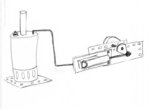
I wanted to build a steam engine I could bolt into the 'guts ' of a Meccano model. The boiler will be separate and connected to the engine by some soft copper tubing suitably lagged just like the real thing. Using all Meccano compatable parts will let me assemble the engine in different configurations to suit the need.
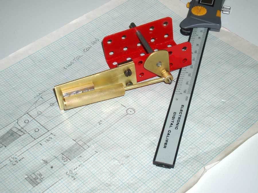
This is a 'back of an envelope' sketch of what I have in mind. (In fact it is the working drawings - altho I did some more on graph paper to get the scale right)
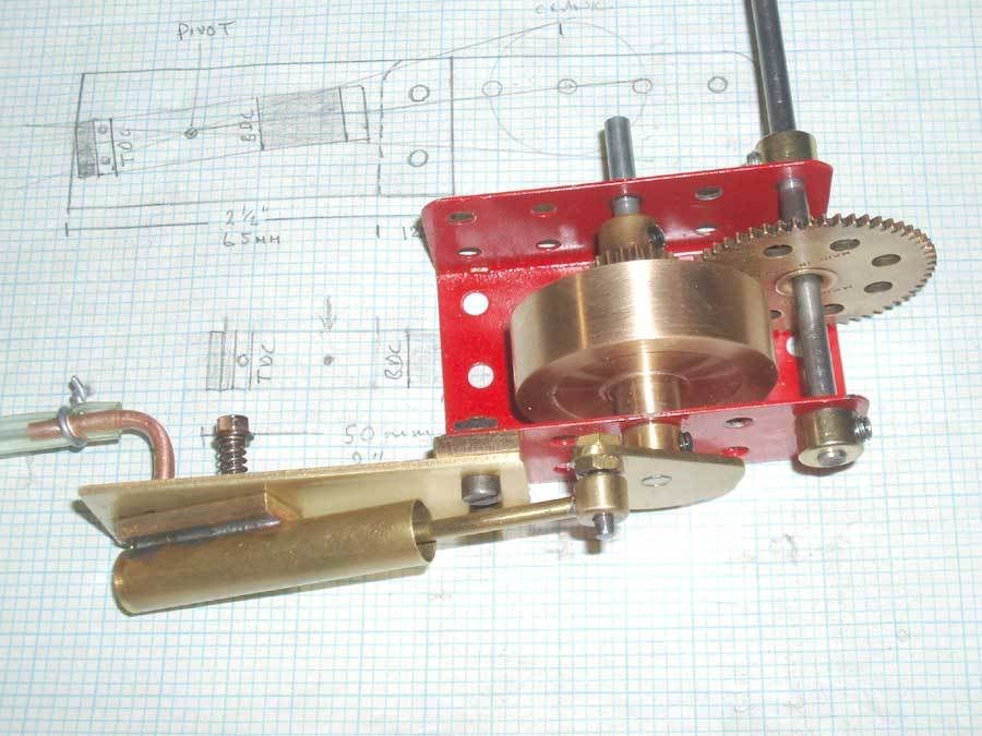
Ok so thats the idea. The whole thing is built on a Meccano U channel but could be any part of a model The crankshaft is a Meccano axle so I can fit gears and sprockets straight on it. I can even even bolt the cylinder on the other side of the U channel if needed. The flywheel can go outside the channel as shown or inside. All very flexible.
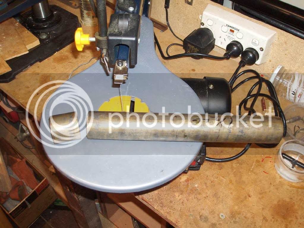
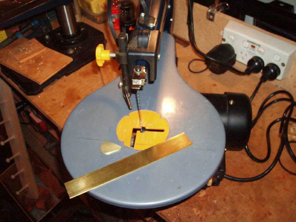
I started by cutting the brass plate bits on a $49.95 scroll saw fitted with a cut down junior hacksaw blade. Works great but gets thru a few blades -but they are cheap.
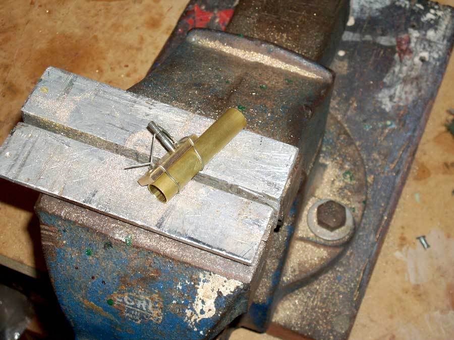
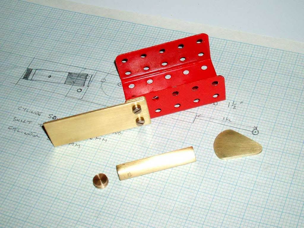
Also cut some tube for the cylinder and the crank for the crankshaft. Turned up a plug/cylinder head from bar stock.
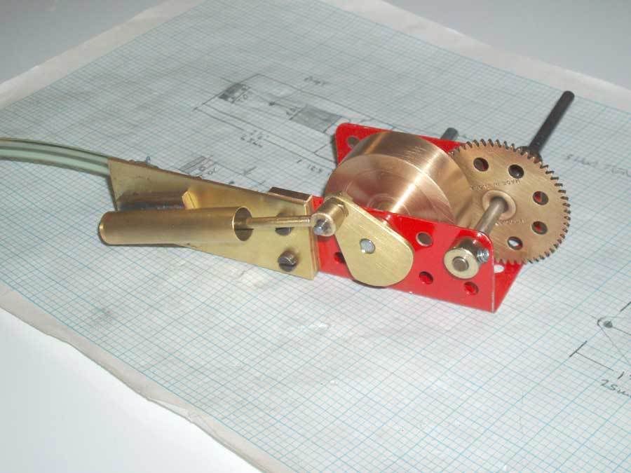
This is how it all looks so far.
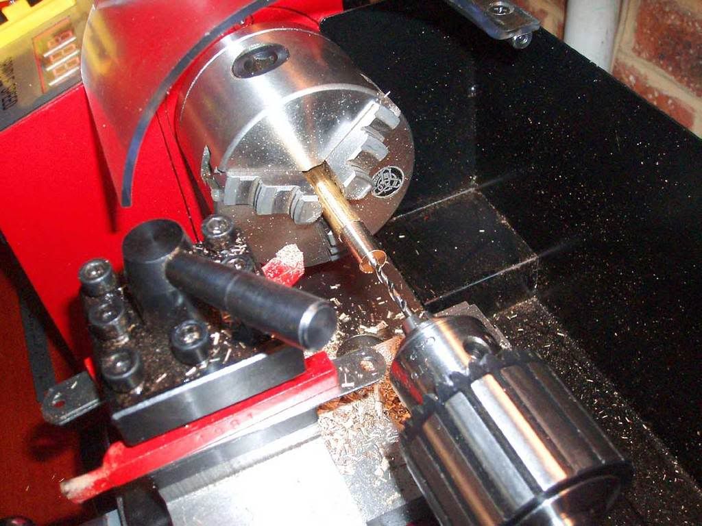
Started on the piston. Drilling the hole to fit the conrod.
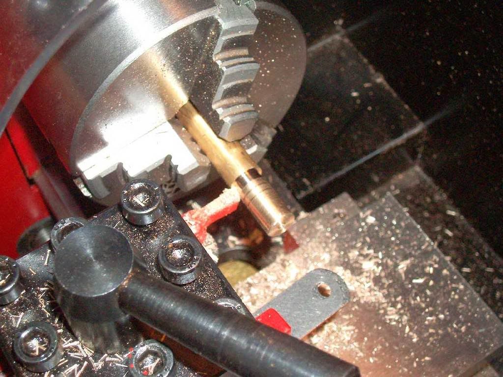
Parting off the piston. Made a couple of oil grooves to help with lubrication.
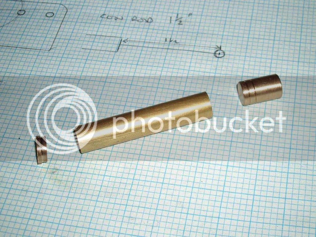
Here is the finished cylinder and piston.
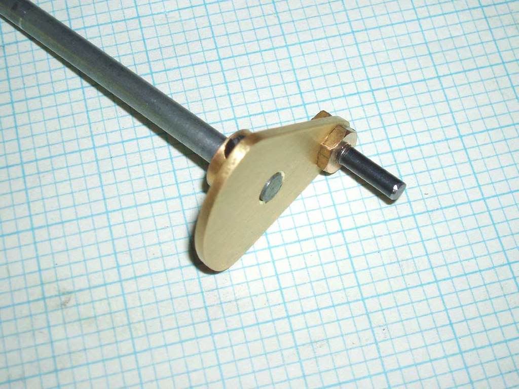
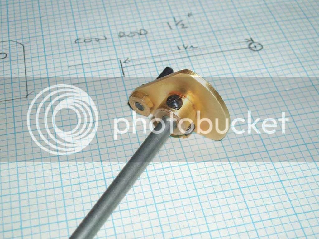
Turned up a boss for the crank to fit Meccano axle. Used a steel bolt for the crank pin. Soldered the boss to the crank and drilled through.
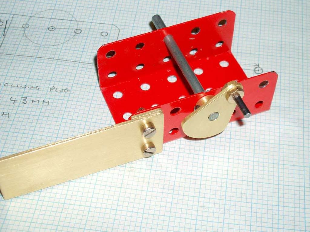
So here we are after a few hours work.
Now have to find some brass scrap for the flywheel and the valve block.
Off to the crap metal dealers again.
John
This is a 'back of an envelope' sketch of what I have in mind. (In fact it is the working drawings - altho I did some more on graph paper to get the scale right)
Ok so thats the idea. The whole thing is built on a Meccano U channel but could be any part of a model The crankshaft is a Meccano axle so I can fit gears and sprockets straight on it. I can even even bolt the cylinder on the other side of the U channel if needed. The flywheel can go outside the channel as shown or inside. All very flexible.
I started by cutting the brass plate bits on a $49.95 scroll saw fitted with a cut down junior hacksaw blade. Works great but gets thru a few blades -but they are cheap.
Also cut some tube for the cylinder and the crank for the crankshaft. Turned up a plug/cylinder head from bar stock.
This is how it all looks so far.
Started on the piston. Drilling the hole to fit the conrod.
Parting off the piston. Made a couple of oil grooves to help with lubrication.
Here is the finished cylinder and piston.
Turned up a boss for the crank to fit Meccano axle. Used a steel bolt for the crank pin. Soldered the boss to the crank and drilled through.
So here we are after a few hours work.
Now have to find some brass scrap for the flywheel and the valve block.
Off to the crap metal dealers again.
John